D. Temperature Setting Display Mode:
To adjust heat/cool setting:
1. Press <Up> or <Down> keys to adjust heat/cool setting temperature in normal
display mode.
2. Heat/ Cool setting temperature flashes.
3. In Heat mode, only heat setting temperature can be adjusted.
4. In Cool mode, only cool setting temperature can be adjusted.
5. In Auto mode, heat and cool setting temperature can be adjusted.
6. In Off mode, no setting temperature can be adjusted.
7. Press <Mode> key to exchange the heat and cool setting temperature in auto mode.
8. The operation will resume to normal display mode after no key is pressed for 10’s.
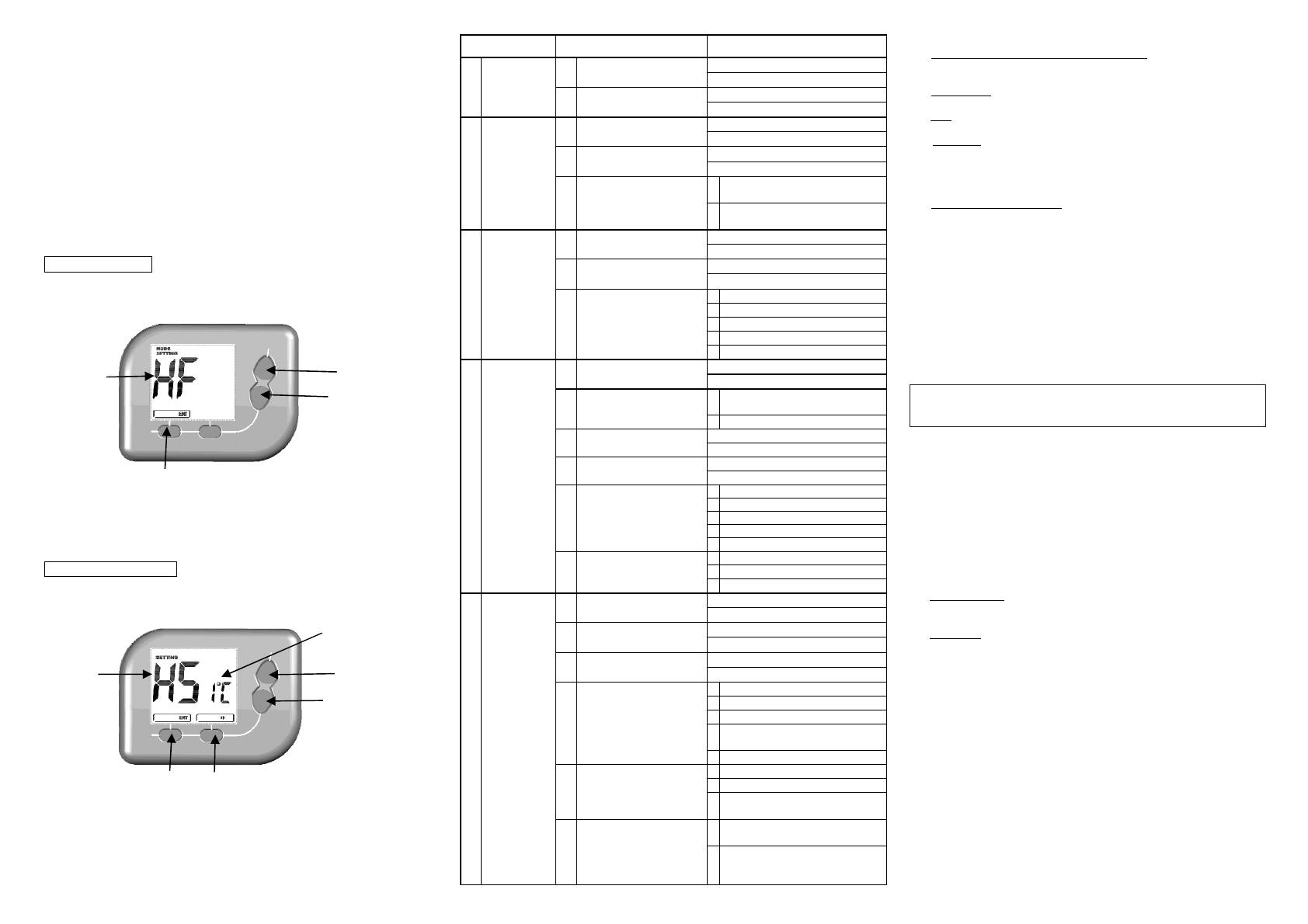
E. Internal Mode Setting Display:
To adjust the internal setting of Model PLVT1:
Mode Type Selection
1. Press and hold <Mode> and <Up> keys for 2’s.
2. LCD changes to the display of Mode type selection.
3. The letters represent Mode type.
4. Press <Up>/ <Down> to adjust Mode type.
5. Press <ENT> to select Mode type and return to normal display mode.
Function Setting Selection
1. Press and hold <Fan> and <Down> keys for 2’s.
2. LCD changes to the display of Function setting selection.
3. The left letters represent Function type; the right letters represent Setting.
4. Press <Up>/ <Down> to adjust Function type/ Setting.
5. Press <NEXT> to select Function type/ Setting.
6. Press <ENT> to return to normal display mode.
Table of the Internal Setting:
Mode type Function type Setting
HO
Heat only
(normal-open
or normal-close
valves)
HS
Span of Heater
1
C / 2
F
2
C/ 4
F
dU
Temperature Display Unit
C
F
HF
Heat with fan
HS
Span of Heater
1
C/ 2
F
2
C/ 4
F
dU
Temperature Display Unit
C
F
FC
Fan Control method
O
Gas or oil furnace – equipment
controls fan
E
Electric furnace – thermostat
controls fan
CL
Cool
dU
Temperature Display Unit
C
F
CS
Span of Cool
1
C/ 2
F
2
C/ 4
F
Cd
Compressor Minimum-
Delay
1
1 minute compressor off delay
2
2 minute compressor off delay
3
3 minute compressor off delay
4
4 minute compressor off delay
5
5 minute compressor off delay
HP
Heat pump
HS
Span of Heater
1
C/ 2
F
2
C/ 4
F
CO
Changeover Valve
C
O/B terminal energized in cooling
(default)
H
O/B terminal energized in heating
dU
Temperature Display Unit
C
F
CS
Span of Cool
1
C/ 2
F
2
C/ 4
F
Cd
Compressor/ Heater
Minimum-Off Delay
1
1 minute compressor off delay
2
2 minute compressor off delay
3
3 minute compressor off delay
4
4 minute compressor off delay
5
5 minute compressor off delay
SL
Mode Adjustment
1
Heat, Cool Off Selectable
2
Auto, off Selectable
3
Heat, Cool Off, Auto Selectable
HC
Electric/oil/gas
heat with cool
(Default
setting)
HS
Span of Heater
1
C/ 2
F (Default setting)
2
C/ 4
F
dU
Temperature Display Unit
C (Default setting)
F
CS
Span of Cool
1
C/ 2
F (Default setting)
2
C/ 4
F
Cd
Compressor Minimum-Off
Delay
1
1 minute compressor off delay
2
2 minute compressor off delay
3
3 minute compressor off delay
4
4 minute compressor off delay
(Default setting)
5
5 minute compressor off delay
SL
Mode Adjustment
1
Heat, Cool, Off Selectable
2
Auto, off Selectable
3
Heat, Cool Off, Auto Selectable
(Default setting)
FC
Fan Control Method
O
Gas or oil furnace – equipment
controls fan
E
Electric furnace – thermostat
controls fan
(Default setting)
Description of the mode types:
1. Heat only ( normal-open or normal -close valves)
Only Heat mode can be used for normal-open or normal -close valves, fan
cannot be selected.
2. Heat with fan
Only Heat mode can be used, fan can be selected.
3. Cool
Only Cool mode can be used, fan can be selected.
4. Heat pump
Heat/ Cool/ Auto mode can be selected with changeover valve.
(**While in auto mode. There is a Heat/Cool switching delay of 4 minutes to
switch a heating system to cooling system or vice versa. During the period
either Heater/Cooler or Fan will not turn on.)
5. Electric/oil/gas heat with cool
Heat/ Cool/ Auto mode can be selected. This is the default setting and common
used in factories.
F. Replaceable Batteries Instruction:
Batteries shall be installed with proper polarity and correct battery type.
Do not use old and new batteries simultaneously.
Batteries shall be removed if consumed or if product is to be left unused for
a long time. Use 1.5V/cell alkaline batteries 2 pieces.
G. Maintenance:
Caution: Switch off the electric source before maintenancing the
thermostat. We recommend that the maintenance should be
performed by trained personnel.
No heating/ cooling control:
- Check the thermistor sensor performance by measuring the corresponding
variable resistance under different temperatures. If it is in good condition and the
LCD value will change accordingly, then trace the control circuit or the LCD
connection, otherwise replace it.
- If the control circuit has a problem, replace the PCB if necessary.
H.
Specification:
1. Temperature measurement: 0°C~40°C / 32° F ~ 99°F
2. Accuracy: ±0.5°C/ 1°F
3. Temperature Controllable range:
Heat/Cool mode:
Heat/Cool setting: 5°C~35°C / 40° F ~ 95°F
Auto mode:
Heat setting: 5°C~30°C / 40° F ~ 85°F
Cool setting: 10°C~35°C / 50° F ~ 95°F
4. Resolution: 0.5°C /1°F
5. Power Supply: 24V~ +/-10% or 2 x AAA alkaline
batteries
6. Rating: 24V~ 50/ 60Hz 1A max
7. Terminals: 2mm
2
cable
8. Operating temperature: 0 – 50 °C / 32 – 122 °F
9. Storage temperature:
-5 – 50 °C/ 23 – 122 °F
10. Sensing Element: NTC thermistor
<Up> key
<
> key
Mode Type
<Up> key
<
> key
<
> key
Function
type
<NEXT> key
Setting


