Page is loading ...

WARNING! TO PREVENT SERIOUS INJURY
AND PROPERTY DAMAGE.
1. Wear ANSI-approved safety goggles and heavy-duty
work gloves during use. If not properly used, the tool’s
scissor-like action may cause pinch injury.
2. Keep away from children. Small pieces can be choking
hazard. Dispose of rivets and all small pieces properly.
3. Inspect before every use; do not use if damaged.
4. Use as intended only.
WARNING: The warnings, cautions, and instructions discussed
in this instruction manual cannot cover all possible conditions and
situations that may occur. It must be understood by the operator
that common sense and caution are factors which cannot be built
into this product, but must be supplied by the operator.
WARNING: This product contains di (2-ethylhexyl) phthalate
(DEHP), a chemical known to the State of California to
cause cancer and birth defects or other reproductive harm.
(California Health & Safety Code § 25249.5, et seq.)
NOTE: Rivets, rivet nuts and anchor rivets are not supplied with
this kit. They must be purchased separately.
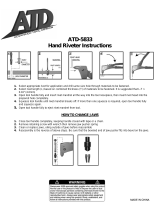
To install Blind Rivets (3/16″, 5/32″, 1/8″ or 3/32″):
1. Drill proper sized hole for rivet you are using.
2. Select and install correct Nosepiece (11,12,13
or 14). Nosepieces have standard right
hand thread for installing/removing.
3. Place rivet in the hole and place
Nosepiece over stem of rivet.
4. Squeeze handle once or twice until stem snaps off rivet.
5. Open handle and turn tool upside
down to allow stem to fall out.
To Change the Case and Install Rivet Nuts and Anchor Rivets.
To Change the Case:
1. Remove any installed Nosepiece by
turning it counterclockwise.
2. Hold Pivot Pin (8) against handle to prevent
it from turning. Loosen Pivot Pin Nut (9) by
turning it clockwise with Wrench (4).
3. Squeeze Lever (2) down and pull it back
along Frame (1). This will disengage
Lever (2) from Axis Pin (19).
4. Remove Jaw Case (15) from tool.
5. Insert Nut & Anchor Case (20).
6. Push Handle back in place, being sure
that Case Pins fit into Handle slots.
7. Push Pivot Pin (8) back in place and
retighten it with Wrench (4).
To Install Rivet Nuts (1/4-20, 110-24, 8-32 or 6-32):
1. Drill proper sized hole for Rivet Nut to be used.
2. Thread proper Nut Mandrel (21, 22, 23
or 24) onto Nut & Anchor Case (20).
3. Thread Rivet Nut onto Mandrel.
4. Insert Rivet Nut into hole and squeeze handle.
This will expand Rivet Nut in hole.
5. Unscrew tool from Rivet Nut.
To Install Anchor Rivets (6-32x1-1/4″ or 6-32x2-3/8″):
1. Drill proper sized hole for Anchor Rivet to be used.
2. Thread proper Anchor Mandrel (25 or 26)
onto Nut & Anchor Case (20).
3. Thread Anchor Rivet onto Mandrel.
4. Insert Anchor Rivet into hole and squeeze handle.
This will expand Anchor Rivet in hole.
5. Unscrew tool from Anchor Rivet.
Part # Description QTY.
1 Frame Assembly 1
2 Lever Assembly 1
3 Grip 2
4 Wrench 1
5 Lock 1
6 Return Spring 1
7 Spring Pin 1
8 Pivot Pin 1
9 Pivot Pin Nut 1
10 “S” Clip 2
11 Nose Piece 3/16″ Rivet 1
12 Nose Piece 5/32″ Rivet 1
13 Nose Piece 1/8″ Rivet 1
14 Nose Piece 3/32″ Rivet 1
15 Jaw Case 1
16 Jaws 1
17 Jaw Pusher 1
18 Jaw Spring 1
19 Axis Pin 1
20 Nut & Anchor Case 1
21 Nut Mandrel Set 1/4 - 20 1
22 Nut Mandrel Set 10 - 24 1
23 Nut Mandrel Set 8 - 32 1
24 Nut Mandrel Set 6 - 32 1
25 Anchor Mandrel 6 - 32 x 1-¼” 1
26 Anchor Mandrel 6 - 32 x 2-3/8″ 1
Includes noses-pieces for 3/32″, 1/8″, 5/32″ and 3/16″ blind
rivets and blind rivet nosepieces
Maximum rivet capacity: 3/16″
Threaded nut sizes: 6-32, 8-32, 10-24, 1/4″-20.
Anchor mandrel lengths: 1-1/4″ and 2-3/8″
NOTE: Some parts are listed and shown for illustration purposes only and are not available individually as replacement parts.
#traP noitpircse .D YTQ #traP noitpircse .D YTQ
1 ylbmessAemar 41F t1 eviR"23/3eceiPeso 1N
2 ylbmessAreve 51L 1 esaCwa 1J
3 pir 62G 1 swa 1J
4 hcner 71W 1 rehsuPwa 1J
5 kco 81L 1 gnirpSwa 1J
6 gnirpSnrute 91R 1 niPsix 1A
7 niPgnirp 01S e2 saCrohcnA&tu 1N
8 niPtovi 11P 02 2-4/1teSlerdnaMtu 1N
9 tuNniPtovi 21P 42 2-01teSlerdnaMtu 1N
01 pilC"S 32" 22 3-8teSlerdnaMtu 1N
1 t1 eviR"61/3eceiPeso 41N 22 3-6teSlerdnaMtu 1N
2 t1 eviR"23/5eceiPe
so 51N "2 ¼-1x23-6lerdnaMrohcn 1A
3 t1 eviR"8/1eceiPeso 61N "2 8/3-2x23-6lerdnaMrohcn 1A
Assembly Diagram
Parts List
20
21
22
23
24
25
26
18
17
16
12
10
8
15
14
11
19
13
10
9
6
7
2
4
3
3
1
5
/