
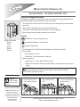
MODELS INCLUDED
•RU-150
•RU-225
•RU-300
•RU-600
•RU-1000
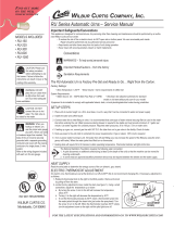
CAUTION: Please use the setup procedures in this manual before attempting to use brewer.
Failure to follow the instructions can result in injury or the voiding of the warranty.
Seesetupproceduresonpage2.
Technical Support: 1-800-995-0417 M-F 5:30am-4:00pm PT
Email: [email protected]
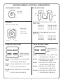
TheRUAutomaticUrnisFactoryPre-SetandReadytoGo…RightfromtheCarton.
Factory Settings:
•BrewTemperature=200°F
•BrewVolume=Settorequirementsofcoffeeliner
SystemRequirements
•WaterSource:20–100psi(MinFlowRateof1gpm)
•Electrical:Seeattachedschematicforstandardmodelorvisitwww.wilburcurtis.comforyour
model.
2. Rotate spray head over
bed of coffee inside
lter.
3. Press the BREW but-
ton on control panel to
begin brewing.
Brewing Instructions
WARNING HOT
LIQUID, Scalding
may occur. Avoid
splashing.
This appliance is designed for commercial use. Any servicing other than cleaning and maintenance
shouldbeperformedbyanauthorizedWilburCurtisservicecenter.
• Toreducetheriskofreorelectricshock,donotopensideorbottompanel.Nouserserviceable
parts inside.
• Repairshouldbeperformedonlybyauthorizedservicepersonnel.
• Keephandsandotheritemsawayfromhotpartsofunitduringoperation.
• Nevercleanwithscouringpowders,bleachorharshchemicals.
Important Safeguards/Symbols
Symbols
WARNINGS–Tohelpavoidpersonalinjury
ImportantNotes/Cautions–fromthefactory
SanitationRequirements
1. Place lter in basket.
Pour coffee into lter.
Place basket into liner.
Service Manual – RU Series Automatic Urns
Wilbur Curtis Company, inC.
ISO 9001:2008 REGISTERED
WILBUR CURTIS CO., INC.
6913 West Acco Street
Montebello, CA 90640-5403
For the latest information go to
www.wilburcurtis.com
Tel: 800-421-6150
Fax: 323-837-2410

2
1. Attach adjustable legs, threading them into
the holes beneath the four corners of the urn.
2. Place unit at counter height, on a rm, level
base, near water and power supply connec-
tions.
3. Install the water and coffee faucets.
4. Connect water line to inlet tting on valve. All
Curtis Automatic Urns are equipped with a
¼” male are tting which must be connected
to the water supply with a ¼” copper tubing
and a ¼” are nut. Water pressure enter-
ing brewer is required to be stable and must
provide minimum of 1 gallon per minute. Use
water regulator for constant pressure. Re-
quired water pressures, 20 to 100 psi.
CAUTION: DO NOT connect this urn to
hot water. The inlet valve is not rated for
hot water.
5. Turn on water valve.
6. Hook-up electrical power to the unit (refer to
schematic for power requirements). If gas or
steam, 120V circuit is required.
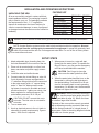
UNPACKING THE URN
All urns are carefully packed in cartons with lami-
nated cardboard inserts. The packaging is speci-
cally to tted to your urn. The packaging exceeds
the requirements of the I. C. C. regulations.
Inspect all containers at the time of delivery for
visual or concealed damage. In case of punctured
or damaged cartons the carrier must be notied im-
mediately.
ITEM QTYTWINQTYSINGLE
WIREBASKET
LIDWITHKNOB
FAUCET,HOTWATER
FAUCET, COFFEE
LEGS,ADJUSTABLE
FILTERS,PAPER
SERVICEMANUAL
1
1
1
1
4
25
1
2
2
1
2
4
40
1
PACKING LIST
INSTALLATION AND OPERATING INSTRUCTIONS
7. When power is turned on, water will start
owing into the water jacket. To expedite the
lling of the urn, you may use the emergency
rell valve located behind the machine.
CAUTION Don’t forget to close the
valve once the water jacket has lled.
8. When the water jacket has lled, turn on the
thermostat by turning the dial clockwise to
the desired setting. It will take 50 to 60 min-
utes for the heating tank to reach operating
temperature. On electric urns, the thermostat
indicator will light at this time.
WARNING When you hookup an electric
urn, use the proper wire gauge, plus 25%
(see table on page 12). Never use fuses
or breakers larger than needed.
The body of the urn must be securely grounded
with a separate grounding conductor and never
with the neutral conductor of a single phase, 3
wire system. Refer to the wiring diagram included
with each urn for wire gauge.
WARNING:DONOTplacethisurncloserthansix[6]inchesfromwall.Urnmusthaveadequatecross-ventilation.
SETUP STEPS
NOTE: A water ltration system must be used to help maintain trouble-free operation. Air must
be purged from the cartridge prior to connection to equipment. In areas with extremely hard
water, we recommend the use of a Curtis approved water lter. For our full line of lters, please
log on to www.wilburcurtis.com.

3
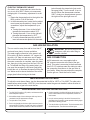
CARE AND MAINTENANCE OF URN
PREVENTIVE MAINTENANCE
I. Remove the spray head from the urn and clean
it once a week. More often in heavy lime
areas.
WARNING Switch off the power to the unit
at the circuit breaker. Turn off the water line
running to the urn.
2. Clean the faucet seat cups twice a week and
replace when cracked or leaking.
3. Periodic temperature checks and thermostat
adjustments should be made by authorized
personnel.
CLEANING
To ensure the highest quality coffee, the urn must
be cleaned daily after the last batch of coffee is
used.
Regular cleaning and preventive maintenance is
essential in keeping your coffee urn looking and
working like new.
CAUTION Do not use cleaning products
containing chemicals that will damage
stainless steel, ammonia and bleaches
containing chlorine. Never use abrasives that will
scratch the outside surface of the urn.
DAILY CLEANING INSTRUCTIONS
WARNING These steps involve working
with very hot water.
I. After all the brewed coffee has been drawn from
the urn, run a brew cycle of fresh water. Spray
the hot water into the liner, then thoroughly
brush it out with a long handled brush.
2. Drain the water off then repeat step one. Run
another brew cycle. Brush out the liner and
drain. Wipe down the liner with a clean towel.
3. If urn is not going to be used immediately, pour
a gallon or two of fresh water into the liner.
Remember to drain off this water before making
another brew.
4. Wash the wire brew baskets with urn cleaner
and rinse thoroughly.
TWICE A WEEK
Coffee urns must have a special coffee liner
scouring twice a week.
1. Be sure water jacket is full of water and tem-
perature is at brewing temperature.
2. Fill the liner with several gallons of water and
add at least 1½ ounces of coffee urn clean-
ing compound. Allow this solution to remain in
the liner approximately 30 minutes. During this
time, the thermostat should be set to BOIL.
WARNING Very hot water.
3. Scrub the inside of the liner and cover with a
long handled brush.
4. Drain the all the urn cleaning solution and rinse
by running several brew cycles with the spray
head centered over the liner, draining the rinse
water between sprays.
5. Thoroughly clean the faucets.
WARNING Never remove the faucet
when the liner has water or coffee in it.
Switch off the power to the unit at the circuit
breaker. Turn off the water line running to the
urn.
Use a long thin gauge glass brush to clean the
coffee gauge glass. Use the same brush to
clean the tting at the bottom of the liner and
the pipe connecting to the coffee faucet.
6. Leave a gallon or two of fresh water in the
liner. Drain just before brewing coffee.
7. After the unit is clean, return the water and
power to the unit.

4
1
2
2A
3
3A
3B
17
4
4A
4B
4C
5
7
6
8
8
9
9A
10
11
13
19
12
14
15
18
20
68
16
35
37
37A
41
41A
41B 40
39
34
33
49
48
25
28
24
21
21A
21B
21C
23
29
51
12
30 22
26
15
11
50
47
47A
47B
47C
52
43
46
42
44
86
45
42
31
31A
31B
27
83
84
67
66 65
69
60
61
62
63
63A
63B
63C
64
64A
64B
64C
74
91
56
35
54
53
*82 NOT INCLUDED WITH GAUGE GLASS ASSEMBLY.
85
35
34
78
78A
78B
78C
77
76
82*
61
79
79A
79B
79C
81
72
70
87
71
74
75
73
80
80A
80B
80C
80D
58
32
32A
36
38
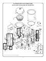
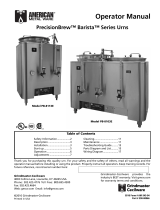
ILLUSTRATED PARTS LIST AUTOMATIC URNS,
RU-150, RU-225, RU-300, RU-600, RU-1000 ELECTRIC

5
1 WC-3205 KNOB URN LID 1/4-20 FEMALE THREAD ALL RU URNS
2 WC-5601 LID, LINER ASSEMBLY RU-150, RU-300
2A WC-5603 LID, LINER ASSEMBLY RU-225, RU-600, RU-1000
3 WC-3302 BREW BASKET WIRE W/FLAPS RU-150, RU-300
3A WC-3303 BREW BASKET WIRE W/FLAPS RU-225, RU-600
3B WC-3304 BREW BASKET WIRE W/FLAPS RU-1000
4 WC-5700 LINER, 3 GAL RU-150
4A WC-5706 LINER, 6 GAL RU-225, RU-600
4B WC-5704 LINER, 3 GAL RU-300
4C WC-5708 LINER, 10 GAL RU-1000
5 WC-4303 O’ RING, LINER RU-150, RU-300
5A WC-43076 O’ RING, LINER RU-225, RU-600, RU-1000
6 WC-1200 CORD, 14/3 SJTO 6’ BLACK WITH PLUG ALL GAS, STEAM & 3Ø RU URNS
7 WC-1408 GRIP, CORD 7/8” OD ALL GAS, STEAM & 3Ø RU URNS
8 WC-806 VALVE, 1/4” GATE PLATED ALL RU URNS
9 WC-53104 TUBE ASSY, 1/4x14.50 ER W/NUTS RU-150, RU-300
9A WC-53105 TUBE ASSY, 1/4x17.00 ER W/NUTS RU-225, RU-600
9B WC-53109 TUBE ASSY, 1/4” ER W/NUTS RU-1000
10 WC-2705 TEE, 1/4 X 1/4 FLARE X 3/8 NPT PLATED ALL RU URNS
11 WC-3217 KNOB, THERMOSTAT ALL RU URNS
12 WC-801 VALVE, INLET BRASS .50 GPM 120V 10W ALL RU URNS
13 WC-3700 KIT, INLET VALVE REPAIR ALL RU URNS
14 WC-813 FLOW WASHER, .5 GPM .5” S45 ALL RU URNS
15 WC-3220 BEZEL, THERMOSTAT ELECTRIC URNS ALL RU URNS
16 WC-301 TERMINAL STRIP, 4-S ALL RU URNS (BEFORE 1/29/13)
17 WC-3305 FLAPS WIRE BASKET (2 REQUIRED) RU-150 & RU-300
18 WC-37166 KIT, AIR PUMP RU’S ALL RU URNS
19 WC-5843 BRACKET, AERATOR PUMP ALL RU URNS
20 WC-3600 T-CONNECTOR 3/16 POLYPROPYLENE RU-150 & RU-225
21 WC-39570 LABEL, INSTRUCTION PANEL RU-150 & RU-300 (AFTER 1/29/13)
21A WC-39571 LABEL, INSTRUCTION PANEL RU-225 & RU-600 (AFTER 1/29/13)
21B WC-39574 LABEL, INSTRUCTION PANEL RU-1000 (AFTER 1/29/13)
22 WC-2405 ELBOW, 1/2 FLARE x 1/2 NPT ALL RU URNS
23 WC-2609 SWIVEL, 1/2” TUBE X 1/2 NPT ALL RU URNS
24 WC-2504 ELBOW, 1/2 NPT X 1/2 NPT ALL RU URNS
25 WC-1037 PUMP, WATER W/FITTINGS 120VAC ALL RU URNS
26 WC-3702 KIT, WATER PUMP SEAL RU’S ALL RU URNS
27 WC-37165 KIT, THERMOSTAT WC-500A/501A ALL RU URNS
28 WC-2605 CONNECTOR, 3/8” FLARE x 3/8” ALL RU URNS
29 WC-2608 SWIVEL, 3/8 TUBE x 3/8 NPT ALL RU URNS
30 WC-2403 ELBOW, 3/8 FLARE x 3/8 NPT PLATED GEN USE ALL RU URNS
31 WC-5808 DOOR, CONTROL BOX LOUVER RU-225, RU-600
31A WC-5807 DOOR, CONTROL BOX LOUVER ACB RU-150, RU-300
31B WC-5809 DOOR, CONTROL BOX LOUVER RU-1000
32 WC-5322 TUBE ASSY, 1/4 X 20.00 W/NUTS RU-225, RU-600
32A WC-5321 TUBE ASSY, 1/4x17.00 WI W/NUTS RU-150, RU-300
33 WC-2929 FITTING, 1/2 NIPPLE/NUT BRASS ALL RU URNS
34 WC-300 POWER BLOCK 3-STA 175A 600V ALL RU URNS
35 WC-5307 TUBE, 3/16 ID x 3/32W SILICONE ALL RU URNS
36 WC-522 THERMOSTAT, HIGH LIMIT HEATER ALL RU URNS
37 WC-402* RELAY HOLDING 120V COIL 20A ALL RU URNS (BEFORE 1/29/13)
37A WC-403* RELAY HOLDING 120V 3 POLE RU-1000 (BEFORE 1/29/13)
DESCRIPTIONINDEX № PART № EQUIPMENT USED ON
* ITEMS 37 AND 37A, AFTER 1/29/13 SEE ITEMS 45, 45A, 45B

6
38 WC-102 SWITCH, TOGGLE NON-LIT SPST ALL RU URNS
39 WC-5502-01 KIT, PROBE, WTR LVL W/FTNG, O’RING, NUT ALL RU URNS
40 WC-405R-101 TIMER, AGITATION 90-260 VAC 30 SEC ALL RU URNS
40A WC-405R TIMER, AGITATION 120V 50/60Hz WIR/BRKT ALL RU URNS
41 WC-304 TERMINAL STRIP 14-S RU-225, RU-600, RU-1000
41A WC-303 TERMINAL STRIP 12-S RU-150, RU-300
41B WC-302 TERMINAL STRIP 6-S RU-1000
42 WC-3737 KIT, BREW SWITCH 120V RU’S ALL RU URNS
43 WC-5802 BRACKET, WATER LEVEL CONTROL ALL RU URNS
44 WC-608-101K KIT,LIQUID LEVEL CONTROL BOARD ALL RU URNS
45 WC-603-101K-RU KIT, RETROFIT TIMER,120V RU-300 W/½BB ALL RU URNS
45A WC-622-101K-RU KIT, BREW TIMER, 220V RU-300 NO ½BB RU-300 220V
45B WC-603-102K-RU KIT, BREW TIMER, 220V RU-1000 ⅓ BB RU-1000 220V
46 WC-101 SWITCH, ON/OFF NON-LIT MOMENT SPST ALL RU URNS
47 WC-3903 LABEL, INSTRUCTION PANEL RU-600
47A WC-3900 LABEL, INSTRUCTION PANEL RU-150
47B WC-3901 LABEL, INSTRUCTION PANEL RU-225
47C WC-3902 LABEL, INSTRUCTION PANEL RU-300
47D WC-3904 LABEL, INSTRUCTION PANEL RU-1000
48 WC-3528 LEG, 4” ADJUSTABLE 3/8-16 THREAD ALL RU URNS
49 WC-100 SWITCH, RESET-STOP NC NL MOMENTARY ALL RU URNS
50 WC-1501 FUSE HOLDER W/5A FUSE ALL RU URNS
51 WC-1500 FUSE, 5 AMP ALL RU URNS
52 WC-511 THERMOMETER, DIAL ALL RU URNS
53 WC-5313 TUBE ASSY, 1/2” SPRAY ARM W/NUTS RU-300, RU-150
53A WC-5314 TUBING 1/2” SPRAY ARM W/NUTS RU-225, RU-600
53B WC-5315 TUBING 1/2” SPRAY ARM W/NUTS RU-1000
54 REFER TO VALVE CORE & SPRAY ARM ON PAGE 8
56 WC-5800 RING, STEAM ALL RU URNS
58 WC-2007 BRACKET, GAUGE GLASS ALL RU URNS
60 WC-2003 CAP, PLUG VENTED 44 ALL RU URNS
61 WC-2002 CAP, SHIELD W/CLEAN OUT HOLE ALL RU URNS
62 WC-2030 GLASS, GAUGE 13”
63 WC-2108 GAUGE GLASS ASSEMBLY 13” RU-225, RU-600
63A WC-2104 GAUGE GLASS ASSEMBLY 10” RU-150
63B WC-2105 GAUGE GLASS ASSEMBLY 11” RU-300
63C WC-2113 GAUGE GLASS ASSEMBLY 19” RU-1000
64 WC-2017 SHIELD, GAUGE GLASS 13” RU-225, RU-600
64A WC-2104 SHIELD, GAUGE GLASS 10” RU-150
64B WC-2014 SHIELD, GAUGE GLASS 11” RU-300
64C WC-2022 SHIELD, GAUGE GLASS 19” RU-1000
65 WC-1900 VALVE, GAUGE SHIELD SHUT OFF ALL RU URNS
66 WC-1800L FAUCET, “S” SERIES LOCKING ALL RU URNS
70 WC-1805 SEAT CUP, S’ FAUCET SILICONE ALL RU URNS
71 WC-3705 KIT, S’ FAUCET REPAIR ALL RU URNS
72 WC-1906 C’ RING .917 X .760 X .090 ALL RU URNS
73 WC-1903 NUT, UNION SHANK ALL RU URNS
76 WC-2004 SHIELD BASE, GAUGE GLASS ALL RU URNS
77 WC-2006 WASHER, .188 ID X .188 THICK BOTTOM ALL RU URNS
78 WC-2031 GLASS, GAUGE ⅝” x 14” RU-225, RU-600
78A WC-2028 GLASS, GAUGE ⅝” X 11” RU-150
78B WC-2029 GLASS, GAUGE ⅝” X 12” RU-300
78C WC-2037 GLASS, GAUGE ⅝” X 20” RU-1000
DESCRIPTIONINDEX № PART № EQUIPMENT USED ON
BEFORE
1/29/13

7
PARTS LIST EXPORT 220V CONTROLS*
WC-3738
WC-410
WC-417
WC-622-101K-RU
WC-633
WC-858
WC-1009
KIT, BREW SWITCH 220V RU RPL
COIL FOR INLET VALVE (220V) S45
RELAY, HOLDING 220V 2P 10A RU (AFTER 1/29/13)
KIT, RETROFIT TIMER, BREW SELECTOR 220V
TIMER, CUBE W/BRACKET 240V 25 SEC
VALVE, INLET BRASS .50 GPM 220V 10W
PUMP, AGITATION (220V)
1
2
3
4
5
6
7
PARTS LIST DOUBLE SERVICE URNS
WC-5701
WC-5703
WC-5705
WC-5707
WC-5709
WC-5458
LINER, 3 GAL
LINER, 6 GAL
LINER, 3 GAL
LINER, 6 GAL
LINER, 10 GAL
STEAM RING PLATE
1
2
3
4
5
6
PARTS LIST 220V, 3 PHASE URNS (3W +G or 4W +G)*
WC-431
WC-703
WC-710
WC-1200
WC-1408
WC-37165
WC-502
CONTACTOR, 120V 60A 3P DP
TRANSFORMER, .5KVA 240-120V
TRANSFORMER, 240/480 120V,500VA
CORD, 14/3 SJTO 6’ BLK (3PH 3W+G W/120V BOX)
CORD GRIP
KIT, THERMOSTAT WC-500A/501A
THERMOSTAT, CAPILLARY LWC OFF DPST
1
2
3
4
5
6
7
79 WC-2019 SHIELD, GAUGE GLASS 14” RU-225, RU-600
79A WC-2014 SHIELD, GAUGE GLASS 11” RU-150
79B WC-2016 SHIELD, GAUGE GLASS 12” RU-300
79C WC-2023 SHIELD, GAUGE GLASS 20” RU-1000
80 WC-2109 GAUGE GLASS ASSEMBLY 14” RU-600, RU-225
80A WC-2105 GAUGE GLASS ASSEMBLY 11” RU-150
80B WC-2107 GAUGE GLASS ASSEMBLY 12” SHORT WIN RU-300
80C WC-2114 GAUGE GLASS ASSEMBLY 20” RU-1000
81 WC-2005 SHIELD CAP, WASHER, 1/8” ALL RU URNS
82 WC-2000 FITTING, AGITATION PLATED ALL RU URNS
83 WC-4205 NUT, 1/4 LOCK NPS BRASS ALL RU URNS
84 WC-2913 SPOUT OVERFLOW ALL RU URNS
85 WC-5810 COVER, ELECTRIC BOX RU-600, RU-1000
86 WC-4305 WASHER 5/8” TEFLON ALL RU URNS
87 WC-3402 SPRING, RETURN S SERIES FAUCET ALL RU URNS
88 — REFER TO HEATING ELEMENT CHART ON PAGE 9
RU-150DS
RU-225DS
RU-300DS
RU-600DS
RU-1000DS
ALL DS RUs
ALL 220V RU
ALL 220V RU
ALL 220V RU
RU-300 NO ½BB
ALL 220V RU
ALL 220V RU
ALL 220V RU
ALL 220V 3-PH RU
ALL 220V 3-PH RU
ALL 220V 3-PH RU
ALL 220V 3-PH RU
ALL 220V 3-PH RU
ALL 220V 3-PH RU
ALL 220V 3-PH RU
DESCRIPTIONINDEX № PART №
EQUIPMENT
USED ON
*REFERENCE THE ELECTRICAL DIAGRAM FOR YOUR SPECIFIC UNIT.

8
1
2
3
4
5
6
7
8
9
10
11
12
13
14
15
16*
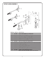
WC-2909
WC-2908
WC-4800
WC-3103
WC-4307
WC-2916
WC-4202
WC-2914
WC-3753
WC-4310
WC-4215P
WC-3109
WC-2904
WC-4320
WC-2907
WC-3200
SPRAY ARM ASSEMBLY, RU-225/600/1000
SPRAY ARM ASSEMBLY, RU-300, RU-150
SCREW, 8-32 x 1/8” SET S.S.
CAP, CLEAN OUT VALVE CORE PLATED
RING, PACKING TEFLON 2-REQUIRED
NEEDLE, BY-PASS PLATED (SPRAY ARM)
NUT, 3/8” - 24 JAM, PLATED
SPOUT, BY PASS PLATED (SPRAY ARM)
KIT, VALVE CORE REPLACEMENT
WASHER, 7/8” INTERNAL TOOTH LOCK 410 STAINLESS STEEL
NUT, 7/8” JAM BRASS
VALVE CORE, PLATED
SPRAY HEAD HOLDER PLATED
“O” RING, ½”ID BUNA #.016
SPRAY HEAD, ASSY (SC)RU-150/225/300/600/1000
HANDLE, SPRAY ARM BLACK PLASTIC
* Use only with valve cores that do not have Teon restrictors.
INDEX № PART № DESCRIPTION
SPRAY ARM ASSEMBLY

9
RU-150 & WB-14 1 PHASE
RU-300, 600 & 1000 3 PHASE
RU-225 1Ø
RU-150 & 225 3 PHASE
RU-300, 600 & 1000 1 PHASE
WC-913-01
220V, 5 KW
THESE ELEMENTS
ARE INTERCHANGE-
ABLE
220V, 1PH, 3 WIRE + GND
-02-01
RU-300 7.5 KW, 208/220V, 3PH, 3 OR 4 WIRE
+ GND.
3 - WC-908 220V @ 2.5 KW EA.
RU-600 10.5 KW, 208/220V, 3PH, 3 OR 4 WIRE
+ GND.
3 - WC-911 220V @ 3.5 KW EA.
RU-1000 10.5 KW, 208/220V, 3PH, 3 OR 4 WIRE
+ GND.
3 - WC-911 220V @ 3.5 KW EA.
RU-150-20 5.25 KW, 208/220V, 3PH, 3 OR 4
WIRE + GND.
WC-907-01 220V @ 1.75 KW
WC-907-02 220V @ 1.75 KW
WC-907 -03 220V @ 1.75 KW
RU-225-20 7.5 KW, 208/220V, 3PH, 3 OR 4
WIRE + GND.
WC-908-01 220V @ 2.5 KW
WC-908-02 220V @ 2.5 KW
WC-908-03 220V @ 2.5 KW
WC-911 -01
220V, 3.5KW
WC-911-02
220V, 3.5 KW
RU-300 6 KW, 208/220V, 1PH, 3 WIRE + GND
2 - WC-910 220V @ 3 KW EACH
RU-300 8 KW, 208/220V, 1PH, 3 WIRE + GND
2 - WC-912 220V @ 4 KW EA.
RU-600 10 KW, 220V, 1PH, 3 WIRE + GND
2 - WC-913 220V @ 5 KW EACH
RU-600 8 KW, 220V, 1PH, 3 WIRE + GND
2 - WC-912 220V @ 4 KW EACH
RU-1000 10 KW, 220V, 1PH, 3 WIRE + GND
2 - WC-913 220V @ 5 KW EACH
THESE ELEMENTS
ARE INTERCHANGE-
ABLE
HEATING ELEMENTS, LOCATION & CONFIGURATION
-01 -02 -03
(LEFT)
(CENTER)
(RIGHT)
(SPIRAL)
(CENTER)(EXTERIOR)

10
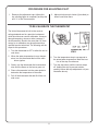
ELECTRIC THERMOSTAT ADJUST
On electric urns, thermostats are set at the fac-
tory to cut off at 200ºF. We do not recommend
changing this. If necessary, adjustment is as fol-
lows:
1. Rotate the thermostat knob to the right to the
BOIL position. Pull off the knob.
2. In the thermostat stem, locate the tiny adjust-
ment screw (see illustration). Using a small
screwdriver, adjust the temperature up or
down:
a. Turning the screw ¼ turn to the left will
increase the temperature about 20°F.
b. Turning the screw ¼ turn to the right will
decrease the temperature by 20°F.
c. To set the thermostat precisely at 200°F,
insert a thermometer probe into the water
The urn must be away from wall no less than 6”
and must have plenty of cross ventilation.
The water supply connection is the same in all
RU models. All that is needed is 1/4” copper tub-
ing with a 1/4” are nut and some sort of water
lter in the line before water enters the unit. Once
the water connection is complete, open the water
line, then plug in the power cord into an 115V out-
let. To facilitate the lling of the water jacket, you
can open the emergency rell faucet (red knob)
behind the unit, to increase the speed of lling the
urn. Water must be above the base of the center
gauge glass before turning on the heat.
IMPORTANT Be sure to shut off the
emergency rell valve after lling to
prevent overow!
GAS CONNECTION
All RU automatic urns are supplied with a
3/8” pressure connector at the end of the gas
valve. This valve is connected to the thermostat.
Use 3/8” O.D. stainless steel ex tubing to make
the connection from the urn to the gas valve in
your facility. When the connections are complete,
turn the gas on. Check the line for leaks.
MAIN BURNER ADJUSTMENT
To adjust the main burner ame, turn the thermostat dial to 6½ for 195ºF or 7 for 200ºF. For older units
(made before serial number 12327781), turn the screw under the gas cock handle in either direction to
regulate the ow of gas to the main burner.
PROCEDURE FOR LIGHTING OR RELIGHTING
1. TurnGASCOCKhandleto“off”position,andthermostatdialto
lowest temperature position.
2. Waitsufcientlengthoftimetoallowgaswhichmayhaveac-
cumulated in burner compartment to escape.
3. Turnpilotdialto“Pilot”position.
4. Pushinthepilotdial(thedialhasaslightinwardtravel)andro-
tate it to the PILOT position. On older units, there is a separate
red SET button that must be pushed in to allow the dial to turn.
5. Continuepressinginthedialwhilelightingthepilotburner.The
pilot is located inside the burner compartment, between the
main burners.
5. Oncelit,continuepressinginthedialfor30seconds.Ifthe
pilotamedoesnotremainlit,repeatoperationallowinglonger
period before releasing pilot dial.
6. TurnthepilotdialtotheONposition.Turnthethermostatdialto
the desired position. The main burner will then ignite.
jacket through the steam hole (just under
the spray head). Turn the screw ½ turn to
the left. When the thermometer reaches
200°F, slowly turn the adjustment screw to
the right until the pilot light turns off.
GAS URN INSTALLATION

11
The Unitrol thermostat is built to the most ex-
acting standards and is a precision instrument
which should never need re-calibration. However
through tampering, misuse or other reasons, if
the thermostat is found to be more than 10º from
normal, a re-calibration may be performed by a
qualied service technician. The following are the
steps for this procedure:
1. Turn the thermostat to OFF to allow the unit to
cool down.
2. When the water temperature is room temper-
ature, turn the thermostat dial until the main
burner ignites.
3. Slowly, turn the thermostat dial counterclock-
wise until the ame on the burner goes out.
4. Place a thermometer into the water jacket to
determine the temperature of the water.
5. Pull off the thermostat dial and lift off the out-
side cover.
PROCEDURE FOR ADJUSTING PILOT
1. Remove pilot adjustment cap. Adjust pilot
key, allowing ame to completely envelop the
end ⅜” of the Thermocouple.
2. Adjust pilot burner air shutter (if provided) to
obtain a soft blue ame.
6. Turn the temperature stop to correspond to
the actual water temperature. Mark the loca-
tion of the stop for reference.
7. Turn the stop slowly until the control snaps
off. Holding the stop to prevent rotation,
carefully loosen the stop adjustment nut (see
illustration above).
TO RE-CALIBRATE THE THERMOSTAT

12
COPPER WIRE SIZE
REQUIRED 6 KW . . . . . . . .
8 KW . . . . . . . .
10 KW . . . . . . . .
15 KW . . . . . . . .
SINGLE PHASE THREE PHASE
#10 WIRE
#8 WIRE
#8 WIRE
#6 WIRE
5.25 KW . . . . . .
7.5 KW . . . . . . .
9 KW . . . . . . . .
10.5 KW . . . . . . .
12 KW . . . . . . . .
15 KW . . . . . . . .
#12 WIRE
#10 WIRE
#8 WIRE
#8 WIRE
#8 WIRE
#6 WIRE
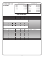
ELECTRICAL DATA
RU-150-12
RU-150-20
RU-225-12
RU-225-20
RU-300-12
RU-300-28
RU-300-20
RU-600-12
RU-600-28
RU-600-20
RU-1000-12
RU-1000-20
MODEL
1
3
1
3
1
1
3
1
1
3
1
3
220
208/220
220
208/220
220
220
208/220
220
208/220
208/220
220
208/220
3W+GND
3WOR4W+GND
3W+GND
3WOR4W+GND
3W+GND
3W+GND
3WOR4W+GND
3W+GND
3W+GND
3WOR4W+GND
3W+GND
3WOR4W+GND
23
15
32
21
27
36
21
46
38
29
46
29
5KW
5.25KW
7KW
7.5KW
6KW
8KW
7.5KW
10KW
8KW
10.5KW
10KW
10.5KW
1- WC-913-01 220V,5KW
1- WC-907-01 220V,1.75KW LEFT
1- WC-907-02 220V,1.75KW CENTER
1- WC-907-03 220V,1.75KW RIGHT
1- WC-911-01 220V,3.5KW
1- WC-911-02 220V,3.5KW
1- WC-908-01 220V,2.5KW LEFT
1- WC-908-02 220V,2.5KW CENTER
1- WC-908-03 220V,2.5KW RIGHT
2- WC-910 220V,3KW
2- WC-912 220V,4KWEA.
3- WC-908 220V,2.5KWEA.
2- WC-913 220V,5KWEA.
2- WC-912 220V,4KWEA.
3- WC-911 220V,3.5KWEA.
2- WC-913 220V,5KWEA.
3- WC-911 220V,3.5KWEA.
ELEMENTSWIRESVOLTS WATTS AMPS PHASE

13

14

15

16
TROUBLESHOOTING
To help the service technicians in the eld to
understand the operation of the RU models, we
separate the basic functions of the unit into four
different areas:
1. Heat Supply
2. Water Level Control
3. Brewing Cycle
4. Aeration
These four functions, even though they utilize
the same power supply, work independently from
each other.
In the following illustrations, problems are isolated
to only that system where a malfunction is locat-
ed, so in the eld or shop, you will know exactly
what components are involved.
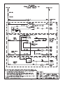
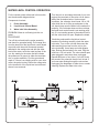
HEAT SUPPLY OPERATION
For the contact points referenced in this section,
see the schematic diagram below.
Components involved:
1. Power Block
2. Thermostat
3. Heating Elements
HEAT SUPPLY
PROBLEM: Water will not heat up or heats up
too slowly.
PROCEDURE: Take a voltage reading at termi-
nals L1 and L3 of the power block (marked A & A)
and if there is current at the power block.
If there is power, turn the thermostat all the way
to boil and clamp your ammeter around heating
element wire at point B shown in the single phase
diagram below. The reading should be approxi-
mately the same as indicated in the serial plate of
the machine.
If the meter reads only half of the amps that
your urn is rated at (check serial plate), one of
the heating elements has burnt out. Clamp your
ammeter at points C to determine which of the
heating elements is bad. Replace the heating ele-
ment.
If the water temperature in the urn is too hot (boil-
ing) or too cold when the pilot light goes out, the
thermostat must be calibrated. Reset the thermo-
stat calibration, refer to the steps on page 10.
If the thermostat will not hold a calibration, re-
place the thermostat.

17
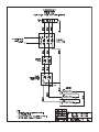
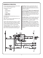
Turn the unit on and clamp the leads of your volt-
meter at the terminals of the valve coil as shown
at B of the illustration below. Under normal
conditions, the voltmeter should read 110 to 120
volts while the urn is lling up and power to the
coil should stop once the water level reaches the
probe tip. If the voltmeter does not show voltage,
the liquid level control board is not working prop-
erly. It is not sending power to the solenoid valve
and the valve does not open. Replace the board.
If both the probe and the liquid level control
board are functioning normally, check the water
inlet valve. Turn on the unit and disconnect the
white and the blue wires from the coil on the
valve (points B). Use a lamp cord with alligator
clips; hookup the terminals to the cord. Plug the
cord into a 120 volt outlet. The valve should open
when plugged in and close when unplugged.
Repeat this three or four times. If you don’t hear
the sound of the solenoid, then the coil is bad. If
you hear water owing through the valve when
unplugged, the diaphragm is either torn or needs
cleaning. Replace the water inlet valve.
For the contact points referenced in this section,
see the schematic diagram below.
Components Involved:
1. Probe Assembly
2. Liquid Level Control Board
3. Water Inlet Valve Assembly
PROBLEM: Water is not owing into the urn
jacket.
PROCEDURE:
Turn off the unit and test the probe assembly
and check for grounded wiring. Pull orange wire
from the terminal of the liquid level control board
at point A, with the quick disconnect terminal
attached to the orange wire and with the other
lead of the meter, touch the metal surface of the
urn. Any reading in the meter dial will indicate
the presence of a ground in either the terminals,
wire, or probe assembly. Find the ground and
repair it. If there is no reading at all on your ohm-
meter, the probe is okay. Return the orange wire
to the terminal 4 of the liquid level control board
where it was removed.
WATER LEVEL CONTROL OPERATION

18
A
D
E
C
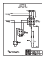
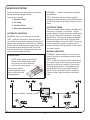
BREWING OPERATION
For the contact points referenced in this section,
see the schematic diagram below.
Components Involved:
1. Fuse
2. Brew Switch
3. Timer
4. Stop Switch
5. Water Pump
PROBLEM: Brew switch light does not turn on
when pressed.
Test: Check your power supply and fuse in con-
trol box. It may be burned out.
Problem: Brew switch does not stay on, or light
stays on only while switch is pressed but turns
off when released and water comes out of spray
head only while the switch is kept pressed.
Test Brew Switch: Take a voltage reading at
point A while the brew switch is pushed in. If you
read 110 volts, that means the switch is good.
Test Timer: The timer resets itself to the N. O.
position after every brewing cycle but if it fails
to stop itself, it will remain closed and cause the
problem in question.
To check the timer, power to the control circuit
must be turned off. Disconnect STP RED (point
B) and STP BRN (point C)wires and take a con-
tinuity test between the two terminals 8 and 9 on
the timer. If there is continuity, the timer is faulty
and must be replaced.
Test Water Pump: To test the water pump, press
the brew switch and take a voltage reading be-
tween points E and F. If there is voltage and the
pump does not run, replace the pump.
Test Stop Switch: The last of the components
involved in this operation is the stop button. The
only function of the switch is to interrupt the cur-
rent that energizes the timer after the brew switch
has been depressed. A voltage reading at N.O. of
the timer (point D) will indicate an open or closed
condition.

19
C
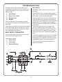
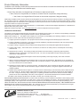
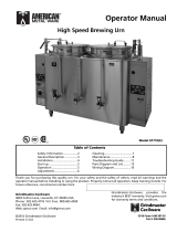
AERATION SYSTEM
For the contact points referenced in this section,
see the schematic diagram below.
Components Involved:
1. Aeration Tubes.
2. Air Pump
3. Aeration Timer
4. Manual Aeration Switch
AUTOMATIC AERATION
PROBLEM: Only one of the liners is aerated.
TEST: Inside the control box, there are two sili-
cone tubes connecting the aeration pump to the ¼”
copper tubes coming from inside the urn. Carefully,
pull the silicone tubes from the copper tubes, press
the manual aeration button and feel for air ow
from the silicone tubes. Replace the pump if air
does not blow through the tubes.
These are air release
holes that pump into the
liner so coffee can rell
the gauge glass.
NOTE: When replacing the silicone
tubing on the copper tubes, make
sure you do not cover the small
holes on the copper tubes.
PROBLEM: Aeration system fails to operate
automatically.
TEST: Determine that the aeration pump is
operating by pressing the manual aeration button
on the front panel to see that air comes from the
tubes.
AGITATION TIMER
Check the agitation timer. Remove the Black wire
from point A, terminal 1 on the timer. Discon-
nect the Black wire from the areator switch (point
B). Plug this wire into the terminal 1 of the timer
(dashed line). The air pump should immediately
start pumping air into the liner. If this test fails,
replace the agitation timer WC-405R. If the pump
runs normally, then replace the wires to their
proper connections and proceed to test the aera-
tion switch, below.
MANUAL AERATION
PROBLEM: Manual aeration is not present on
either of the liners, yet automatic aeration oper-
ates normally.
TEST: Check the continuity of the manual aera-
tion switch. Power to the control circuit must be
turned off to check for continuity. Check at the
YELLOW wire at point C of the agitation timer
and B (BLACK wire) of the manual aeration
switch. Press the switch to look for continuity.
Check for clean, tight connections at all termi-
nals.
Air Pump Tubes.

20
PrintedinU.S.A.9/2014F-1950revD
ECN 16033 . 7/24/14 @ 13.0 . rev D . V6
ecn 13345 . 7/18/[email protected] . revC
ecn 9894 . 10/15/8 . 14.8 . rev B
18/22/03 . 16.0 revAX WILBUR CURTIS CO., INC.
6913AccoSt.,Montebello,CA90640-5403USA
Phone:800/421-6150(M-F5:30A-4:00PPST) Fax:323-837-2410
TechnicalSupportPhone:800/995-0417 E-Mail:[email protected]
WebSite:www.wilburcurtis.com
Product Warranty Information
The Wilbur Curtis Company certies that its products are free from defects in material and workmanship under normal use.
The following limited warranties and conditions apply:
3 Years, Parts and Labor, from Original Date of Purchase on digital control boards.
2 Years, Parts, from Original Date of Purchase on all other electrical components, ttings and tubing.
1 Year, Labor, from Original Date of Purchase on all electrical components, ttings and tubing.
Additionally, the Wilbur Curtis Company warrants its Grinding Burrs for Forty (40) months from date of purchase or 40,000 pounds of cof-
fee, whichever comes rst. Stainless Steel components are warranted for two (2) years from date of purchase against leaking or pitting
and replacement parts are warranted for ninety (90) days from date of purchase or for the remainder of the limited warranty period of the
equipment in which the component is installed.
All in-warranty service calls must have prior authorization. For Authorization, call the Technical Support Department at 1-800-995-0417.
Effective date of this policy is April 1, 2003.
Additional conditions may apply. Go to www.wilburcurtis.com to view the full product warranty information.
CONDITIONS & EXCEPTIONS
The warranty covers original equipment at time of purchase only. The Wilbur Curtis Company, Inc., assumes no responsibility for substitute
replacement parts installed on Curtis equipment that have not been purchased from the
Wilbur Curtis Company, Inc. The Wilbur Curtis Company will not accept any responsibility if the following conditions are not met. The
warranty does not cover and is void under the following circumstances:
1) Improper operation of equipment: The equipment must be used for its designed and intended purpose and function.
2) Improper installation of equipment: This equipment must be installed by a professional technician and must comply with all
local electrical, mechanical and plumbing codes.
3) Improper voltage: Equipment must be installed at the voltage stated on the serial plate supplied with this equipment.
4) Improper water supply: This includes, but is not limited to, excessive or low water pressure, and inadequate or uctuating
water ow rate.
5) Adjustments and cleaning: The resetting of safety thermostats and circuit breakers, programming and temperature
adjustments are the responsibility of the equipment owner. The owner is responsible for proper cleaning and regular
maintenance of this equipment.
6) Damaged in transit: Equipment damaged in transit is the responsibility of the freight company and a claim should be
made with the carrier.
7) Abuse or neglect (including failure to periodically clean or remove lime accumulations): Manufacturer is not responsible for
variation in equipment operation due to excessive lime or local water conditions. The equipment must be maintained accord-
ing to the manufacturer’s recommendations.
8) Replacement of items subject to normal use and wear: This shall include, but is not limited to, light bulbs, shear disks, “0”
rings, gaskets, silicone tube, canister assemblies, whipper chambers and plates, mixing bowls, agitation assemblies and
whipper propellers.
9) Repairs and/or Replacements are subject to our decision that the workmanship or parts were faulty and the defects showed
up under normal use. All labor shall be performed during regular working hours. Overtime charges are the responsibility of
the owner. Charges incurred by delays, waiting time, or operating restrictions that hinder the service technician’s ability to
perform service is the responsibility of the owner of the equipment. This includes institutional and correctional facilities.
The Wilbur Curtis Company will allow up to 100 miles, round trip, per in-warranty service call.
RETURN MERCHANDISE AUTHORIZATION: All claims under this warranty must be submitted to the Wilbur Curtis Company Techni-
cal Support Department prior to performing any repair work or return of this equipment to the factory. All returned equipment must be
repackaged properly in the original carton. No units will be accepted if they are damaged in transit due to improper packaging. NO
UNITS OR PARTS WILL BE ACCEPTED WITHOUT A RETURN MERCHANDISE AUTHORIZATION (RMA). RMA NUMBER MUST BE
MARKED ON THE CARTON OR SHIPPING LABEL. All in-warranty service calls must be performed by an authorized service agent.
Call the Wilbur Curtis Technical Support Department to nd an agent near you.
-
 1
1
-
 2
2
-
 3
3
-
 4
4
-
 5
5
-
 6
6
-
 7
7
-
 8
8
-
 9
9
-
 10
10
-
 11
11
-
 12
12
-
 13
13
-
 14
14
-
 15
15
-
 16
16
-
 17
17
-
 18
18
-
 19
19
-
 20
20


Curtis RU-600 User manual
- Category
- Coffee makers
- Type
- User manual
Ask a question and I''ll find the answer in the document
Finding information in a document is now easier with AI
Related papers
Other documents
-
 Wilbur Curtis Company RU-600 User manual
-
Cecilware FE300 Operating instructions
-
American Metal Ware FE100N 3 PHASE Operating instructions
-
-
-
-
Crathco / Grindmaster 7444E Operating instructions
-
American Metal Ware 8106E Operating instructions
-
 American Metal Ware PB-8113E Operating instructions
-
 American Metal Ware High Volume, High Speed Urn Operating instructions


