Page is loading ...


2

EmotivaX‐SeriesAmplifiers–TableofContents
SAFETYPRECAUTIONS 5
NEC(NationalElectricalCode)Standards
ANotefortheCableTelevision(CATV)Installer
AntennaGroundingOutsidetheHouse
7
7
7
ThankYouForYourPurchase 8
EmotivaX‐SeriesAmplifiersOverview 9
X‐SeriesAmplifierFeatures 10
PowerRatingNote 10
UnpackingYourXSeriesAmplifier
Inventory
11
11
FrontPanelLayout 12
BackPanelLayouts
XPA‐1BackPanel
XPA‐2BackPanel
XPA‐3BackPanel
XPA‐5BackPanel
13
13
15
17
19
InstallationandConnections
ACPowerConsiderations
PhysicalPlacement/HeatConsiderations
InputConnectionConsiderations
OutputConnectionConsiderations
ConnectionTipsforSuperiorSound
22
22
22
23
23
23
ConnectionDiagram 24
ConnectionusingaMulti‐ChannelPreamp/Processor 25
SeriesandParallelSpeakerConnections 26
SeriesConnections 26
ParallelConnections 27
TechnicalNoteaboutMultipleSpeakerConnections 27
TableofContentscontinues,nextpage
3

TroubleshootingGuide
NoSound(fromoneormorespeakersconnectedtotheamplifier)
Theamplifiershutsdownoftenorthelinecircuitbreakertripsoften
PoorBassPerformanceFromFullRangeSpeakersconnectedtotheamplifier
Turn‐onandturn‐offthumps
“Hum”NoisesintheSpeakers
OtherProbableCausesofNoise
OneormoreREDlightsontheFrontPanelareBlinking
ProblemswiththewholeA/VSystem
28
28
28
29
29
29
30
30
30
TECHNICALSPECIFICATIONS
XPA‐1Specifications
XPA‐2Specifications
XPA‐3Specifications
XPA‐5Specifications
31
31
32
33
34
LimitedWarranty 35
ServiceAssistance 35
EmotivaDisclosure 36
4

SafetyPrecautions
ReadthisUser’sGuidethoroughlybeforeattemptingtoinstallandconfigureXSeriesAmplifier.Allthesafetyandoperation
instructionsshouldbereadbeforeanyoperationofthecomponent(s)begin.Aftersuccessfulinstallationandconfiguration
oftheamplifier,besuretoretainthismanualinasafeplaceforanyfuturereferenceneeds.
Thefollowingsituatio
• Thepower‐supplycordortheplughasbeendamaged;or
• TheXSeriesAmplifierhasbeenexposedtorain;or
heXSeriesAmplifierdoesnotappeartooperatenormallyorexhibitsamarkedchangeinperformance;or
heXSeriesAmplifierhasbeendropped,oritsenclosureorchassisisdamaged.
heusershouldnotattempttoservicetheXSeriesAmplifierbeyondthemeansdescribedinthisOperationManual.
AllwarningontheamplifierandinthisOperationManualshouldbefollowed.Safetyisakeycomponent
toalonglasting,troublefreeinstallation.Thevastmajorityofthesafetyprecautionsaresimplycommon
sense.Ifyoudon'tfeelcomfortableperformingtheinstallationofaudio/videoentertainmentequipment,
itisadvisedthatyouseektheservicesofaqualifiedinstallationprofessional.
NEVERuseXSeriesamplifiersnearwatersuchasabathtub,washbowl,kitchensink,laundrytub,inawet
basement,ornearaswimmingpool,etc.Thereisariskofelectricshocktoyourbodyandpermanentdamagetothe
equipment.Electricshockmayresultinpermanentbodilyinjuryordeath.
Thisamplifiershouldbeinstalledinalocationwhichprovidesadequateventilation.Theamplifiershouldnotbeinstalledon
abed,sofa,rug,orothersimilarsurfacesthatwouldblockanyoftheventilationopenings;norshouldtheamplifierbe
installedinaclosedenvironmentthatmayimpedeairflowthroughtheventilationopeningsontheamplifier.Shouldyou
choosetoinstalltheamplifierinaclosedequipmentrackbesuretoaddforcedairventilationtoprovideadequateair
circulation.Theamplifiershouldbesituatedawayfromheatsourcessuchasradiatorsorotherheatproducingdevices.
EmotivaamplifiersshouldbeconnectedonlytoapowersupplyasdescribedinthisOperationManualorshownonthelabel
locatedonthebackoftheamplifier.Thepowercordshouldberoutedsothatitavoidshighfoottrafficareas;and,placement
ofthepowercordshouldavoidlocationswhereheavyitemsmaybeplaceuponoragainstit.Specialattentionshouldbe
givenwherethepowercordwillplugintothewalloutlet,conveniencereceptacles,andthepointwherethepowercord
attachestoXSeriesAmplifier.
Thepowercordoftheamplifiershouldbeunpluggedfromtheoutletwhenunusedforalongperiodoftime.Neverspray
liquidsdirectlyintothecomponent’sventopenings.Careshouldbetakensothatsmallobjectsdonotfallintotheinsideof
theamplifier.
nsrequireyourEmotivaXSeriesAmplifierisservicedonlybyqualifiedservicepersonnel:
Objectshavefallen,orliquidhasspilledintothecomponent;or
• T
• T
T
AllotherservicingshouldbereferredtoEmotiva'sservicepersonnel.
5

Topreventelectricshock,donotusethispolarizedplugwithanextensioncord,receptacleor
otheroutletunlessthebladescan befullyinsertedtopreventbladeexposure.
GroundingorPolarization—Precautionsshouldbetakensothatthegroundingorpolarization
meansofthecomponentisnotdefeated.
ThisapparatusdoesnotexceedtheClassA/ClassB(whicheverisapplicable)limitsforradionoiseemissionsfromdigital
apparatusassetoutintheradiointerferenceregulationsoftheCanadianDepartmentofCommunications.
Forquestionsregardingservice,pleasecontact:
EMOTIVATollFree–877‐EMO‐TECH
www.emotiva.com
WARNING:TOREDUCETHERISKOFFIREORELECTRICSHOCK,DONOTEXPOSETHIS
APPLIANCETORAINORMOISTURE.
CAUTION:TOPREVENTELECTRICSHOCK,MATCHWIDEBLADEOFPLUGTO
WIDESLOT,FULLYINSERT.
6

NEC(NationalElectricalCode)Standards
ANotefortheCableTelevision(CATV)Installer
ThisreminderistocalltheCATVsysteminstaller’sattentiontoArticle820‐40oftheNECthatprovidesguidelinesforproper
groundingandinparticular,specifiesthatthecablegroundshallbeconnectedtothegroundingsystemofthebuildingas
closetothepointofcableentryaspractical.
AntennaGroundingOutsidetheHouse
Ifanoutsideantennaisconnectedtothereceiver,besuretheantennasystemisgroundedsoastoprovidesomeprotection
againstvoltagesurgesandbuilt‐upstaticcharges.Article810oftheNationalElectricalCode,ANSI/NFPA70,provides
informationwithregardtopropergroundingofthelead‐inwiretoanantenna‐dischargeunit,connectiontogrounding
electrodes,andrequirementsforthegroundingelectrode.
Alwaysobserveproperantennaorsatellitedishgroundingtechniques.Whenlightningstrikesthereisalwaysthepossibility
thatyourantennaordish(mountedhighontheroof)canbecomeaconduitforlightningandelectricallydamageany
equipmenttowhichit’sconnected.Additionally,propergroundingofferssafetytothepeopleusingtheaudio/videosystem
intheeventofanelectricalproblem.
7

ThankYouforyourPurchase
We’rehappyyouchoseEmotivaAudio!Webelieveourproductssetanewstandardforperformanceandvalue.
Emotivaamplifiersaredesignedformaximumperformance,easeofuse,andsimpleinstallation.Ourexperiencedengineers
usepractical,provendesigns,alongwithinnovativeideastocreateamplifiersthatwilleasilypoweryourspeakersatanylevel
whileremainingasefficientaspossible.Enjoyaudioandvideosourceswithoutconcernfordynamicheadroomduring
complexmusicalpassagesandhigh‐leveleffects–andwithasoundqualitythatwillsatisfythemostdiscriminatinglistener.
Ouramplifiersarebuiltfordecadesofreliableuse,withafullfiveyearwarrantyonallpartsandlabor.Ourstaffisaphone
callaway,readytoassistyouifneeded.Westandbehindourproducts100percent,andweknowthatearningyourtrustand
patronagedependsonourcontinuingcommitmenttoexcellenceineveryway.
Emotivastartedwithanidea–theideaofaudioenthusiastsbuildinggearthatsatisfiedtheirownhighstandards,andsharing
itwithfellowenthusiasts,withnooneinthemiddle.Justthebestpossiblegearatthebestpossibleprices,directtoyou.
WewishyoumanyhoursofenjoymentwithyourEmotivapurchase.Welcometothefamily!
DanLaufman,
President,EmotivaAudioCorporation
8

EmotivaXSeriesAmplifiersOverview
TheXseriesamplifiersweredesignedformultipleapplications,andworkwellinbothhometheaterandmusicalsettings.
Theywereengineeredtobehighlyresponsive,dynamicanddeliveraclear,neutralandnaturalsound.
XPA‐1
Thisamplifierworksextremelywellforstereouse(requirestwoamplifiers),andoffersanextremelydynamichometheater
experience–tonsofpowerwhileretaininganopen,relaxedsoundmilesawayfromlisteningfatigue.
Fullybalancedwithaquaddifferentialinputstageandadiscretefrontend.Itfeatures24outputdevicesanddelivers500
wattsinto8ohms,and1,000into4ohms.TheXPA‐1isforseriousaudiophileswhowantaverydetailed,cleansound.
Recommendedforleftandrightchannels,left,right,andcenterchannels,orallchannels(oneamplifierperchannel)
XPA‐2
Thistwochannelamplifierpacksapunchaseitherastand‐alonestereoamplifier,orasanamplifierfortheleftandright
channelsinyourhometheater.CombiningitwithanXPA‐5makesaformidable7channelsystem.
TheXPA‐2boastsalargertransformerthantheXPA‐5orXPA‐3,aswellasmoresecondarycapacitance,largerpower
modulesandhigherrailvoltage.Anextremelyrobustoutputsection(12outputdevices)maximizespoweranddelivers
exceptionalperformance.
Ratedat250wattsinto8ohms,500wattsinto4ohms(minimumrating–itwillpeakhigher).TheXPA‐2isalsobridgeable
(for8ohmloads),transformingitintoapotentmonoblock.
XPA‐3
TheXPA‐3wasbroughttotheXfamilyasa‘turbocharger’fortheaveragereceiver.Simplyput,areceiver’samplifiercannot
competewithaseparateamp.It’sjustsimplyphysics,duetothespacelimitationswithinthereceiver.
TheXPA‐3ratesat200wattsperchannel(8ohms),andwasdesignedtobeusedtopowertheleft,rightandcenterchannels,
givingthereceiverenoughbreathingspacetoadequatelypowerthesurrounds.Ofcourse,itcanbeusedwithother
amplifiersinvariousconfigurations,withorwithoutusingareceiver.
XPA‐5
ThefirstXseriesamplifier,andstillthemostpopular.Thisfivechannelamplifierwastheanswertotheconstantrequestfor
‘moreheadroom,please’.Anamplifierwith‘headroom’hasapowersupplycapableofpeakingwellbeyonditscontinuous
rating,makingitextremelydynamic,whileretainingclearimaginganddetail.
At200wattsinto8ohms(300into4ohms),theXPA‐5immediatelyraisedthebarandbecameaclassic.Thebackboneofa
serioushometheaterandstereosystem,andeasilycombinedwithanXPA‐2foranabsoluteknockoutofa7channelsetup.
9

X Series Amplifier Features:
• Audiophile quality performance and sound
• High current power supply
• Low noise toroidal power transformer
• Complementary, discrete power amplifier design incorporating high current, high speed,
On Semiconductor power devices
• Channel status indicators for standby, operate, and fault
• 12 volt trigger connections
• Completely stable into 4 ohm loads
• Signal to Noise Ratio is greater than 100dB, unweighted ref. full output
• THD .03% at rated power, 20Hz – 20kHz
• Fully protected from all fault conditions
• Soft start circuitry
• External trigger turn on
• Soft touch power switch
• Heavy duty, rack standardized chassis w/ solid milled aluminum faceplate
• IEC power inlet, 115/230 VAC Auto configurable
Power Rating Note: ‘Peak’ vs. ‘Continuous’
Many companies will rate an amplifier with only one or two channels driven under load, which results† in† inflated rating of the
power output. In real life, this will drop significantly when all channels are driven. This is called ‘peak’ power conditions (Peak
Music Power Output, or PMPO). ‘Peak power’ represents the maximum amount of power that an amplifier/receiver can
deliver without being damaged. Ratings are performed this way for the sole reason of exaggerating the perceived power of
the product, and during normal use, the actual practical power output is much lower than the claimed ‘peak’ rating.
Sometimes these ratings are also performed at 10% THD, even thought the industry accepted level is 1.0% THD. This practice
has led many people to seek higher and higher levels of power in amplifiers because they misunderstand the difference
between ‘peak’ and ‘continuous’ power.
All Emotiva amplifiers are rated for continuous power, tested with all channels driven simultaneously. We do not play games
with the specifications, and test all of our amplifiers to industry standard test conditions with the amplifier put under the
strictest loads. This means that the power output and other specifications listed are the bare minimum (or worst case
scenario) you will receive from our amplifiers. Under normal circumstances you will get much higher output then what is
rated.
The bottom line is this: These amplifiers are powerful, and can give you control over your sound in ways a receiver could
never come close to. We’re proud to offer amazing performance to match the amazing value of the X Series amplifiers.
10

Unpacking Your X Series Amplifier
All Emotiva amplifiers are double boxed to survive the rigors of long distance shipping and arrive to you undamaged. The
outer box may show wear and tear, but this is no cause for alarm. The outer box’s purpose is to protect the inner box. If the
inner looks heavily damaged, and you are concerned about damage to the amplifier, please call Emotiva Technical Support at
877‐366‐8324 (877‐EMO‐Tech). Inside the laminated inner box, the amplifier is securely seated between to two reinforced
pieces of high‐density impact foam. At first glance, the cardboard backing on the foam may give the appearance of a third
box, but it is easily lifted to reveal the amplifier, which is wrapped in static free plastic. The plastic sheeting is tucked
underneath the amplifier and securely taped. It is recommended that the plastic sheeting be removed after the amp is lifted
out from the box. The bottom piece of foam is molded to fit tightly against the amplifier, but there is a recessed area on each
side, allowing you to get your hands under the amplifier and lift it out of the box.
Note: These amplifiers are HEAVY! Lift with your legs!
Inventory
Included with your X amplifier should be an IEC Class 1, 2 prong power cord, and this User’s Guide. Emotiva amplifiers are
double insulated and do not require a grounded plug. Much care has been taken to make sure that your amplifier is safe,
completely shielded, insulated and grounded. It is important to save all the packing materials and the box in case your X
amplifier ever needs to be moved or shipped for servicing.
11

FrontPanelLayout
ThefaceofanXPA‐5isshownabove.AlthoughthereisvariationwithintheX‐Seriesamplifiersfaceplates,thebasicfeatures
arethesame:apowerbuttonandLEDStatuswindow.
1.FrontPanelLEDDisplay
ThefrontpaneldisplaycontainsStatusLEDlightingtoindicatetheoperationstatusoftheamplifier.
• NOLED=AmplifierisOFF
• BLUELED=NormalOperation
• FLASHINGREDLED=FaultCondition‐see“Troubleshooting”sectionfordetails.
Note:ThebackpanelofeachamplifierhasanLEDStatusSelectorwhichcanturntheblueLEDsoff.
2.FrontPanelPowerSwitch
ThisswitchprovidestheON/OFFcontroloftheamplifierfromthefrontpanel.Whentheunitisoffandinstandbymode,the
switchilluminatesamber.Automaticswitchingisaccomplishedwiththe3.5mmtriggerinputonthebackpanelusinga5‐12V
DCcontrolsignal.
NoteOnAmplifierSupports:
Donotremovethesupportsor‘feet’fromyouramplifier.Inadditiontominimizingvibrationandinsulatingtheamplifier
fromthesurfaceitisplacedon,thesefeetareessentialinallowingairflowundertheamplifierforpropercooling.
12

Back Panel Layouts
XPA‐1 Back Panel
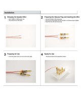
2. Negative Speaker Terminals – These 5 way binding posts accept stripped speaker wire, banana plugs, or spade
connectors. Be sure to observe correct polarity when connecting speakers and be sure that the wires do not touch between
positive and negative terminals. Both negative speaker terminals are electrically the same. When connecting a single
speaker, connect the negative terminal on the speaker to either negative terminal on the
amplifier. When bi-wiring a speaker, connect each negative speaker wire to one of the negative speaker terminals on the
XPA-1.
Note: Potentially lethal voltages present! Never connect, disconnect or change speaker wiring with the amplifier turned on.
3. Meter/LED Status Selectors – The status LED (single LED that lights when the unit is on) and meter LEDs (which move in
sync with the amplifier output) on the amplifier faceplate can be turned on or off with these selectors.
4. Remote Trigger Input/Output – The XPA‐1 can be remotely triggered by another device, and in turn, remotely trigger
another device. When a remote trigger output from a preamplifier, processor or other audio device is connected to the
trigger input here, the amplifier will power up and shut down along with the first device. Another device (CD player,
amplifier, etc) can be added to this chain using the trigger output. A 3.5mm, 5‐12 volt mono audio cable is used for both
inputs and outputs. If building your own cable, center is positive and outer shield is negative.
5. RCA Audio Input – Connects to the RCA output of a preamplifier or processor. This is marked ‘Un‐Bal’ because it is an
unbalanced connection.
13

6. Balanced/Unbalanced Input Selection Switch – When the switch is turned towards ‘Un‐Bal’, the RCA (unbalanced) input is
chosen and active. When the switch is turned towards ‘Bal’, the XLR/Balanced input is chosen and active.
7. XLR/Balanced Audio Input – Connects to the XLR/Balanced output of a preamplifier or processor.
8. Positive Speaker Terminals – These 5 way binding posts accept stripped speaker wire, banana plugs, or spade connectors.
Be sure to observe correct polarity when connecting speakers and be sure that the wires do not touch between positive and
negative terminals. Both positive speaker terminals are electrically the same. When connecting a single speaker, connect
the positive terminal on the speaker to either positive terminal on the amplifier. When bi-wiring a speaker, connect each
positive speaker wire to one of the positive speaker terminals on the XPA-1.
Note: Potentially lethal voltages present! Never connect, disconnect or change speaker wiring with the amplifier turned on.
9. IEC Power Cable Connection
10. Master Power Switch ‐ This rocker switch provides the master power for the amplifier. After it is in the ON position, the
amplifier can be turned on manually from the front panel switch or automatically with the trigger input via 3.5mm input jack.
Under normal use, this switch should remain on, leaving the amplifier in standby position, and coming to full power with
either the front panel ‘STANDBY’ button, or activation through the remote trigger. In ‘STANDBY’ mode the power button will
emit an amber glow, but the unit is not fully powered. A small amount of power is used in this mode, less than an average
night light would use. If you are away for an extended period of time (more than a few days), shut off all power to the
amplifier with the main power switch on the back of the amplifier.
11. Voltage Indicator – All Emoitva amplifiers operate on either 115V or 230V. The voltage is detected when the amplifier is
turned on, and is identified by the indicator lights. There are no user adjustments, the amplifier automatically adjusts to the
voltage.
14

XPA‐2 Back Panel
1. Remote Trigger Input ‐ The XPA‐2 can be remotely triggered by another device. When a remote trigger output from a
preamplifier, processor or other audio device is connected to the trigger input here, the amplifier will power up and shut
down along with the first device.
A 3.5mm, 5‐12 volt mono audio cable is used for both inputs and outputs. If building your own cable, center is positive and
outer shield is negative.
2. Working LED Selector – The two ‘On’ status LEDs (one for each channel) on the amplifier faceplate can be turned on and
off with this selector.
3. Meter LED Selector – The meter LEDs (which move in sync with amplifier output) can be turned on and off with this
selector.
4. Right Channel XLR/Balanced Input – Connects with an XLR/Balanced cable to the right channel output of a preamplifier or
processor.
5. Right Channel Balanced/Unbalanced Input Selector – When turned towards ‘Un‐Bal’, the RCA (unbalanced) input is
chosen and active. When turned towards ‘Bal’, the XLR/Balanced input is chosen and active.
6. Right Channel RCA /Unbalanced Input ‐ Connects with an RCA/Unbalanced cable to the right channel output of a
preamplifier or processor.
7. Bridged Configuration Selector – Leaving this selector on ‘OFF’ keeps the XPA‐2 in standard two channel mode. Turning it
to ‘ON” bridges the two separate channels into one, turning the XPA‐2 into a monoblock amplifier. NOTE: Bridged mode is
meant for use with 8 ohm speakers. Using bridged mode with lower impedence speakers may cause overheating, causing
the amplifier to go into protect mode (fault), and possibly sustain permanent damage.
8. Left Channel RCA /Unbalanced Input ‐ Connects with an RCA/Unbalanced cable to the left channel output of a
preamplifier or processor.
9. Left Channel Balanced/Unbalanced Input Selector – When turned towards ‘Un‐Bal’, the RCA (unbalanced) input is chosen
and active. When turned towards ‘Bal’, the XLR/Balanced input is chosen and active.
15

10. Left Channel XLR/Balanced Input ‐ Connects with an XLR/Balanced cable to the left channel output of a preamplifier or
processor.
11. Left Channel Speaker Terminals ‐ Connects to the left side speaker inputs. These 5 way binding posts accept stripped
speaker wire, banana plugs (single or dual), or spade connectors. Be sure to observe correct polarity when connecting
speakers and be sure that the wires do not touch between positive and negative terminals.
12. Right Channel Speaker Terminals‐ Connects to the right side speaker inputs. These 5 way binding posts accept stripped
speaker wire, banana plugs (single or dual), or spade connectors. Be sure to observe correct polarity when connecting
speakers and be sure that the wires do not touch between positive and negative terminals.
Note: Potentially lethal voltages present! Never connect, disconnect or modify speaker wiring with the amplifier turned
on.
Note: In BALANCED mode, connect the single speaker to the Left Channel + and Right Channel + speaker
terminals.
13. IEC Power Cable Connection
14. Master Power Switch ‐ This rocker switch provides the master power for the amplifier. After it is in the ON position, the
amplifier can be turned on manually from the front panel switch or automatically with the trigger input via 3.5mm input jack.
Under normal use, this switch should remain on, leaving the amplifier in standby position, and coming to full power with
either the front panel ‘STANDBY’ button, or activation through the remote trigger. In ‘STANDBY’ mode the power button will
emit an amber glow, but the unit is not fully powered. A small amount of amps are used in this mode, less than an average
night light would use. If you are away for an extended period of time (more than a few days), shut off all power to the
amplifier with the main power switch on the back of the amplifier.
15. Voltage Indicator ‐ All Emoitva amplifiers operate on either 115V or 230V. The voltage is detected when the amplifier is
turned on, and is identified by the indicator lights. There are no user adjustments, the amplifier automatically adjusts to the
voltage.
16

XPA‐3 Back Panel
1. Status LED Selector ‐ The three status LEDs (one for each channel) can be turned on and off with this selector.
2. Channel Three Balanced/Unbalanced Input Selector – When the switch is turned towards ‘Un‐Bal’, the RCA (unbalanced)
input is chosen and active. When the switch is turned towards ‘Bal’, the XLR/Balanced input is chosen and active.
3. Channel Three RCA Audio Input – Connects to the RCA output of a preamplifier or processor. This is the Channel Three
unbalanced connection.
4. Channel Three XLR/Balanced Input – Connects an XLR/Balanced cable to a preamplifier or processor. This is the Channel
Three balanced connection.
5. Channel Two Balanced/Unbalanced Input Selector – When the switch is turned towards ‘Un‐Bal’, the RCA (unbalanced)
input is chosen and active. When the switch is turned towards ‘Bal’, the XLR/Balanced input is chosen and active.
6. Channel Two RCA Audio Input – Connects to the RCA output of a preamplifier or processor. This the Channel Two
unbalanced connection.
7. Channel Two XLR/Balanced Input – Connects an XLR/Balanced cable to a preamplifier or processor. This is the Channel
Two balanced connection.
8. Channel One Balanced/Unbalanced Input Selector – When the switch is turned towards ‘Un‐Bal’, the RCA (unbalanced)
input is chosen and active. When the switch is turned towards ‘Bal’, the XLR/Balanced input is chosen and active.
9. Channel One RCA Audio Input – Connects to the RCA output of a preamplifier or processor. This the Channel One
unbalanced connection.
10. Channel One XLR/Balanced Input – Connects an XLR/Balanced cable to a preamplifier or processor. This is the Channel
One balanced connection.
11. Master Power Switch ‐ This rocker switch provides the master power for the amplifier. After it is in the ON position, the
amplifier can be turned on manually from the front panel switch or automatically with the trigger input via 3.5mm input jack.
17

Under normal use, this switch should remain on, leaving the amplifier in standby position, and coming to full power with
either the front panel ‘STANDBY’ button, or activation through the remote trigger.
In ‘STANDBY’ mode the power button will emit an amber glow, but the unit is not fully powered. A small amount of amps are
used in this mode, less than an average night light would use. If you are away for an extended period of time (more than a
few days), shut off all power to the amplifier with the main power switch on the back of the amplifier.
12. Remote Trigger Input ‐ The XPA‐3 can be remotely triggered by another device. When a remote trigger output from a
preamplifier, processor or other audio device is connected to the trigger input here, the amplifier will power up and shut
down along with the first device.
13. Channel Three Speaker Terminals ‐
This is nominally the Front Right speaker (although you may assign the channels
differently if you like).
These 5 way binding posts accept stripped
speaker wire, banana plugs
(single or dual)
,
or spade
connectors. Be sure to observe correct polarity when connecting speakers and be sure that the wires do not touch
between positive and negative terminals.
14. Channel Two Speaker Terminals ‐
This is nominally the Center speaker (although you may assign the channels
differently if you like).
These 5 way binding posts accept stripped
speaker wire, banana plugs
(single or dual)
,
or spade
connectors. Be sure to observe correct polarity when connecting speakers and be sure that the wires do not touch
between positive and negative terminals.
15. Channel One Speaker Terminals ‐
This is nominally the Front Left speaker (although you may assign the channels
differently if you like).
These 5 way binding posts accept stripped
speaker wire, banana plugs
(single or dual)
,
or spade
connectors. Be sure to observe correct polarity when connecting speakers and be sure that the wires do not touch
between positive and negative terminals.
Note: Potentially le thal voltages present! Never connect, disconnect or
change
speaker wiring with the amplifier turned
on.
16. IEC Power Cable Connection
17. Voltage Indicator ‐ All Emoitva amplifiers operate on either 115V or 230V. The voltage is detected when the amplifier is
turned on, and is identified by the indicator lights. There are no user adjustments, the amplifier automatically adjusts to the
voltage.
18

XPA‐5 Back Panel
1. Status Led Selector ‐ The three status LEDs (one for each channel) can be turned on and off with this selector.
2. Channel Five Balanced/Unbalanced Input Selector – When the switch is turned towards ‘Un‐Bal’, the RCA (unbalanced)
input is chosen and active. When the switch is turned towards ‘Bal’, the XLR/Balanced input is chosen and active.
3. Channel Five RCA Audio Input – Connects to the RCA output of a preamplifier or processor. This is the Channel Five
unbalanced connection.
4. Channel Five XLR/Balanced Input – Connects an XLR/Balanced cable to a preamplifier or processor. This is the Channel
Five balanced connection.
5. Channel Four Balanced/Unbalanced Input Selector – When the switch is turned towards ‘Un‐Bal’, the RCA (unbalanced)
input is chosen and active. When the switch is turned towards ‘Bal’, the XLR/Balanced input is chosen and active.
6. Channel Four RCA Audio Input – Connects to the RCA output of a preamplifier or processor. This is the Channel Four
unbalanced connection.
7. Channel Four XLR/Balanced Input – Connects an XLR/Balanced cable to a preamplifier or processor. This is the Channel
Four balanced connection.
8. Channel Three Balanced/Unbalanced Input Selector – When the switch is turned towards ‘Un‐Bal’, the RCA (unbalanced)
input is chosen and active. When the switch is turned towards ‘Bal’, the XLR/Balanced input is chosen and active.
9. Channel Three RCA Audio Input – Connects to the RCA output of a preamplifier or processor. This is the Channel Three
unbalanced connection.
10. Channel Three XLR/Balanced Input – Connects an XLR/Balanced cable to a preamplifier or processor. This is the Channel
Three balanced connection.
11. Channel Two Balanced/Unbalanced Input Selector – When the switch is turned towards ‘Un‐Bal’, the RCA (unbalanced)
input is chosen and active. When the switch is turned towards ‘Bal’, the XLR/Balanced input is chosen and active.
19

12. Channel Two RCA Audio Input – Connects to the RCA output of a preamplifier or processor. This is the Channel Two
unbalanced connection.
13. Channel Two XLR/Balanced Input – Connects an XLR/Balanced cable to a preamplifier or processor. This is the Channel
Two balanced connection.
14. Channel One Balanced/Unbalanced Input Selector – When the switch is turned towards ‘Un‐Bal’, the RCA (unbalanced)
input is chosen and active. When the switch is turned towards ‘Bal’, the XLR/Balanced input is chosen and active.
15. Channel One RCA Audio Input – Connects to the RCA output of a preamplifier or processor. This is the Channel One
unbalanced connection.
16. Channel One XLR/Balanced Input – Connects an XLR/Balanced cable to a preamplifier or processor. This is the Channel
One balanced connection.
17. Master Power Switch ‐ This rocker switch provides the master power for the amplifier. After it is in the ON position, the
amplifier can be turned on manually from the front panel switch or automatically with the trigger input via 3.5mm input jack.
Under normal use, this switch should remain on, leaving the amplifier in standby position, and coming to full power with
either the front panel ‘STANDBY’ button, or activation through the remote trigger.
In ‘STANDBY’ mode the front panel button will emit an amber glow, but the unit is not fully powered. A small amount of
amps are used in this mode, less than an average night light would use.
If you are away for an extended period of time (more than a few days), shut off all power to the amplifier with the main
power switch on the back of the amplifier.
18. Remote Trigger Input ‐ The XPA‐3 can be remotely triggered by another device. When a remote trigger output from a
preamplifier, processor or other audio device is connected to the trigger input here, the amplifier will power up and shut
down along with the first device.
19. Channel Five Speaker Terminals ‐ This is nominally the Front Right speaker (although you may assign the channels
differently if you like). These 5 way binding posts accept stripped speaker wire, banana plugs (single or dual), or spade
connectors. Be sure to observe correct polarity and avoid short circuits and loose connections.
20. Channel Four Speaker Terminals ‐ This is nominally the Right Surround speaker (although you may assign the channels
differently if you like). These 5 way binding posts accept stripped speaker wire, banana plugs (single or dual), or spade
connectors. Be sure to observe correct polarity and avoid short circuits and loose connections.
21. Channel Three Speaker Terminals ‐ This is nominally the Center speaker (although you may assign the channels
differently if you like). These 5 way binding posts accept stripped speaker wire, banana plugs (single or dual), or spade
connectors. Be sure to observe correct polarity and avoid short circuits and loose connections.
22. Channel Two Speaker Terminals ‐ This is nominally the Left Surround speaker (although you may assign the channels
differently if you like). These 5 way binding posts accept stripped speaker wire, banana plugs (single or dual), or spade
connectors. Be sure to observe correct polarity and avoid short circuits and loose connections.
23. Channel One Speaker Terminals ‐ This is nominally the Front Left speaker (although you may assign the channels
differently if you like). These 5 way binding posts accept stripped speaker wire, banana plugs (single or dual), or spade
connectors. Be sure to observe correct polarity and avoid short circuits and loose connections.
Note: Potentially lethal voltages present! Never connect, disconnect or change speaker wiring with the amplifier turned on.
20
/