Page is loading ...

Operation Manual
GTi – Suction Feed Spraygun
E
E P 2 - 7 DA
DA
P 8 - 13
SV
SV P 14– 19
SB-E3-2-361 ISS.05

2
© 2007 ITW Finishing Systems and Products
Declaration of Conformity
We, ITW Finishing Systems and Products, Ringwood Road Bournemouth
Dorset England declare under our sole responsibility that this product is in
conformity with BS EN 292: parts 1 and 2 :1991 and BS EN 1953:1999,
following the provisions of the Machinery Directive 89/392/EEC. This product
also complies with the requirements of the EPA guidelines, PG6/34. Transfer
efficiency certificates are available on request.
B. Holt, General Manager
Operation Manual
GTi – Suction Feed Spraygun
Important
Read and follow all instructions and Safety Precautions before using this
equipment
Description
This product is suitable for use with both waterbased and solvent based
coating materials. The design uses EPA compliant atomising technology to
reduce overspray and improve coating efficiency.
Important: These guns are not designed for use with highly corrosive and/
or abrasive materials and if used with such materials it must be expected
that the need for cleaning and/or replacement of parts will be increased. If
there is any doubt regarding the suitability of a specific material contact
your local Distributor or ITW Finishing direct.
E
E
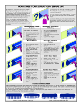
Model Part Number
Example: GTI-S110B-14
Aircap Fluid nozzle size
(14 = 1,4 mm)
Gunbody Finish
B= Blue Anodised
ITW Finishing Systems and Products reserve the right to modify equipment
specification without prior notice.

3 © 2007 ITW Finishing Systems and Products
SAFETY WARNINGS
Fire and explosion
Solvents and coating materials
can be highly flammable or
combustible when sprayed. ALWAYS
refer to the coating material suppliers
instructions and COSHH sheets
before using this equipment
Users must comply with all local
and national codes of practice and
insurance company requirements
governing ventilation, fire precautions,
operation and house-keeping of working
areas
This equipment, as supplied, is
NOT suitable for use with
Halogenated Hydrocarbons.
Static Electricity can be generated by
fluid and/or air passing though hoses. To
prevent such a risk, earth continuity to
the spray equipment and the object
being sprayed should be maintained.
Personal Protective
Equipment
Toxic vapours – When sprayed,
certain materials may be
poisonous, create irritation or be
otherwise harmful to health.
Always read all labels and safety data
sheets for the material before spraying
and follow any recommendations. If In
Doubt, Contact Your Material Supplier
The use of respiratory protective
equipment is recommended at
all times. The type of equipment
must be compatible with the
material being sprayed
Always wear eye protection when
spraying or cleaning the spraygun
Gloves must be worn when
spraying or cleaning the
equipment
Training – Personnel should be given
adequate training in the safe use of
spraying equipment.
Misuse
Never aim a spraygun at any part of the
body
Never exceed the max. recommended
safe working pressure for the equipment
The fitting of non-recommended or non-
original spares may create hazards
Before cleaning or maintenance, all
pressure must be isolated and relieved
from the equipment
The product should be cleaned using a
gun washing machine. However, this
equipment should not be left inside gun
washing machines for prolonged periods
of time.
Noise Levels
The A-weighted sound level of
sprayguns may exceed 85 dB
(A) depending on the set-up
being used. Details of actual
noise levels are available on request. It is
recommended that ear protection is worn
at all times when spraying
E
E

4
© 2007 ITW Finishing Systems and Products
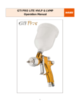
* - * Denotes Aircap Number - Available Aircaps No’s 105 and 110
** - ** Denotes Fluid Tip Size -
Available Sizes; GTI-213 0.85, 1.0, 1.1, 1.2, 1.3,1.4,1.5 mm
GTI-214 1.6, 1.8, 2.0 and 2.2 mm
+ - Parts included in service Kit (see accessories)
Parts List
Ref. No Description Part Number Qty
*1 Air Cap/Retaining ring GTI-407-* 1
1a Spring Clip JGA-156-K5 1
+**2 Nozzle (up to 1.5 mm) GTI-213-**-K 1
Nozzle (1.6 mm to 2.2 mm) GTI-214-**-K 1
3 Baffle & Seal GTI-425-K 1
Baffle seal—Kit of 5 GTI-33-K5 1
+4 Spring Adjusted Needle Packing GTI-445-K2 1
5 Spreader Valve GTI-405-K 1
6 Stud and Screw GTI-408-K5 1
+7 Needle (for GTI-214 Tip) GTI-420-K 1
Needle (for GTI-213 Tip) GTI-413-K 1
+8 Spring and Pad GTI-409-K5 1
9 Bushing GTI-402-K 1
9a Seal kit of 5 JGS-72-K5 1
10 Needle Adjusting Screw GTI-414-K 1
11 Valve Assembly JGK-449 1
12 Trigger GTI-108 1
13 Connector JGA-158 1
14 Airflow Valve GTI-415-K 1
15 Lock Nut JGA-51-K5 1
16 Seal 23165-001 1
17 Fluid Inlet Connector and seal JGA-159-K 1
18 Cup lid assembly KR-4001-B 1
19 Lid Gasket - kit of 3 KR-11-K3 1
20 Drip free diaphragm—kit of 5 KR-115-K5 1
21 Cup - Blue anodised KRW-401-K 1
22 Cup - Blue anodised KRW-502-B 1
23 Circlip 25746-007-K5 1
24 Circlip 2
25 Seal & Pin Kit GTI-428-K5 2
26 Air valve stem assembly 1
27 Spring JGV-262-K5 1
28 Spanner SPN-5 1
E
E

5 © 2007 ITW Finishing Systems and Products
Specification
Air supply connection - Universal 1/4 BSP and NPS
Fluid Supply Connection - Universal 3/8 BSP and NPS
Maximum static inlet pressure - P1 = 9 bar (130 psi)
Maximum static fluid pressure - P2 = 9 bar (130 psi)
Nominal gun inlet pressure with gun triggered - 2 bar (29 psi)
Gun Weight - 500 g
Cup Weight - 460g
Materials of Construction
Gun body - Anodised or Nickel Plated Aluminium
Nozzle - Stainless steel
Needle - Stainless Steel
Cup (KR-494-1) - Aluminium, internally coated with PTFE, SS pins
Cup (KRW-401-K) - Anodised Aluminium with Brass Nickel plated pins
Lid Assembly - Aluminium and Brass Nickel plated
Cup Lid Gasket - Polyethylene
Diaphragm - Polyethylene
E
E

6
© 2007 ITW Finishing Systems and Products
Installation
Important: To ensure that this
equipment reaches you in first class
condition, protective coatings have
been used. Flush the equipment
through with a suitable solvent
before use.
1. Attach air hose to connector (13).
Recommended hose size 8 mm
bore. The air supply should be
filtered and regulated.
2. Attach the Cup Lid assembly m
(27) to the Fluid Inlet connector
(17).
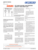
3. Position the Yoke at right angles
to the Gun with the Cam lever to
the front (see picture). Make sure
the vent hole in the lid is
positioned under the Yoke and
the hole in the diaphragm is 180°
to the Lid vent hole.
E
E
Operation
1. Mix coating material to
manufacturers instructions.
2. Fill the cup with the required
amount of material. Fill to no more
than 25mm(1“) from the top of the
cup. DO NOT OVERFILL.
3. Attach Cup to the Lid assembly.
4. Turn needle adjusting screw (10)
on the spraygun clockwise to
prevent movement.
5. Turn pattern valve (5) counter-
clockwise to fully open
6. Adjust inlet air pressure to give 2
bar (29psi) at the gun inlet with
the gun triggered. (pressure
gauge attachment shown under
Accessories is recommended for
this).
7. Turn needle adjusting screw
counter clockwise until first thread
shows.
8. Test spray. If the finish is too dry
reduce airflow by reducing inlet
pressure. If finish is too wet
reduce fluid flow by turning needle
screw (10) clockwise. If
atomisation is too coarse,
increase inlet air pressure. If too
fine reduce inlet pressure.
9. The pattern size can be reduced
by turning adjusting valve (5)
clockwise.
10. Hold gun perpendicular to surface
being sprayed. Arcing or tilting
may result in uneven coating.
11. The recommended spray distance
is 150-200 mm (6”-8”).
12. Spray edges first. Overlap each
stroke a minimum of 50%. Move
gun at a constant speed.
13. Always turn off air supply and
relieve pressure when gun is not
in use.
Air Flow Valve (15)
1. If the airflow valve (15) is fitted
this can be used to reduce the
inlet pressure through the gun.
Screw the Adjusting Knob in to
reduce pressure.

7 © 2007 ITW Finishing Systems and Products
Accessories
Spanner – order SPN-5
Cleaning Brush – order 4900-5-1-K3
Service Kit – order GTi-416 add nozzle size as required (i.e. GTi-416-14)
Pressure gauge Attachment – order GA-515
Gun Mounted Regulator – order DVR-501
Lubricant - order GL-1-K10
Replacement of Parts
1. Turn off air and coating supply
and relieve pressure in the
supply lines, or if using QD
system, disconnect from airline.
2. Release Cup and raise the tube
out of the material. Trigger the
Gun and allow material to drain
back into the cup.
3. Dispose of the surplus material
and clean the cup. Do not use
sharp metalic tools to clean the
cup they will damage the PTFE/
anodising surface.
4. Remove air cap (1) and clean. If
any of the holes in the cap are
blocked with coating material use
a toothpick to clean. Never use
metal wire which could damage
the cap and produce distorted
spray patterns
5. Ensure the tip of the nozzle (2) is
clean and free from damage.
Build up of dried paint can distort
the spray pattern.
6. Lubrication – stud/screw (6),
needle (7) and air valve (11)
should be oiled each day.
Preventative Maintenance
Nozzle (2) and Needle (7) –
Remove parts in the following order:
10, 8, 7, 1 and 2. Replace any worn
or damaged parts and re-assemble
in reverse order. Recommended
tightening torque for nozzle (2) 17-
20 Nm (150-180 lbf in)
Packing – Remove parts 10, 8, 7.
Unscrew cartridge (4). Fit new
cartridge finger tight. Re-assemble
parts 7, 8, and 10 and tighten
cartridge (4) with spanner sufficient
to seal but to allow free movement
of needle. Lubricate with gun oil.
Air valve (11) – Remove Trigger,
parts 6 and 12. Unscrew valve
assembly. Re-assemble, fitting
spring to valve head before fitting
valve.
Spreader valve (5) – Caution:
always ensure that the valve is in
the fully open position by turning
screw fully counter-clockwise before
fitting to body.
Air cap / Nozzle Selection
Refer to coating material
manufacturers recommendations or
ITW Finishing UK Website:
www.itweuropeanfinishing.com
E
E
/