
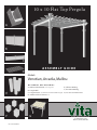
10 x 10 Flat Top Pergola
ASSEMBLY GUIDE
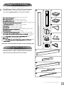
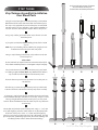
OPTIONAL ACCESSORIES
E) Tall Base Molding
F) Short Base Molding
G) 10 x 10 Canvas Weave Kit
A) Bolt Down Bracket Kit (4 for Pergola)
B) Pergola Wall
C) Pergola Planter - (available for Venetian & Malibu Pergola)
D) Additional Shade Slats Kit (12)
Ver 9.4 10142020
Models:
Venetian, Arcadia, Malibu
www.wearevita.com
C
A
B
D
E
F
G
211 Campbell St Sarnia,
Ontario, Canada, N7T 2G6

Table of Conte nt s
2
10 x 10 Flat Top Pergola
3
10 x 10 Flat Top Pergola
Introduction & Overview……………………………. . . . . . . . . . . . . . . . . . . . . . . . . . . . . . . . . . . . . . . . . . . . . . . .………. . . . . .
Pergola Materials Overview………………………. . . . . . . . . . . . . . . . . . . . . . . . . . . …. . . . . . . . . . . . . . . . . . . . . . . . . . . . . . . . . . .
Pergola Materials Breakdown………………………. . . . . . . . . . . . . . . . . . . . . . . . . . . . . . . . . . . . .…. . . . . . . . . . . . . . . . . . . . . . .
Pergola Additional Materials List………………………………. . . . . . . . . . . . . . . . . . . . . . . . . . . . . . . . . . . . . . . . . . . . . . . . . .
Wood Post Layout & Installation for In-Ground Application………………………………. . . . . . . . . . . . . . . . . . . . .
Wood Post Layout & Installation using Bolt Down Post Brackets for Concrete or Wood Surface……………
Vinyl Column Assembly and Installation Over Wood Posts………………………. . . . . . . . . . ………………….
Main Support Beam Assembly…………………………. . . . . . . . . . . . . . . . . . . . . . . . . . . . . . . . . . . . . . . . . . . . . . . . . . . . . . . . . .
Rafter Assembly………………………………………………. . . . . . . . . . . . . . . . . . . . . . . . . . . . . . . . . . . . . . . . . . . . . . . . . . . . . .
Main Support Beams & Rafter Placement……………………………………. . . . . . . . . . . . . . . . . . . . . . . . . . . . . . . . . . . .
Fastening Main Support Beams, Rafters & Caps …………………………. . . . . . . . . . . . . . . . . . . . . . . . . . . . . . . . . . . . . . .
Shade Slats Installation………………………………………………. . . . . .………….……. .…………. . . . . . ….
PAGE
4
5
6
7
8
9
10
11
12
13
14

Int ro duc tion & O ve r view
3
10 x 10 Flat Top Pergola
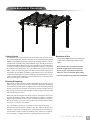
Getting Started
First off, allow us to say thank you for the investment you have made in one
of our fine pergola kits. This kit is designed to be assembled and installed
ideally by two people with basic carpentry knowledge and tools. Do not
attempt alone, especially during the installation stage. Should you decide to
moderately modify the dimensions of your pergola from the standard kit size,
a circular saw with a sharp fine-tooth blade is all that is needed to cut, shorten
or modify the vinyl components. The steel stiffeners for the main beams and
rafters can be cut down using either a hacksaw or a motorized cutting device
designed to cut steel. When assembling components place on a non-abrasive
surface (ie: shipping box) to avoid scratching. We recommend a 15’x15’
area for unobstructed assembling. You should not need to use excessive force
when
assembling any components.
Planning & Preparing
Because this project is made to stand independent of your home, you can
either locate it near your house or let it stand alone in the garden. By keeping
it unattached from your home you will not have to deal with moving existing
gutters or matching eave heights. If you plan to build your pergola close to
the house, please keep the outer extremities of the pergola a minimum of 4
inches back from your eaves.
What looks like the toughest part of this project is actually the easiest, the
graceful, solid-looking columns. We’ve designed these columns to simply be
slipped over treated 4x4 wood posts that are either embedded in concrete or
directly mounted to a concrete or wood surface using our bolt down brackets.
See pages 7, 8 and 9 for more details.
It is critical before you start, to consider the current slope of elevation
where the pergola is planned - if there is any. Also utility or sprinkler line
location is important to identify prior to excavating holes if necessary.
You should also check to verify
local building codes, ordinances, neighbour-
hood covenants, or height restrictions regarding this type of structure.
Restriction of Use
This product is not designed to carry additional
weight loads such as swings, people or other
objects.
Please take the time to read this instruction
guide thoroughly prior to the construction
of your pergola. If you have any questions,
feel free to contact our technical dept by calling
1 800 282 9346 (Mon to Fri 8:00 A.M to 5:00 P.M.
EST).
(Venetian Pergola Shown)

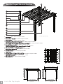
Venetian Pergola Materials Overview
4
10 x10 Flat Top Pergola
6
1
2
4
3
9
(Venetian Pergola Shown)
1. Post Caps (4) White #10699-1 Composite #14030
2. Main Column Tops (4) White #10722-1 Composite #14037
3. Post Trims (8) White #10698-1 Composite #14029
4.
Rafter
& Beam Decorative End Caps
(16) White #10700-1 Composite #14012
5. Main Support Beams with pre-drilled holes on one side(4) White #10716-1 Composite #14038
6. Beam & Rafter Joiners (8) White #10707-1 Composite #14049
7. Long Steel Stiffeners for Main Support Beams & Rafters(8) #10996
8. Short Steel Stiffener for Main Beams (4) #10995
9. Main Column Bottoms (4) White #10690-1 Composite #14036
10.
Rafter Brackets
(8) White #10536 Composite #14050
11. Rafters (12) White #10713-1 Composite #14039
12
Top View
5
7
11
10
Front View
Side View
8
13
12.
One Way 4”x4” Internal Wood Post Guide
(4) White #10696-1 Composite #14027
13.
Shade Slat Joiners
(12) White #10600-1 Composite #14028
14.
Shade Slats (24)
White #10717-1 Composite #14040
14
110 in [279 cm] 110 in [279 cm]
107 1/2 in [273 cm]
92 in [234 cm]
96 5/8 in [245 cm]
144 1/4 in [366 cm]
144 1/4 in [366 cm]

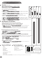
Check Boxes (
T
otal of
5) for These
Co
n
t
e
nts
In the event of missing or defective parts please call our customer
service
dept. at
1 800 282 9346
(Mon. to F
ri. 8:00 AM to 5:00 PM EST).
1. Main Column Bottoms (4) White #10690-1 Composite #14036
2. Main Column Tops (4) White #10722-1 Composite #14037
3. Beam & Rafter Joiners (8) White #10707-1 Composite #14049
4.
One Way 4”x4” Internal Wood Post Guide
(4) White #10696-1 Composite #14027
5. *Shade Slat Joiners (12) White #10600-1 Composite #14028
6. Post Caps (4) White #10699-1 Composite #14030
7. Post Trims (8) White #10698-1 Composite #14029
8.
Rafter & Beam Decorative End Caps
(16) White #10700-1 Composite #14012
9.
Rafter Brackets
(8) White #10536 Composite #14050
10. *Shade Slat Decorative End Caps (24) White #30030-1 Composite #14032
11. Main Support Beams (With Pre-Drilled Holes One Side) (4) White #10716-1
12. Short Steel Stiffener Inserts for Main Support Beams (4) #10995
13. Rafters (12) White #10713-1 Composite #14039
14. Long Steel Stiffener Inserts for Main Support Beams & Rafters (8) #10996
15.
*Shade
Slats
(24) White #10717-1 Composite #14040
Pergola Materials Breakdown
1
Not to Scale
5
10 x 10 Flat Top Pergola
(Pergola Accessories Not included)
Beam Insert
Beam / Rafter Insert
A
A
11
12
13
14
*15
2
6
7
3
8
4
9
*5
*10
Malibu Pergola Materials Breakdown
(Includes boxes 1-4 plus a 5th box with canvas kit)
*Refer to instructions within box 5 for a list of parts.
Composite #14038
* these parts are included with the Venetian and Arcadia Pergolas only

Pergola Additional Materials List
Hardware (in plastic bag)
NOTE: WE HAVE INCLUDED 10% EXTRA SCREWS
BEYOND WHAT IS IDENTIFIED BELOW.
All Screws Included with this Kit are Self-Auguring.
A. Vinyl Weld Glue (3) White #20000 Composite #20029
B.
2 1/2” (64 mm) Self-Auguring Stainless Steel Screws (16)
White #20009-1 Composite #20032
(to lock vinyl column and wood post together at bottom of each post
)
C.
2 1/2” (64 mm) Self-Auguring Stainless Steel Screws (16)
White #20009-1 Composite #20032
(to lock vinyl column and wood post together at top of each post just above trim cap
)
D.
4” (102 mm) Self-Auguring Stainless Steel Screws (64)
White #20006 Composite #20034
(to lock the intersection of beams and first rafters with vinyl columns)
E.
1 1/2” (38 mm) Self-Auguring Stainless Steel Screws (48)
White #20005 Composite #20031
(joiner screws)
F. 5/8” (16 mm)
Self-Auguring Stainless Steel Screws (32)
White #20016 Composite #20030
(for rafter brackets)
G.
*2 1/2” (64 mm) Self-Auguring Stainless Steel Screws (72)
White #20009-1 Composite #20032
(for shade
slats only, not required for the Malibu Pergola)
Extra Materials You will Need
(Purchase separately from www.wearevita.com or retailer of our products)
If Mounting Pergola on Concrete or Wood Deck (Not intended to be
installed on concrete pavers, patio stones, or interlocking bricks)
H.
4x4x7' (10cm x 10cm x 213 cm) Pressure-Treated Wood Posts (4)
(purchase at local building center)
I. 4x4 Bolt Down Bracket Kit
(purchase from Vita or a retailer of our products)
Refer to bolt down
bracket instructions for hardware requirements, as they pertain to your application:
If mounting pergola onto an existing concrete surface:
• 1/2“
x
3
1/2” x
12“
(1.3
cm
x
8.9
cm
x
30
cm) Wood
Shims
(32) - Can Be Cut from 1/2” (1.3 cm) Sheet of Plywood
• 1/4” x 2 3/4” (6 mm x 70 mm) Cement Screws (12)
• 3/16” (4.7 mm) Concrete Drill bit. Minimum 3” (76 mm) long (1)
If mounting pergola onto a wooden/composite deck with AN ACCESSIBLE UNDERSIDE:
• 1/2“ x 3 1/2” x 12“ (1.3 cm x 8.9 cm x 30 cm) Wood Shims (32) - Can Be Cut from 1/2”(1.3 cm) Sheet of Plywood
• 1/4” (6 mm) x ?“ Bolts and Nuts - Countersunk Head (12) Length depends on thickness of blocking material)
• 1/4” (6 mm) Washers (12)
• 1/4” (6 mm) Wood drill bit. Minimum 3“ (76 mm) Long (1)
If Mounting Pergola in Ground
J.
4x4x10' (10cm x 10cm x 305 cm)Pressure-Treated Wood Posts (4)
(purchase at local building center)
K.
Concrete Ready Mix (4) (purchase at local building center)
Tools You Will Need
• Level
• Hammer
• Tape Measure
• String Line
• Wood Stakes (4)
(temporary support for string line)
• Step Ladders (2)
• Cordless Drill
• 1/8” x 2” (3 mm x 51 mm) Drill Bit (1)
(to pre-drill holes on
bottom of joiner to penetrate steel inserts as necessary)
K
CONCRETE - Ready Mix
Not to Scale
6
Purchase Separately
*G
A
B
D
F
C
E
Purchase Separately
I
Tools You May Need
• Circular Saw with Fine Tooth Blade
• Framing Level
• Framing Square
• Hacksaw
(or a motorized cutting
device designed to cut steel)
Purchase Separately
H
Purchase Separately
J

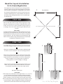
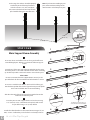
Wood Post Layout & Installation
for In-Ground Application
Measure and mark out the location of the pergola posts using
string line and temporary wood stakes. Diagonal distances must
be the same to ensure a square installation. Adjust string lines
accordingly. The inside corner of the string lines will be the post
location.
Please Note:
Should you decide to moderately modify the dimensions of your
pergola from the standard kit size, a circular saw with a sharp
fine-tooth blade is all that you need to cut, shorten or modify the
vinyl components. The steel stiffeners for the main beams and
rafters can be cut down using either a hacksaw or a motorized
cutting device
designed to cut steel.
1
This pergola can also be installed on a pre-existing wood or
concrete surface using our bolt down bracket system with
a 4x4 wood post (sold separate). See page eight for more details.
Post location and placement is the most critical step in the
overall installation process. Please double check for the
possibility of any underground utilities such as sprinkler, gas
or telephone lines.
STEP ONE
After you have determined where the posts will be located,
excavate 10” (25 cm ) diameter x 36” (91 cm) deep post holes.
After holes are dug and cleaned, place the 4x4 wood post into
a hole ensuring it’s level and square to string lines. The final post
height should be no more than 84” (213 cm) out of the ground.
If a post is higher because of obstructed excavation of
footings, please cut down in height accordingly.
Fill the vacant hole with pre-mixed concrete all the way to
within 3” (8 cm) of the top of the hole. After the concrete has
set, back fill & compact the 3” (8 cm) space with soil/sod.
Repeat for all four posts.
Please Note:
Some 4x4 pressure treated posts can be larger than 3 1/2 x 3 1/2 (9 cm
x 9 cm)
square due to twisting or cracking. We have allowed a
tolerance
for this in the internal one way and two way 4x4 wood post
guides
(see page 8). However in extreme cases you may need to shave
down
the top of the 4x4
wood post slightly to get the vinyl post started
over the wood post. Before installing your wood posts in the ground,
please check to confirm this and correct at this stage if necessary.
1
2
3
STEP T WO
Install Wood Supporting Posts Directly into the Ground
4
111 1/2"
(283.2 cm)
111
1/2"
(283.2 cm)
10”
(25 cm)
36” (91 cm)
84” (213 cm)
1
2
3”
(8 cm)
3
7
10 x 10 Flat Top Pergola
Overhead View
157 11/16 from corner of wood post to corner of wood post.

Measure and
mark out the location of the bolt down brackets
using string or chalk line. Measure from the edges of the base
plates (not the vertical side walls). Diagonal distances must be
the same to ensure a square installation. Adjust string lines
accordingl y. The inside corner of the string lines will be the corner
of the bottom flange.
Mark out the location of bolt down brackets accordingly using
the base of the bracket accordingly.
Using a 3/16” (4.7 mm) mason
ry drill bit, drill 3“ (8 cm) deep holes
to allow installation of 2 3/4” (70 mm) conc rete screws (Not included)
1
1
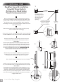
OPTIONAL STEP
Woo
d Post Layout & Installation
Using Bolt Down Brackets
for Concrete or Wood Surface
Note: for additional information on the bolt down bracket
installation, refer to the bolt down bracket instructions.
2
3
3
With the four post brackets
installed plumb, proceed to set
the 4 x4 x7’(213 cm) wood post in place. Use wood screws to
s ecure the
posts to the bracket.
Repeat for all 4 posts.
Posts should be approximately 84” (213 cm) in height.
5
6
3“ ( 8 cm) Deep
4
4
8
10 x 10 Flat Top Pergola
Proceed to install th
ree 2 3/4” (70 mm) concrete screws into
the bottom
base of the bolt down bracket. (Not included)
Please Note:
Concrete patios generally have sloped surface for water run-off.
If this is the case, when you secure the bolt down brac
ket to the
concrete, the bracket may be at an angle. This can be corrected
for level using ga lvaniz
ed steel washers (not provided), acting
as shims underneat h the base to level - VERY IMPORTANT OR
PERGOLA BEAMS
AND
RAFTERS WILL NOT BE LEVEL.
2
Marker
* Orientate brackets
accordingly to reduce
offset motion of posts.
(direction of arrows
denote flange
opening)
*
*
*
*
110 3/8 in
280.4 cm
110 3/8 in
280.4 cm
156 1/8 in (396.5 cm)
From corner of bracket
(Bottom of flange)
to corner of bracket
Attach 8 post shims to each of the wooden post, placing shims
6”
(15 cm) on all four sides, near the bottom & top 72” (183 cm).
Please Note:
Some 4x4 pressure treated wood posts can be larger than 3 1/2 x
3
1/2 (9 cm x 9 cm) square due to twisting or cracking. We have
allowed a
tolerance for this in the post brackets and the internal
one way and
two way 4x4 wood post guides. However in extreme
cases, you
may need to shave down the end of your 4x4 wood post
slightly
to allow access.
7
84” (213 cm)
5
6
Level
7
1/2”x3 1/2”x12”
shims on all
four sides
near bottom
and the top
6 in
(15 cm)
72 in (183 cm)
Not to Scale

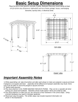
Vinyl Column Assembly & Installation
Over Wood Posts
9
10 X 10 Flat Top Pergola
1
Using the vinyl weld glue, insert the One Way 4”x4” Internal
Wood Post Guide in the one end of the main column posts.
This step is only applicable if your wood 4x4 post are embedded
into the ground. If your pergola is going to be installed on
wood or concrete surface, please dispose of these four pieces.
Using a step ladder, guide the bottom vinyl columns over the
wood 4x4 posts
.
If you purchased Short or Tall Base Moldings, slide the base mold
on post.
Note: If you are installing a Privacy Wall on the pergola, do not
install base mold on the posts with side panel.
Using a step ladder guide the top vinyl columns over the
wood 4x4 posts.
Please Note:
Ensure that holes at top of column are orientated correctly for
future beam and rafter placement. See diagram at top of next page.
Connect the bottom and top vinyl column by using vinyl weld
and sliding together.
Please Note: Vinyl Weld Glue has about a
sixty second cure time and about a
20 minute dry time.
Slide the bottom post trim into position to cover the joint on
the column.
Slide the top post trim into approximate position just below the
bottom routed hole on the bottom of the top vinyl column assembly.
If necessary, adjust post heights accordingly to ensure future
level installation of beams and rafters as necessary. If slope is severe
causing a height difference between the posts, you may need
to trim down the bottom of two or more of your vinyl columns
as necessary.
Secure the vinyl columns to the wood posts using 4 – 2 1/2“ (64
mm)
self-auguring stainless steel screws at 8” (20 cm)up from
the base
of the posts, and 4 – 2 1/2” (64 mm)self-auguring
stainless steel screws
just above the trim cap as illustrated. This will
prevent possible uplift durin
g high winds,
etc. If base moldings are
installed, position screws above the base moldings.
1
2
4
STEP THREE
5
6
7
8
9
2 4 5
6 7
8
Slope?
*Ensure that holes at top of column
are orientated correctly for
future beam and rafter placement.
*
9
8“
3
3
or

110"
(279.4 cm)
110"
(279.4 cm)
Beam Insert
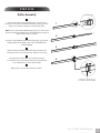
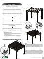
Main Support Beam Assembly
1
Insert two short steel stiffener into one long steel stiffener to
create full length piece. Repeat so you have two full main support
Insert the end of the main support beam marked ‘A’ into the joiner.
Install the joiners so that the side with the four holes are facing
up. Push
firmly until the extrusion bottoms out inside the joiner.
Please Note:
Be sure to orientate the main support beams correctly so the
pre-drilled holes for future installation of rafter brackets is correct.
Insert one assembled steel stiffener (with steel block facing up),
into the lower pocket of the main support beam past the joiner.
Push until steel block hits the internal ribbing
.
Slide the other end of the main support beam marked ‘A’ over the
steel insert and into the joiner.
Screw the joiner to main support beams and steel insert using
1 1/2” (38 mm) screws. The bottom and top holes will need to
be pre-
drilled using a 1/8" (3 mm) drill bit.
Install the rafter brackets to the main beams using 5/8” (16
mm) screws. Follow the
pre-drilled holes to identify locations.
1
2
3
beams.
STEP FOUR
4
5
2
10
10 x 10 Flat Top Pergola
3
5
6
6
Four holes facing up
4
Pre-drill holes on bottom and top to
accomodate for internal steel stiffener.
At this stage, the columns should be properly
installed as per the following illustration,
with the columns 110” (279.4 cm) apart.
Also, notice that the holes at the top of each
post should be facing the same direction.
Beam Insert
Beam Insert
Beam Insert
Beam Insert
Beam Insert
Bea
Steel block should face up
A
A
A
Note: If you have base molding on your
posts, measure above moldings as the
measurement is to be from post to post.

Four holes facing up
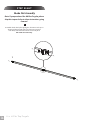
Rafter Assembly
Insert the end of the rafter marked ‘A’ into a joiner. Install
the joiners so that the side with the four holes is facing up.
Push
firmly so the extrusion bottoms out inside the joiner.
Note: If you purchased the Malibu Pergola, please use the plain
joiners included in the Malibu box. This will allow the canopy to
glide over the rafters smoothly.
Insert one steel stiffener (with steel block facing up), into the
lower pocket of the rafter. Push until steel block hits
internal ribbing.
Slide the other end of rafter marked ‘A’ over the steel insert and
into the joiner to create one full rafter. Repeat as necessary.
Screw the joiner to the rafters and steel inserts using 1
1/2” (38 mm) screws. The bottom and top holes will need to
be pre-drilled
using a 1/8" (3 mm) drill bit.
Repeat steps 1 to 4 for the remaining 5 rafters.
1
2
3
STEP FIVE
4
11
10 x 10 Flat Top Pergola
1
2
4
3
Pre-drill holes on bottom and top to
accomodate for internal steel stiffener
Rafter Insert
A
A
A
4
5

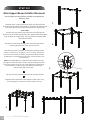
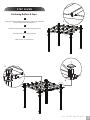
Main Support Beams & Rafter Placement
12
10 x 10 Flat Top Pergola
1
Using a helper and two ladders proceed to complete the
following steps:
Slide the main support beam with rafter clips through both
holes of the vinyl column (overshooting), and then back through
both
holes of the opposite column. Repeat for oppos
ite main support beam.
Please Note:
The top of the vinyl columns may need to be tensioned in opposite
directions to each other to allow the main support beams and rafters
to be installed on a slight angle. The vinyl columns naturally allow
some measure of flex.
Slide the two outer rafters through both holes of the vinyl column
and through both holes of the opposite column.
Final adjust the beams and rafters ensuring the overhang past the
columns is equal to the eye (roughly 4" or 10 cm overhang). Using 4” (102
mm) screws lock the beams and rafters
into position inside the columns
by driving in 8 screws from the outside
and 8 screws from the inside
of each column.
Note: For the Main Beams, pre-drill the lowest bottom holes (two
through the outside face of the column, and two through the inside
face of the column) using the 1/8" (3 mm) drill bit to accom
modate
for installation of screws into the steel stiffeners located in the
lower pocket of the main beams.
Place the remaining rafters in the front and rear rafter brackets.
Complete a final adjustment of the remaining rafters. All spacing
and overhangs past columns should be equal to the eye.
1
2
3
STEP SIX
4
2
4
5
3
4 in
(10 cm)
Overhang

Fastening Rafters & Caps
13
10 x 10 Flat Top Pergola
1
Using 5/8” (16 mm) self-auguring stainless steel screws attach the
pergola
rafters to the rafter brackets.
Install decorative pergola end caps using vinyl weld.
Install the post caps using vinyl weld.
Final position your post trims.
1
2
3
STEP SEVEN
4
3
4

14
STEP EIGHT
10 x 10 Flat Top Pergola
Assemble shade slats by first gluing the decorative end caps as
shown, and then inserting the two slats into one joiner.
Push firmly until extrusion bottoms out inside joiner.
No screws
are necessa
ry.
Shade Slat Assembly
1
1
Note: If you purchased the Malibu Pergola, please
skip this step and refer to those instructions going
forward.

15
10 x 10 Flat Top Pergola
STEP EIGHT
2
3
4
8
3/8
”
Install first shade slat adjacent to the top of the vinyl columns.
Install the rest of the sh
ade slats at the 8 3/8” (21.25 cm) spacing.
Note: if you purchased and additional shade slat kit (24 shade slats
total, install the rest of the shade slats at a 3 1/4” (8.25 cm) spacing).
See image 3a below.
2
3
4
Install one 2 1/2” (64 mm) screw at each intersection of rafter and
shade slat.
Suggestions for Additional Shade as Necessary
Available Shade Accessories:
• Additional Shade Kit - Provides an additional 12 shade slats
a total of 24 shade slats
• 10 x 10 Canvas Weave Kit - Provides 5 canvas weave strips
(Can only be installed with the standard 12 shade slats
provided with the pergola)
Shade Slats Installation
3a - Pergola with Additional Shade Slat Kit
3 1/4”
(8.25 cm)
Spacing
If you purchased the Canvas Weave Kit, please follow the
spacing requirements for installing 12 shade slats only.
The 1 1/2 x 1 1/2 (4 cm 4 cm) shade slats are designed to be
installed with
8 3/8” (21.25 cm)spacing between each slat.
Shade slats are designed to extend approximately 8 1/4” (21
cm) past
the last rafter. Measurement includes the pre-installed
pergola
ends. Your goal is to ensure that all the shade slats
overhang
equally to the eye.
Note:
If the additional shade slat kit is being installed retroactively,
simply place one shade slat assembly in between two existing
shade slats. Only 11 additional shade slats will be used in this
case.
If you prefer to install all 12 of the additional shade slats,
temporarily unfasten 10 of the existing shade slats. The 2
existing shade slats fastened against the colums can remain
fastened. Follow the instructions detailed in Step 3 to install the
remaining shade slats. To prevent moisture from entering the
rafters, we recommend using small amount of bright white
silicon sealant (purchased separately) to seal any exposed screw
holes.
www.wearevita.com
-
 1
1
-
 2
2
-
 3
3
-
 4
4
-
 5
5
-
 6
6
-
 7
7
-
 8
8
-
 9
9
-
 10
10
-
 11
11
-
 12
12
-
 13
13
-
 14
14
-
 15
15


Vita 10x10 Malibu Canopy Pergola Installation guide
- Type
- Installation guide
- This manual is also suitable for
Ask a question and I''ll find the answer in the document
Finding information in a document is now easier with AI
Related papers
-
Vita VA42022 Installation guide
-
-
-
-
-
-
-
-
-
Other documents
-
New England Arbors VA42022 User guide
-
Severe Weather 11630 User manual
-
-
-
-
 Backyard Discovery 1505513com Installation guide
-
-
 Backyard Discovery 6214com Installation guide
-
-

