Page is loading ...

Owner’s Manual
Read and save these
instructions.
For help please visit
yourhome.honeywell.com
RLV210A
Line Voltage
Electric
Baseboard Heat
Thermostat
Application
This thermostat is designed to control an electric heating system such as a baseboard
heater, a convector or a fan-forced heater.
The thermostat CANNOT be used with:
• a resistive load under 1.25 A
• a resistive load over 12.5 A (120/208/240V)
• a system driven by a contactor or a relay (inductive load)
• a central heating system
Supplied Parts
• One (1) thermostat
• Two (2) screws
• Two (2) solderless connectors for copper wires
CAUTION Fire Hazard.
Special CO/ALR solderless connectors must be used if the thermostat will be
connected to aluminum wires.

2
ATTENTION: MERCURY RECYCLING NOTICE
This product does not contain mercury. However,
this product may replace a product that contains
mercury. Mercury and products containing
mercury should not be discarded in household
trash.
For more information on how and where to
properly recycle a thermostat containing
mercury in the United States, please refer to the
Thermostat Recycling Corporation at
www.thermostat-recycle.org.
For mercury thermostat recycling in Canada,
please refer to Switch the Stat at
www.switchthestat.ca
NO MERCURY
Hg
Specifications
Temperature Setting Range: 5°C to 27°C (41°F to 80°F)
Operating Temperature: 0°C to 50°C (32°F to 120°F) non-condensing
Storage Temperature: -20°C to 50°C (-4°F to 120°F)
Supply: 120 VAC, 50/60Hz; 208 VAC, 50/60Hz; 240 VAC, 50/60Hz
Minimum Load: 1.25 A (150 W); 1.25 A (300 W)
Maximum Load: 12.5 A (1500 W); 12.5 A (3000 W)
Installation
WARNING Electrical Shock Hazard.
This thermostat is a line voltage control (120–240 Volts). Do not install it if
you are not completely familiar with house wiring. If handled improperly,
there is risk of electric shock hazard, which may cause serious injury or
death.
1. Connect the thermostat as shown on page 3.
2. Remove the thermostat faceplate cover by prying it from the top or bottom
with your fingers.
3. Install the thermostat onto the electrical box using supplied screws.
4. Place the faceplate cover back.
5. Apply power to the heating system.

3
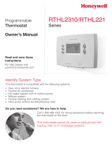
TWO-WIRE INSTALLATION
FOUR-WIRE INSTALLATION
M35696
Fig. 1 Thermostat wiring diagram.
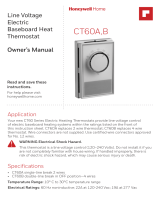
FACEPLATE COVER ON
M35694
TEMPERATURE SETTING KNO
B
Fig. 2 Faceplate cover on.
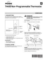
FACEPLATE COVER OFF
MOUNTING SCREW OPENINGS
M35695
Fig. 3 Faceplate cover off.

Automation and Control Solutions
Honeywell International Inc.
1985 Douglas Drive North
Golden Valley, MN 55422
yourhome.honeywell.com
® U.S. Registered Trademark.
© 2015 Honeywell International Inc.
33-00148EFS—01 M.S. 10-15
Printed in U.S.A.
33-00148EFS-01
1-year limited warranty
Honeywell warrants this product, excluding battery, to be free from defects in the workmanship or materials, under
normal use and service, for a period of one (1) year from the date of purchase by the consumer. If at any time during
the warranty period the product is determined to be defective or malfunctions, Honeywell shall repair or replace it (at
Honeywell’s option).
If the product is defective,
(i) return it, with a bill of sale or other dated proof of purchase, to the place from which you purchased it; or
(ii) call Honeywell Customer Care at 1-800-468-1502. Customer Care will make the determination whether the product
should be returned to the following address: Honeywell Return Goods, Dock 4 MN10-3860, 1885 Douglas Dr. N.,
Golden Valley, MN 55422, or whether a replacement product can be sent to you.
This warranty does not cover removal or reinstallation costs. This warranty shall not apply if it is shown by Honeywell
that the defect or malfunction was caused by damage which occurred while the product was in the possession of a
consumer.
Honeywell’s sole responsibility shall be to repair or replace the product within the terms stated above. HONEYWELL
SHALL NOT BE LIABLE FOR ANY LOSS OR DAMAGE OF ANY KIND, INCLUDING ANY INCIDENTAL OR
CONSEQUENTIAL DAMAGES RESULTING, DIRECTLY OR INDIRECTLY, FROM ANY BREACH OF ANY WARRANTY,
EXPRESS OR IMPLIED, OR ANY OTHER FAILURE OF THIS PRODUCT. Some states do not allow the exclusion or
limitation of incidental or consequential damages, so this limitation may not apply to you.
THIS WARRANTY IS THE ONLY EXPRESS WARRANTY HONEYWELL MAKES ON THIS PRODUCT. THE DURATION
OF ANY IMPLIED WARRANTIES, INCLUDING THE WARRANTIES OF MERCHANTABILITY AND FITNESS FOR A
PARTICULAR PURPOSE, IS HEREBY LIMITED TO THE ONE-YEAR DURATION OF THIS WARRANTY.
Some states do not allow limitations on how long an implied warranty lasts, so the above limitation may not apply to
you. This warranty gives you specific legal rights, and you may have other rights which vary from state to state.
If you have any questions concerning this warranty, please write Honeywell Customer Relations, 1985 Douglas Dr,
Golden Valley, MN 55422 or call 1-800-468-1502.
The product is certified by CSA under the following standards:
• CAN/CSA-C22.2 No. 24 Temperature-Indicating and Regulating Equipment.
• UL 873 Temperature-Indicating and Regulating Equipment.
• CSA C828-06, section 4.3 Performance requirements for thermostats used
with individual room electric space heating devices.

11
INSTALACIÓN DE DOS CABLES
INSTALACIÓN DE CUATRO CABLES
MS35696
Fig. 1 Diagrama de cableado del termostato.
CUBIERTA DE LA PLACA FRONTAL INSTALADA
MS35694
PERILLA PARA CONFIGURACIÓ
N
DE LA TEMPERATURA
Fig. 2 Cubierta de la placa frontal instalada.
CUBIERTA DE LA PLACA
FRONT
AL NO INSTALADA
ABERTURAS PARA LOS
TORNILLOS DE INSTA
LACIÓN
MS35695
Fig. 3 Cubierta de la placa frontal no instalada.
/