Page is loading ...

Through-Feed Conduit:
Note: Some units may not allow this mounting or may require
special high temperature cable. See labels on back plate for
instruction.
Knock-out holes are provided to permit mounting of the back
plate on vertical surfaces with two 3/8'’ bolts (not provided). The
-inch conduit is then positioned in the cradles on each side of back
plate and secured to back plate with clips and screws provided
(see figure 2). The conduit may also be secured to the wall on either
side of the fixture with conduit straps (not provided). Wire the unit
(see Wiring). Knock-out the sections on each side of the front
housing using pliers, twisting inwardly. Re-attach the front
housing/reflector over the back plate. For W25C having socket
mounted in front housing, plug wire assembly must be
re-connected as front housing is installed.
Install lamp (see LAMP INSTALLATION) and re-install refractor
or cut-off optical assembly.
NOTE: Do not overcompress the gasket on acrylic lens units as
this may cause the lens to crack around the screw holes.
B. WIRING
Make all electrical connections in accordance with the National
Electrical Code and any applicable local code requirements.
Verify that supply voltage is correct by comparing it to
nameplate.
Customer wiring enters either through the center hole in the
back plate or through the conduit entrance knock-outs on the sides
of the front housing. In either case, an easy access wiring area
(see figure 2) is provided for electrical connections.
Route incoming supply conductors through clips provided and
maintain half inch minimum spacing from ballast and reflector.
NOTE: Connect ground lead to ground (gnd) screw on the back
plate.
Do not remove insulated connectors from wires not needed for
required voltage connection.
IF SINGLE VOLTAGE:
All single voltage ballasts are pre-wired such that user need
only connect the supply conductors.
IF MULTIVOLT: (120/208/240/277 volts)
Connect the ballast lead with the insulated terminal to the
desired voltage terminal as indicated on the ballast terminal
nameplate.
IF MULTIWATT:
Multiwatt ballasts are available in various combinations of
wattage. See wiring instructions on wiring tag inside the
luminaire.
To complete installation refer to MOUNTING.
LAMP INSTALLATION
35-201578-M3 (11/99)
Use only lamps specified on nameplate. Observe lamp
manufacturer’s recommendations and restrictions on lamp
operation, particularly ballast type, burning position, etc.
Lamp Tightness-Mogul Base Lamp: The lamp should be securely
inserted to the NEMA-EEI specified torque of 35 inch-pounds,
which is best achieved by very firm tightening sufficient to fully
depress and load the center contact of the socket.
Lamp Tightness-Medium Base Lamp: The lamp should be
tightened to a light firmness sufficient to depress the center
contact.
MAINTENANCE AND CLEANING
It will occasionally be necessary to clean the outside of the
refractor to maintain light levels. Frequency of cleaning will
depend on ambient dirt level and minimum light level which is
acceptable to the user. The refractor should be washed in a
solution of warm water and any mild, nonabrasive household
detergent, rinsed with clean water and wiped dry. Should the
optical assembly become dirty on the inside, wipe the reflector
and clean the refractor in the above manner.
The light output of a luminaire is dependent on the age of the
lamp. In applications where the light level is critical, it may be
desirable to replace lamps before they burn out. The lamp
manufacturer can provide data showing how the lamp light output
decreases with use.
GEH-3932C
Wallighter 175 and
Wallighter 250 Cutoff Luminaires
INSTRUCTIONS
READ THOROUGHLY BEFORE INSTALLING
W1LR, W1SR, W1LG, W1SG, W25C (cutoff optics)
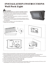
A. MOUNTING
WARNING
Risk of electric shock
• Turn power off before servicing
– see instructions
CAUTION
Unit will fall if not installed properly
• Follow installation instructions
WARNING
Risk of fire
• Use supply wire specified on
nameplate
GENERAL
This luminaire is designed for outdoor lighting applications, and
should not be used in areas of limited ventilation, or in high
ambient temperature enclosures. For optimum performance, it
should be installed and maintained according to the following
recommendations.
UNPACKING
This luminaire has been properly packed so that no parts should
have been damaged during transit. Inspect to confirm.
INSTALLATION
The refractor must be removed to access two bolts (on each
side of the reflector) which secures front housing to back plate.
Removal of the front housing allows access for mounting and
wiring.
NOTE: For units marked W25C having socket mounted in front
housing, plug wire assembly located in center top of back plate
must be unplugged while removing front housing.
A gasket is provided with the unit to be used when mounting
over an outlet box, and should be installed between rear of back
plate and the mounting surface. If additional sealing is desired,
caulk back of housing with generic non-hardening sealant (not
provided) across the top and down both sides.
Outlet Box Mounting: The luminaire can be mounted to a
suitable surface-mounted outlet box (3'’ or 4'’ octagon, or 2'’x4'’
rectangular). The back plate may be attached to the outlet box with
two 10-24 screws (not provided), approximately ‘’ long. An alternate
method of mounting the back plate over a surface-mounted outlet
box is to position back plate over box and mount with two 3/8'’ bolts
(not provided) through the knock-out holes provided in the back
plate (see figure 2). Wire the unit (see Wiring). Reattach the front
housing/reflector over the back plate. For W25C having socket
mounted in front housing, plug wire assembly must be
re-connected as front housing is installed.
Figure 1
Figure 2
CAUTION
Risk of burn
• Allow lamp/fixture to cool before
handling
WARNING
Risk of burn
• Do not touch operating luminaire
These instructions do not purport to cover all details or variations in equipment nor to provide for every possible contingency to be met in connection with installation, operation or
maintenance. Should further information be desired or should particular problems arise which are not covered sufficiently for the purchaser’s purposes, the matter should be referred
to GE Lighting Solutions.
g
GE Lighting Solutions is a subsidiary of the General Electric Company. Evolve and other trademarks belong to GE Lighting Solutions. The GE brand and logo are trademarks of the General Electric Company.
© 2011 GE Lighting Solutions. Information provided is subject to change without notice. All values are design or typical values when measured under laboratory conditions.
GE Lighting Solutions • 1-888-MY-GE-LED • www.gelightingsolutions.com
16943533----888
g
GE
Lighting Solutions

Through-Feed Conduit:
Note: Some units may not allow this mounting or may require
special high temperature cable. See labels on back plate for
instruction.
Knock-out holes are provided to permit mounting of the back
plate on vertical surfaces with two 3/8'’ bolts (not provided). The
-inch conduit is then positioned in the cradles on each side of back
plate and secured to back plate with clips and screws provided
(see figure 2). The conduit may also be secured to the wall on either
side of the fixture with conduit straps (not provided). Wire the unit
(see Wiring). Knock-out the sections on each side of the front
housing using pliers, twisting inwardly. Re-attach the front
housing/reflector over the back plate. For W25C having socket
mounted in front housing, plug wire assembly must be
re-connected as front housing is installed.
Install lamp (see LAMP INSTALLATION) and re-install refractor
or cut-off optical assembly.
NOTE: Do not overcompress the gasket on acrylic lens units as
this may cause the lens to crack around the screw holes.
B. WIRING
Make all electrical connections in accordance with the National
Electrical Code and any applicable local code requirements.
Verify that supply voltage is correct by comparing it to
nameplate.
Customer wiring enters either through the center hole in the
back plate or through the conduit entrance knock-outs on the sides
of the front housing. In either case, an easy access wiring area
(see figure 2) is provided for electrical connections.
Route incoming supply conductors through clips provided and
maintain half inch minimum spacing from ballast and reflector.
NOTE: Connect ground lead to ground (gnd) screw on the back
plate.
Do not remove insulated connectors from wires not needed for
required voltage connection.
IF SINGLE VOLTAGE:
All single voltage ballasts are pre-wired such that user need
only connect the supply conductors.
IF MULTIVOLT: (120/208/240/277 volts)
Connect the ballast lead with the insulated terminal to the
desired voltage terminal as indicated on the ballast terminal
nameplate.
IF MULTIWATT:
Multiwatt ballasts are available in various combinations of
wattage. See wiring instructions on wiring tag inside the
luminaire.
To complete installation refer to MOUNTING.
LAMP INSTALLATION
35-201578-M3 (11/99)
Use only lamps specified on nameplate. Observe lamp
manufacturer’s recommendations and restrictions on lamp
operation, particularly ballast type, burning position, etc.
Lamp Tightness-Mogul Base Lamp: The lamp should be securely
inserted to the NEMA-EEI specified torque of 35 inch-pounds,
which is best achieved by very firm tightening sufficient to fully
depress and load the center contact of the socket.
Lamp Tightness-Medium Base Lamp: The lamp should be
tightened to a light firmness sufficient to depress the center
contact.
MAINTENANCE AND CLEANING
It will occasionally be necessary to clean the outside of the
refractor to maintain light levels. Frequency of cleaning will
depend on ambient dirt level and minimum light level which is
acceptable to the user. The refractor should be washed in a
solution of warm water and any mild, nonabrasive household
detergent, rinsed with clean water and wiped dry. Should the
optical assembly become dirty on the inside, wipe the reflector
and clean the refractor in the above manner.
The light output of a luminaire is dependent on the age of the
lamp. In applications where the light level is critical, it may be
desirable to replace lamps before they burn out. The lamp
manufacturer can provide data showing how the lamp light output
decreases with use.
GEH-3932C
Wallighter 175 and
Wallighter 250 Cutoff Luminaires
INSTRUCTIONS
READ THOROUGHLY BEFORE INSTALLING
W1LR, W1SR, W1LG, W1SG, W25C (cutoff optics)
A. MOUNTING
WARNING
Risk of electric shock
• Turn power off before servicing
– see instructions
CAUTION
Unit will fall if not installed properly
• Follow installation instructions
WARNING
Risk of fire
• Use supply wire specified on
nameplate
GENERAL
This luminaire is designed for outdoor lighting applications, and
should not be used in areas of limited ventilation, or in high
ambient temperature enclosures. For optimum performance, it
should be installed and maintained according to the following
recommendations.
UNPACKING
This luminaire has been properly packed so that no parts should
have been damaged during transit. Inspect to confirm.
INSTALLATION
The refractor must be removed to access two bolts (on each
side of the reflector) which secures front housing to back plate.
Removal of the front housing allows access for mounting and
wiring.
NOTE: For units marked W25C having socket mounted in front
housing, plug wire assembly located in center top of back plate
must be unplugged while removing front housing.
A gasket is provided with the unit to be used when mounting
over an outlet box, and should be installed between rear of back
plate and the mounting surface. If additional sealing is desired,
caulk back of housing with generic non-hardening sealant (not
provided) across the top and down both sides.
Outlet Box Mounting: The luminaire can be mounted to a
suitable surface-mounted outlet box (3'’ or 4'’ octagon, or 2'’x4'’
rectangular). The back plate may be attached to the outlet box with
two 10-24 screws (not provided), approximately ‘’ long. An alternate
method of mounting the back plate over a surface-mounted outlet
box is to position back plate over box and mount with two 3/8'’ bolts
(not provided) through the knock-out holes provided in the back
plate (see figure 2). Wire the unit (see Wiring). Reattach the front
housing/reflector over the back plate. For W25C having socket
mounted in front housing, plug wire assembly must be
re-connected as front housing is installed.
Figure 1
Figure 2
CAUTION
Risk of burn
• Allow lamp/fixture to cool before
handling
WARNING
Risk of burn
• Do not touch operating luminaire
These instructions do not purport to cover all details or variations in equipment nor to provide for every possible contingency to be met in connection with installation, operation or
maintenance. Should further information be desired or should particular problems arise which are not covered sufficiently for the purchaser’s purposes, the matter should be referred
to GE Lighting Solutions.
g
GE Lighting Solutions is a subsidiary of the General Electric Company. Evolve and other trademarks belong to GE Lighting Solutions. The GE brand and logo are trademarks of the General Electric Company.
© 2011 GE Lighting Solutions. Information provided is subject to change without notice. All values are design or typical values when measured under laboratory conditions.
GE Lighting Solutions • 1-888-MY-GE-LED • www.gelightingsolutions.com
16943533----888
g
GE
Lighting Solutions
/