Page is loading ...

www.peavey.com
IPR
™
1600/3000/4500/6000
Power Amplifiers
Operating
Manual

2
Intended to alert the user to the presence of uninsulated “dangerous voltage” within the product’s enclosure that may be of sufcient
magnitude to constitute a risk of electric shock to persons.
Intended to alert the user of the presence of important operating and maintenance (servicing) instructions in the literature accompanying
the product.
CAUTION: Risk of electrical shock — DO NOT OPEN!
CAUTION: To reduce the risk of electric shock, do not remove cover. No user serviceable parts inside. Refer servicing to qualied service
personnel.
WARNING: To prevent electrical shock or re hazard, this apparatus should not be exposed to rain or moisture‚ and objects lled with
liquids‚ such as vases‚ should not be placed on this apparatus. Before using this apparatus‚ read the operating guide for further warnings.
SPANISHENGLISH
FINNISH
FRENCH
SWEDISH
DEUTSCH
Tarkoitettu kiinnittämään käyttäjän huomio sellaiseen eristämättömään vaaralliseen jännitteeseen tuotteen kotelossa, joka saattaa olla
riittävän suuri aiheuttaakseen sähköiskuvaaran.
Tarkoitettu kiinnittämään käyttäjän huomio tärkeisiin käyttö- ja huolto-ohjeisiin tuotteen mukana seuraavassa ohjeistuksessa.
VAROITUS: Sähköiskun vaara — ÄLÄ AVAA!
VAROITUS: Sähköiskuvaaran vuoksi älä poista kantta. Ei sisällä käyttäjän huollettavissa olevia osia. Huoltaminen tulee jättää pätevän
huoltohenkilöstön tehtäväksi.
VAARA: Sähköiskun tai tulipalon vaaran estämiseksi tätä laitetta ei saa altistaa sateelle tai kosteudelle, eikä sen päälle saa asettaa
nesteellä täytettyjä esineitä, kuten maljakoita. Ennen laitteen käyttöä lue muut varoitukset käyttöohjeesta.
Ce symbole est utilisé dans ce manuel pour indiquer à l’utilisateur la présence d’une tension dangereuse pouvant être d’amplitude
sufsante pour constituer un risque de choc électrique.
Ce symbole est utilisé dans ce manuel pour indiquer à l’utilisateur qu’il ou qu’elle trouvera d’importantes instructions concernant l’utilisation
et l’entretien de l’appareil dans le paragraphe signalé.
ATTENTION: Risques de choc électrique — NE PAS OUVRIR!
ATTENTION: An de réduire le risque de choc électrique, ne pas enlever le couvercle. Il ne se trouve à l’intérieur aucune pièce pouvant
être reparée par l’utilisateur. Conez I’entretien et la réparation de l’appareil à un réparateur Peavey agréé.
AVIS: Dans le but de reduire les risques d’incendie ou de decharge electrique, cet appareil ne doit pas etre expose a la pluie ou a l’humidite
et aucun objet rempli de liquide, tel qu’un vase, ne doit etre pose sur celui-ci. Avant d’utiliser de cet appareil, lisez attentivement le guide
fonctionnant pour avertissements supplémentaires.
Är avsedd att varna användaren för förekomsten av oisolerad ”farlig spänning” inom produktens hölje som kan vara av tillräcklig nivå för att
personer ska riskera elektrisk stöt.
Är avsedd att uppmärksamma användaren på förekomsten av viktiga handhavande- och underhållsinstruktioner (service) i den litteratur
som medföljer produkten.
OBSERVERA: Risk för elektrisk stöt – ÖPPNA INTE!
OBSERVERA: För att minska risken för elektrisk stöt, avlägsna inte höljet. Inga delar inuti kan underhållas av användaren. Låt kvalicerad
servicepersonal sköta servicen.
VARNING: För att förebygga elektrisk stöt eller brandrisk bör apparaten inte utsättas för regn eller fukt, och föremål fyllda med vätskor,
såsom vaser, bör inte placeras på denna apparat. Läs bruksanvisningen för ytterligare varningar innan denna apparat används.
Dieses Symbol soll den Anwender vor unisolierten gefährlichen Spannungen innerhalb des Gehäuses warnen, die von Ausreichender
Stärke sind, um einen elektrischen Schlag verursachen zu können.
Dieses Symbol soll den Benutzer auf wichtige Instruktionen in der Bedienungsanleitung aufmerksam machen, die Handhabung und
Wartung des Produkts betreffen.
VORSICHT: Risiko — Elektrischer Schlag! Nicht öffnen!
VORSICHT: Um das Risiko eines elektrischen Schlages zu vermeiden, nicht die Abdeckung enfernen. Es benden sich keine Teile darin,
die vom Anwender repariert werden könnten. Reparaturen nur von qualiziertem Fachpersonal durchführen lassen.
WARNUNG: Um elektrischen Schlag oder Brandgefahr zu verhindern, sollte dieser Apparat nicht Regen oder Feuchtigkeit ausgesetzt
werden und Gegenstände mit Flüssigkeiten gefuellt, wie Vasen, nicht auf diesen Apparat gesetzt werden. Bevor dieser Apparat verwendet
wird, lesen Sie bitte den Funktionsführer für weitere Warnungen.
Este símbolo tiene el propósito, de alertar al usuario de la presencia de “(voltaje) peligroso” sin aislamiento dentro de la caja del producto
y que puede tener una magnitud suciente como para constituir riesgo de descarga eléctrica.
Este símbolo tiene el propósito de alertar al usario de la presencia de instruccones importantes sobre la operación y mantenimiento en la
información que viene con el producto.
PRECAUCION: Riesgo de descarga eléctrica ¡NO ABRIR!
PRECAUCION: Para disminuír el riesgo de descarga eléctrica, no abra la cubierta. No hay piezas útiles dentro. Deje todo mantenimiento
en manos del personal técnico cualicado.
ADVERTENCIA: Para prevenir choque electrico o riesgo de incendios, este aparato no se debe exponer a la lluvia o a la humedad. Los
objetos llenos de liquidos, como los oreros, no se deben colocar encima de este aparato. Antes de usar este aparato, lea la guia de
funcionamiento para otras advertencias.

ENGLISH
IMPORTANT SAFETY INSTRUCTIONS
WARNING: When using electrical products, basic cautions should always be followed, including the following:
1. Read these instructions.
2. Keep these instructions.
3. Heed all warnings.
4. Follow all instructions.
5. Do not use this apparatus near water.
6. Clean only with a dry cloth.
7. Do not block any of the ventilation openings. Install in accordance with manufacturer’s instructions.
8. Do not install near any heat sources such as radiators, heat registers, stoves or other apparatus (including amplifiers) that
produce heat.
9. Do not defeat the safety purpose of the polarized or grounding-type plug. A polarized plug has two blades with one wider than
the other. A grounding type plug has two blades and a third grounding plug. The wide blade or third prong is provided for your
safety. If the provided plug does not fit into your outlet, consult an electrician for replacement of the obsolete outlet.
10. Protect the power cord from being walked on or pinched, particularly at plugs, convenience receptacles, and the point they exit
from the apparatus.
11. Only use attachments/accessories provided by the manufacturer.
12. Use only with a cart, stand, tripod, bracket, or table specified by the manufacturer, or sold with the apparatus. When a cart is
used, use caution when moving the cart/apparatus combination to avoid injury from tip-over.
13. Unplug this apparatus during lightning storms or when unused for long periods of time.
14. Refer all servicing to qualified service personnel. Servicing is required when the apparatus has been damaged in any way, such
as power-supply cord or plug is damaged, liquid has been spilled or objects have fallen into the apparatus, the apparatus has
been exposed to rain or moisture, does not operate normally, or has been dropped.
15. Never break off the ground pin. Write for our free booklet “Shock Hazard and Grounding.” Connect only to a power supply of the
type marked on the unit adjacent to the power supply cord.
16. If this product is to be mounted in an equipment rack, rear support should be provided.
17. Note for UK only: If the colors of the wires in the mains lead of this unit do not correspond with the terminals in your plug‚
proceed as follows: a) The wire that is colored green and yellow must be connected to the terminal that is marked by the letter
E‚ the earth symbol‚ colored green or colored green and yellow. b) The wire that is colored blue must be connected to the
terminal that is marked with the letter N or the color black. c) The wire that is colored brown must be connected to the terminal
that is marked with the letter L or the color red.
18. This electrical apparatus should not be exposed to dripping or splashing and care should be taken not to place objects
containing liquids, such as vases, upon the apparatus.
19. The on/off switch in this unit does not break both sides of the primary mains. Hazardous energy can be present inside the
chassis when the on/off switch is in the off position. The mains plug or appliance coupler is used as the disconnect device, the
disconnect device shall remain readily operable.
20. Exposure to extremely high noise levels may cause a permanent hearing loss. Individuals vary considerably in susceptibility to
noise-induced hearing loss, but nearly everyone will lose some hearing if exposed to sufficiently intense noise for a sufficient
time. The U.S. Government’s Occupational Safety and Health Administration (OSHA) has specified the following permissible
noise level exposures:
Duration Per Day In Hours Sound Level dBA, Slow Response
8 90
6 92
4 95
3 97
2 100
1 1⁄2 102
1 105
1⁄2 110
1⁄4 or less 115
According to OSHA, any exposure in excess of the above permissible limits could result in some hearing loss. Earplugs or protectors to
the ear canals or over the ears must be worn when operating this amplification system in order to prevent a permanent hearing loss, if
exposure is in excess of the limits as set forth above. To ensure against potentially dangerous exposure to high sound pressure levels, it is
recommended that all persons exposed to equipment capable of producing high sound pressure levels such as this amplification system be
protected by hearing protectors while this unit is in operation.
SAVE THESE INSTRUCTIONS!

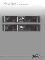
IPR
™
1600/3000/4500/6000
Power Amplifier
Congratulations on your purchase of an IPR power amplifier, designed for years of reliable, flawless operation under rigorous use. The
groundbreaking IPR series utilizes an advanced design that allows Peavey engineers to dramatically reduce weight while increasing
output power, reliability and thermal efficiency. IPR Series amplifiers are designed with a resonant switch-mode power supply and a
high-speed class D topology that yields the highest audio resolution and efficiency available. This revolutionary amplifier offers the
sonic superiority and unsurpassed reliability for which Peavey is famous, in an extremely efficient and lightweight design. Advanced
technology and extensive protection circuitry allow operation with greater efficiency into difficult loads and power conditions. The DDT
™
(Distortion Detection Technique) circuitry ensures trouble-free operation into loads as low as 2 ohms. DDT protects drivers and ensures
that sonic integrity is maintained, even in extreme overload conditions. The IPR’s high-efficiency design allows the amplifier to operate at
very low temperatures, and does not require massive heat sinks to cool. For your safety, read the important precautions section, as
well as input, output and power connection instructions.
Although the IPR amplifier is simple to operate and housed in an ultra-strong, ultra-lightweight chassis, improper use can be
dangerous. This amplifier is very highpowered and can put out high voltages and sizable currents at frequencies up to 30 kHz.
Always use safe operating techniques when operating this amplifier.
Before you send signal through your amplifier, it is very important to ensure that the product has the proper AC line voltage
supplied. You can find the proper voltage for your amp printed next to the IEC line (power) cord on the rear panel of the unit.
Each product feature is numbered. Refer to the front-panel diagram in this manual to locate the particular features next to its
number.
Please read this guide carefully to ensure your personal safety as well as the safety of your amplifier.
ENGLISH
VENTILATION: For proper ventilation, allow 12" clearance from nearest combustible surface.
Make sure that vents are not blocked and air can flow freely through the unit.
Features:
• 2 channel independent, fourth-order Linkwitz-Riley crossovers
• DDT protection
• Revolutionary IPR class D topology
• Detented input controls
• Combination XLR 1/4” inputs
• 4 pole twist lock output connectors
• Ultra-light weight
• Individual signal pass 1/4” jacks on each channel
• LED illuminated
• Standby, LED power present indication
WARNING: Changes or modifications to this unit not expressly approved by the party responsible for compliance
could void the user's authority to operate the equipment.
NOTE: This equipment has been tested and found to comply with the limits for a Class B digital device, pursuant to
Part 15 of the FCC Rules. These limits are designed to provide reasonable protection against harmful interference in
a residential installation. This equipment generates, uses and can radiate radio frequency energy and if not installed
and used in accordance with the instructions, may cause harmful interference to radio communications.
However, there is no guarantee that interference will not occur in a particular installation. If this equipment does
cause harmful interference to radio or television reception, which can be determined by turning the equipment off and
on, the user is encouraged to try to correct the interference by one or more of the following measures:
• Reorient or relocate the receiving antenna.
• Increase the separation between the equipment and receiver.
• Connect the equipment into an outlet on a circuit different from that to which the receiver is connected.
• Consult the dealer or and experienced radio/TV technician for help.
16

17
AC POWER SWITCH
This button triggers the relay that provides power to the amplifier. This unique power switch will glow blue (along with the
Peavey logo) in standby mode, indicating AC power has been connected to the amplifier but the amplifier has not yet been
turned on.
INDICATORS
The IPR
™
amplifiers feature five front-panel LED indicators per channel: ACTIVE, SIGNAL, DDT
™
, TEMP and DC. These LED
indicators inform the user of each channel’s operating status and warn of possible abnormal conditions.
ACTIVE LED
The Active LED indicates that its channel’s output relay is closed and the channel is operational. It lights under normal
operation and remains on, even when the channel is in DDT gain reduction. These protection features leave the output
relay closed. If the Active LED goes off, there is no signal at the output connectors.
SIGNAL LED
This LED lights when its channel produces an output signal of about 4 volts RMS or more (0.1 volt or more at the input,
with 0 dB attenuation and standard x40 voltage gain). This signal indicates whether a signal is reaching and being
amplified by the amplifier.
DDT
™
(DISTORTION DETECTION TECHNIQUE) LED
A channel’s DDT LED will light at the onset of clipping. If the LEDs are flashing quickly and intermittently, the channel is
just at the clip threshold. A steady, bright glow means the amp is clip limiting, or reducing gain to prevent severely clipped
waveforms from reaching the loudspeakers. See the Distortion Detection Technique section for more information. During
initial power-up the DDT LED will light to indicate that the RAMPUP
™
gain reduction circuitry is activated. This prevents
sudden signal bursts when the speaker relays are closed.
TEMP LED
In the unlikely event of an unstable thermal condition, amplifier protection will be activated and will shut down the
offending channel. The Temp LED will remain illuminated until safe operating temperatures have returned.
DC LED
In the event of abnormal operating conditions, the IPR has built-in amplifier protection. Under conditions that would
normally damage the power amplifier, the DC LED will illuminate and the channel will automatically attempt to restart to
correct the condition. If the amplifier does not return to normal operating status, contact your local authorized service
center.
INPUT ATTENUATORS
Whenever possible, set the attenuators fully clockwise to maintain optimum system headroom. The input attenuator
controls, located at the front panel (one for channel A, one for channel B), adjust gain for their respective amplifier
channels in all modes. See the specifications at the end of this manual for standard voltage gain and input sensitivity
information.
Front Panel
1
2
3
4
5
6
7
8
1
8 8
7
3
4
5
6
2
17

18
910
10
AC POWER INLET:
This is the receptacle for an IEC line cord, which provides AC power to the unit. Connect the line cord to this
connector to provide power to the unit. Damage to the equipment may result if improper line voltage is used.
(See line voltage marking on unit).
Never break off the ground pin on any equipment. It is provided for your safety. If the outlet used does not
have a ground pin, a suitable grounding adapter should be used and the third wire should be grounded
properly. To prevent the risk of shock or fire hazard, always make sure that the amplifier and all associated
equipment is properly grounded.
NOTE: FOR U.K. ONLY
As the colors of the wires in the mains lead of this apparatus may not correspond with the colored markings
identifying the terminals in your plug, proceed as follows: (1) The wire which is colored green and yellow
must be connected to the terminal which is marked by the letter E, or by the Earth symbol, or colored green
or green and yellow. (2) The wire which is colored blue must be connected to the terminal which is marked
with the letter N, or the color black. (3) The wire which is colored brown must be connected to the terminal
which is marked with the letter L, or the color red.
CHANNEL MODE SWITCH
HIGH PASS
This position is used to activate the HIGH PASS filter for the corresponding channel. This Linkwitz -Riley
filter will limit the frequencies sent to the associated amplifier channel to those frequencies above 100 Hz. In
situations where separate subwoofer cabinets are being used, this position would indicate connecting the
mid-high frequency speaker cabinet to the channel associated with the HIGH PASS switch.
FULL RANGE
As the name implies, the Full Range position on this switch allows all frequencies to pass to the amplifier.
Normally used when connecting a full range speaker enclosure to the amplifier's output.
SUBWOOFER
This position is used to activate the LOW PASS filter for the corresponding channel. This Linkwitz-Riley filter
will limit the frequencies sent to the associated amplifier channel to those frequencies below 100 Hz. In
situations where separate subwoofer cabinets are being used, this position would indicate connecting the
subwoofer speaker cabinet to the channel associated with the Subwoofer switch.
9
10
Rear Panel

19
Rear Panel
12
11
13
14
THRU/OUT JACKS
This 1/4” jack supplies parallel output signals from the associated channel for patching to this amplifier and/or additional
power amplifier inputs. The Thru/Out jack is affected by the position of the associated Channel Mode switch. This 1/4”
jack also provides an unbalanced (tip/sleeve) output to be patched with single-conductor shielded cables.
CONNECTING INPUTS
Input connections are made via the 3-pin XLR (pin 2+) or 6.3 mm plug combination connectors on the rear panel of the amplifier.
The inputs are actively balanced. The input overload point is high enough to accept the maximum output level of virtually any
signal source.
CONNECTING OUTPUTS
All models have one combination 4 pole twist lock output connector per channel. While a 1/4” speaker cable may be connected to
this output, the 4 pole twist lock output connection is the preferred method.
CIRCUIT BREAKER
In the unlikely event of operating conditions that may potentially damage the amplifier, the circuit breaker may trip. After inspecting
the cables and connections, the amplifier can be reset. If the circuit breaker trips a second time, contact the local Peavey authorized
service center.
11
12
13
13
12
11
14

20
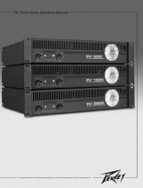
IPR
™
1600/3000/4500/6000 DSP
Power Amplifier
As the name implies, the IPR 1600, 3000, 4500, and 6000 DSP all include advanced digital signal processing. The DSP was
designed to be incredibly effective, yet extremely easy to use. Using unique and revolutionary advanced bass enhancement
processes, the IPR DSP amplifiers dramatically improve the perceived level of bass in any system, using a fraction of the power
that would be required with any other power amp.
Before you send signal through your amplifier, it is very important to ensure that the product has the proper AC line voltage
supplied. You can find the proper voltage for your amp printed next to the IEC line (power) cord on the rear panel of the unit.
Each product feature is numbered. Refer to the front panel diagram in this manual to locate the particular features next to its
number.
Please read this guide carefully to ensure your personal safety as well as the safety of your amplifier.
ENGLISH
IPR DSP Features:
• DDT
™
protection
• Revolutionary IPR class D topology
• Detented input controls
• Combination XLR 1/4” inputs
• Combination 1/4” or 1/4” 4 pole twist lock output connector
• Light weight
• Individual signal pass-thru 1/4” jacks on each channel
• LED illuminated
• DSP-based Loudspeaker Management System
• 120 ms of delay per channel
• 4 bands of parametric equalization per channel
• Security lock
• Adjustable fourth-order Linkwitz-Riley Crossover
• Adjustable fourth-order high-pass lter each channel
• Setup wizard
• MAXX Bass
®
• Horn EQ each channel
• Blue, backlit LCD screen
WARNING: PLEASE REVIEW YOUR DSP SETTINGS BEFORE SENDING SIGNAL TO THE AMPLIFIER. INCORRECT
SETTINGS CAN POTENTIALLY DAMAGE SPEAKER ENCLOSURES. We have made every attempt to ensure the Setup
Wizard will help correctly configure the DSP; however, incorrect settings at any point of the setup process can
damage your speaker enclosures. If you have any questions, please no not hesitate to call our customer service line.
VENTILATION: For proper ventilation, allow 12" clearance from nearest combustible surface.
Make sure that vents are not blocked and air can flow freely through the unit.
WARNING: Changes or modifications to this unit not expressly approved by the party responsible for compliance
could void the user's authority to operate the equipment.
NOTE: This equipment has been tested and found to comply with the limits for a Class B digital device, pursuant to
Part 15 of the FCC Rules. These limits are designed to provide reasonable protection against harmful interference in
a residential installation. This equipment generates, uses and can radiate radio frequency energy, and if not installed
and used in accordance with the instructions, may cause harmful interference to radio communications.
However, there is no guarantee that interference will not occur in a particular installation. If this equipment does
cause harmful interference to radio or television reception, which can be determined by turning the equipment off and
on, the user is encouraged to try to correct the interference by one or more of the following measures:
• Reorient or relocate the receiving antenna.
• Increase the separation between the equipment and receiver.
• Connect the equipment into an outlet on a circuit different from that to which the receiver is connected.
• Consult the dealer or and experienced radio/TV technician for help.
20

21
Getting Started with DSP
To navigate through the menus on the LCD screen, simply use the
push-button navigation encoder located to the right of the LCD screen.
The quickest and easiest way to congure any IPR
™
DSP model is to
use the Setup Wizard. After switching the unit on, the IPR DSP will
display the Setup Wizard entry screen for 6 seconds (Fig. 1). Turn the
encoder to "Yes" and depress to enter the Setup Wizard. If no input
is received after six seconds, the screen will advance to the main
operating menu.
SETUP WIZARD (Fig. 2)
If there are currently stored manual settings in the DSP, the LCD screen
will read “CLEAR MANUAL EQ SETTINGS?” This warning indicates there
have been changes made to the DSP in manual mode and continuing
through the Setup Wizard will erase the previously stored settings. To
continue through the wizard, select “YES.” Selecting “NO” will leave
the Setup Wizard and advance to the main operating menu.
Speaker Selection
The rst screen in the Setup Wizard allows the user to select the
speaker associated with each channel of the amplier. Rotate the
navigation encoder and press to select the speaker for each channel.
By selecting the speaker associated with each channel, the IPR
DSP can make certain assumptions and create optimal settings
for most circumstances with very little input from the user. The IPR
DSP includes a library of Peavey speakers, as well as some generic
selections for non-Peavey speakers. (Fig. 3)
After selecting speakers for each channel, if a subwoofer has not been
selected, the user will be prompted with, “DOES THE SYSTEM HAVE A
SUBWOOFER?” If “Yes” is selected, the amplier will assume it is part
of a two-way system with another amplier operating the subwoofer.
The IPR DSP will then assign a 100 Hz crossover to each channel,
allowing only those frequencies above 100 Hz to pass to the speaker
cabinets attached to the amplier. If a subwoofer was selected
during the setup process, the amplier will automatically assign the
appropriate crossover to each channel.
NOTE: In the Setup Wizard the crossover is automatically set at 100 Hz.
Enter Manual mode to adjust crossover frequency. (Fig. 4)
Fig. 1
Fig. 2
Fig. 3
Fig. 4
21

22
Setup Wizard
Fig. 5
Fig. 6
Setup Wizard Input Mode Select:
The IPR
™
DSP has the capability of routing the signal coming into
channel A to channel B for Mono operation. In the event the user
selects a mid-high cabinet for one channel and a subwoofer for the
other channel, the IPR DSP will make the assumption the amplier
is being used in Mono and will route the signal coming into channel
A to channel B, as well.
Otherwise, the user will be prompted to select the Input mode of
operation. Mono, as described above, will send the signal coming
from input A to both the A and B ampliers. (Fig. 5). In other words,
both channels will receive the signal coming from channel A. In
Stereo mode, each channel will receive an independent input.
Amplier A will use input A and amplier B will get signal from
Input B (Fig. 6).
Keep in mind the A and B 1/4” thru outputs are connected in
parallel with the A and B input connectors, respectively. This is
extremely helpful when running multiple ampliers. To preserve the
balanced input when using the thru output, use a TRS (Stereo) 1/4"
cable.
Any of these settings can be changed in Manual mode.

23
Setup Wizard
SETUP WIZARD EQ
EQ (or equalization) is designed to either make corrections to the
audio signal based on frequency anomalies in a particular room, or
to color the audio signal to adjust for a specic application. Many of
these application-style EQs color the signal path to represent the EQ
curve that would be typically associated with a style of music or a
specic application (such as speech). After speaker cabinet selection,
the IPR
™
DSP will ask the user if EQ is required (Fig. 7). If “Yes” is
selected the user will be able to scroll through several pre-designed
EQ curves that will give the user the general characteristics associated
with one of the following selections (Fig. 8):
Rock
Dance
Thump
DJ
Contemporary Worship
Speech
Setup Wizard Remote Speaker Delay
Delay is often required for systems with remote speakers. Occasionally
remote speakers are required for larger audiences. These speakers
can provide additional coverage in areas the main PA speakers do not
adequately cover. Unless the remote speakers are delayed properly
the audience will notice a time difference between the primary source
(main PA) and remote speaker. This time difference will be perceived
as an echo and will cause an undesirable listening environment. The
IPR DSP ampliers offer up to 120 mS of delay per channel, enough
to position the remote speakers up to 136 ft from the primary PA
speakers (Fig. 9).
When the amplier is congured to drive a Mono, two-way speaker
system, the delay adjustment changes both channels simultaneously.
Once in the delay screen, turn the navigation encoder to increase
or decrease the amount of delay. The screen displays the delay in
milliseconds, feet and meters (Fig. 10).
Fig. 7
Fig. 8
Fig. 9
Fig. 10
23

24
Setup Wizard
Setup Wizard Lock Settings:
The IPR
™
DSP allows the user to safely lock the settings of
the amplier after they have been congured. This feature can
be extremely useful when using the IPR DSP in an installation
environment, preventing unwanted changes to the settings that
can potentially damage the speakers. The user can chose whether
to disable the security lock, lock all of the settings, or ALL of the
settings EXCEPT the volume controls (input attenuators) (Fig.11).
If the security lock is engaged, users will be prompted to enter the
security code before being able to edit any of the DSP settings.
Once the correct access code has been entered, the control
screen will remain unlocked until the user either completes the
Setup Wizard or returns to the main menu (Fig.12). Please contact
Customer Service if the lock code is forgotten or misplaced.
NOTE: The IPR DSP input attenuators are actually encoders, unlike
the non-DSP version of the IPR, and are controlled by DSP.
Fig. 11
Fig. 12

25
Main Menu
Volume
Main Menu Settings
The Main Menu is divided into six sections, accessible by scrolling
right or left through the Main Menu options using the navigation
encoder (Fig. 13). Each menu item displays its current status. Press
the encoder over the selection to edit.
MODE
The IPR
™
DSP has the capability of routing the signal coming into
input A to both ampliers A and B for Mono operation (Fig. 14).
In Mono mode, both channels will receive the signal coming in
from channel A. In Stereo mode, each channel will receive and
independent input. Amplier A will use input A, and amplier B will
use input B (Fig. 15).
Keep in mind the 1/4” thru outputs can be used to route their
respective input signals to other to other ampliers. This is
extremely helpful when in sound systems with ampliers.
To preserve the balanced input when using the thru output, use
a TRS (stereo) 1/4" cable to route the "thru" signal to another
balanced input.
Volume:
The Main Menu displays the current settings for the volume
controls (0 being maximum) (Fig. 16)
NOTE
: The volume controls are really input attenuators and are
controlled by DSP.
Whenever possible, set the attenuators to maximum (0) to maintain
optimum system headroom. The input attenuator controls, located on
the front panel (one for channel A, one for channel B), adjust gain for
their respective amplifier channels in all modes. See the specifications
at the end of this manual for standard voltage gain and input sensitivity
information.
Scroll through menu using navigation encoder
Fig. 13
Fig. 14
Fig. 15
Fig. 16
25

26
Crossover
Crossover
The Main Menu displays the status of the crossover associated with each
channel, either OFF, HI or LOW. In the case of this illustration, channel
A indicates high frequencies are passing onto amplifier A. Channel B
indicates low frequencies are passing onto amplifier B (Fig. 17).
To adjust the crossover, press the navigation encoder while the cursor is
highlighting “XVR.”
NOTE: INCORRECT CROSSOVER SETTINGS MAY DAMAGE YOUR
SPEAKERS! Use speaker manufacturer’s recommended settings to
avoid potential damage.
Crossover Edit mode allows the user to remove, add or adjust the
crossover point. Select the desired crossover frequency and press the
navigation encoder (Fig. 18). To turn OFF the crossover function, lower the
crossover frequency until "None - Full Range" appears on the screen.
Once the crossover frequency has been selected, set the frequency
range that channels A and B each receive. Press the navigation encoder
to select and advance (Fig. 19). These screens will not appear if the
crossover is turned off.
The next menu allows the selection of a high-pass filter for each channel.
This filter reduces unwanted, potentially energy-robbing low-end
frequencies from entering the system (Fig. 20). Setting an appropriate
high-pass filter frequency also helps protect the loudspeaker from
damage and adjusts the frequency range of the Maxx bass processor.
Fig. 18
Fig. 19
Fig. 20
Fig. 17

27
EQ
EQ
The EQ section of the Main Menu indicates whether the EQ is active
on each channel. Pressing the navigation encoder when the cursor
highlights “EQ” will enter EQ Edit mode. Each channel has 4 parametric
EQs , horn equalization and enhanced bass processing (Fig. 21).
After entering Edit mode, the user will be able to activate or deactivate
the EQ on each channel. Press the navigation encoder to move the
cursor from EQ to channel A, then select ON or BYPASS. Repeat for
channel B (Fig. 22).
Turn the navigation encoder to the right to navigate to the BASS
ENHANCEMENT SCREEN. Press and select to adjust the amount of BASS
ENHANCEMENT (Fig. 23).
MaxxBass
®
uses psycho-acoustics to calculate precise harmonics
that are related to the fundamental tones of sound. The harmonics
are generated mostly from low-bass that is below the high-pass filter
setting. When these harmonics are combined, it creates the effect of
lower, deeper frequencies.
• Extends perceived bass response by up to 1.5 octaves
• Preserves the dynamic range and character of the original bass
Fig. 21
Fig. 22
Fig. 23
27

28
Parametric EQ
Parametric equalizers allow precise control of the amplitude, center
frequency and bandwidth of these bell response filters.
Each channel of the amplifier has four bands of parametric EQ. These
EQs can be used to compensate for peaks and dips in the frequency
response of certain speakers, eliminate feedback, and reduce or
enhance any area of the frequency spectrum. The attached frequency
diagram will help identify the frequencies that may need to be adjusted.
Each parametric EQ has three adjustable parameters:
Amplitude: the level of increase or decrease in decibels (cut or boost up
to 15 dB)
Frequency: the center frequency of the bandwidth being adjusted.
Bandwidth: the width of the frequency band being adjusted. The
bandwidth control is adjustable from a narrow 3/10 of an octave for
precise filtering to a wide 2 octaves for broad control.
To adjust each EQ simply scroll to the desired EQ and press the
navigation encoder to adjust each parameter (Fig. 24). Repeat for each
of the four EQs on channel A and B.
HORN EQ
The horn equalization in the IPR
™
DSP provides a gentle, rising
high-frequency boost to compensate for the roll-off inherent to most
high frequency horns. Adjust the frequency and level to achieve the
desired response. (Fig. 25)
Fig. 24
Fig. 25

29
Delay
Delay:
The Delay screen on the Main Menu indicates how much delay is
present on each channel in milliseconds. To enter Delay Edit mode,
highlight “DLY” with the cursor and press the navigation encoder
(Fig. 26).
Delay is often required for systems with remote speakers.
Occasionally remote speakers are required for larger audiences.
These speakers can provide additional coverage in areas that the
main PA speakers are not adequate. Unless the remote speakers
are delayed properly, the audience will notice a time difference
between the primary source (main PA) and remote speaker. This time
difference will be perceived as an echo and will cause an undesirable
listening environment. The IPR
™
DSP amplifiers offer up to 120 mS
of delay per channel, enough to position the remote speakers up to
136 ft from the primary PA speakers.
Once in the delay screen, turn the navigation enconder to increase
or decrease the amount of delay. The screen displays the delay in
milliseconds, feet and meters.
Fig. 26
29

30
Lock Settings
Lock Settings:
The IPR
™
DSP allows the user to safely lock the settings of the
amplifier (Fig. 27). This feature can be extremely useful when using the
IPR DSP in an installation environment, preventing unwanted persons
from changing the settings and potentially damaging the speakers. The
user can choose to disable the security lock, lock ALL DSP settings, or
lock ALL of the settings EXCEPT the volume controls (input attenuators).
If the security lock is engaged, users will be prompted to enter the
security code before being able to edit any of the DSP settings. The
control screen will automatically relock when the user returns to
the main menu. Please contact Customer Service if the lock code is
forgotten or misplaced.
After selecting the type of lock, set a four-digit security code to engage
the security feature. It is always best to record the access code in a safe
place for future reference.
AUTOMATIC STORAGE OF DSP SETTINGS
When using the Setup Wizard, audio processing is not changed and
the settings are not stored until setup is complete. None of the Wizard
settings will be stored if the amplifier is turned off before completing
the Wizard setup. The amplifier will return to previous settings when
next powered on.
When manually editing DSP parameters, the DSP processing will reflect
changes as they are made. Changes are then automatically stored by
returning to the Main Menu. Turning off the power before returning to
the Main Menu will erase the changes made and return to the previous
settings.
Fig. 27

31
IPR
™
1600 Specication Sheet
Rated Power (2 x 2 ohms) - 800 watts per channel @ 1 kHz at <0.1% T.H.D. both channels driven.
Rated Power (2 x 4 ohms) - 530 watts per channel @ 1 kHz at <0.1% T.H.D. both channels driven.
Rated Power (2 x 8 ohms) - 300 watts per channel @ 1 kHz at <0.1% T.H.D. both channels driven.
Rated Power (1 x 2 ohms) - 1000 watts @ 1 kHz at <0.1% T.H.D.
Rated Power (1 x 4 ohms) - 600 watts @ 1 kHz at <0.1% T.H.D.
Rated Power (1 x 8 ohms) - 320 watts @ 1 kHz at <0.1% T.H.D.
Minimum Load Impedance - 2 ohms
Maximum RMS Voltage Swing - 55 volts
Frequency Response - 10 Hz - 50 kHz; +0, -3 dB at 1 watt
T.H.D. (2 x 2 ohms) - <0.1% @ 600 watts per channel from 20 Hz to 1.5 kHz, decreasing to 500 watts at 20 kHz at <0.25%
T.H.D. (2 x 4 ohms) - <0.1% @ 470 watts per channel from 20 Hz to 20 kHz
T.H.D. (2 x 8 ohms) - <0.1% @ 250 watts per channel from 20 Hz to 20 kHz
Input CMRR - > - 60 dB @ 1 kHz
Voltage Gain - x 60 (+35 dB)
Crossover - 100 Hz switchable 2nd order High pass and 3rd order Low Pass per channel
Crosstalk - > -70 dB @ 1 kHz at 100 watts power @ 4 ohms
Hum and Noise - > -105 dB, "A" weighted referenced to rated power @ 4 ohms
Damping Factor (8 ohms) - > 170:1 @ 20 Hz - 1 kHz at 8 ohms
Phase Response - +9 to - 86 degrees from 20 Hz to 20kHz
Slew Rate: - > 12V/us
Input Sensitivity - .775 volts +/- 3% for 1 kHz 4 ohm rated power, .68 volts +/- 3% for 1 kHz. 2 ohm rated power
Input Impedance - 15k ohms, balanced and 7.5k ohms unbalanced.
Current Draw @ 1/8 power - 550 watts @ 2 ohms, 390 watts @ 4 ohms, 250 watts @ 8 ohms
Current Draw @ 1/3 power -1,160 watts @ 2 ohms, 810 watts @ 4 ohms, 460 watts @ 8 ohms
Cooling - Temperature dependent variable speed 80 mm DC fan
Controls - 2 front panel attenuators, crossover select switch for H.P.F, Normal and L.P.F.
Indicator LEDs - 2 DDT (clip limiting), 2 Signal presence, 2 Active status, 2 Temp and 2 DC protect
Protection - Thermal, DC, subsonic, incorrect loads, under and over voltage
Connectors - Inputs: Dual Combi 1/4” XLR, Outputs: Dual 1/4” signal patch, dual Speakon connectors
Construction - 0.062” thick aluminum
Dimensions - 3.5”x19” x 10.5” behind front panel + 0.6” for handle
Dimensions Packed - 4.72” x20.8” x 12.44” (120mm x 530mm x 316mm)
Net Weight* - 3.23 kg (7.125 lbs.)
Gross Weight - 4.31 kg (9.5 lbs.)
Warranty - 5 years
Rated power readings made with BW: <10 Hz to 22 kHz. All power measurements made at 120 VAC and 240VAC.
2 ohm power is time limited by circuit breaker.
*Net Weight does not include power cord.
31

32
IPR-1600 DSP Specification Sheet
Rated Power (2 x 2 ohms) - 900 watts per channel @ 1 kHz 1% T.H.D. both channels driven.
Rated Power (2 x 4 ohms) - 515 watts per channel @ 1 kHz at <0.1% T.H.D. both channels driven.
Rated Power (2 x 8 ohms) - 290 watts per channel @ 1 kHz at <0.1% T.H.D. both channels driven.
Rated Power (1 x 2 ohms) - 1050 watts @ 1 kHz at <1% T.H.D.
Rated Power (1 x 4 ohms) - 570 watts @ 1 kHz at <0.1% T.H.D.
Rated Power (1 x 8 ohms) - 300 watts @ 1 kHz at <0.1% T.H.D.
Minimum Load Impedance - 2 ohms.
Maximum RMS Voltage Swing - 55 volts.
Frequency Response - 10 Hz - 22 kHz, +/- 0.5 dB at 1 watt.
T.H.D. (2 x 2 ohms) - <0.1% @ 675 watts per channel from 20 Hz to 1 kHz, decreasing to 500 watts at 20 kHz at <0.25%.
T.H.D. (2 x 4 ohms) - <0.1% @ 510 watts per channel from 20 Hz to 11 kHz, decreasing to 425 watts at 20 kHz at same <0.1%.
T.H.D. (2 x 8 ohms) - <0.1% @ 270 watts per channel from 20 Hz to 20 kHz.
Input CMRR - > - 69 dB @ 1 kHz.
Voltage Gain - x 40 (+32dB).
Crossover - Adjustable frequencies with 24dB/oct, 4
th
order Linkwitz –Riley High Pass and Low Pass filter per channel
Crosstalk - > -70 dB @ 1 kHz at 250 watts power @ 8 ohms.
Hum and Noise - > -92 dB, "A" weighted referenced to rated power @ 4 ohms.
Slew Rate - > 12V/μs.
Damping Factor (8 ohms) - > 150:1 @ 20 Hz - 1 kHz at 8 ohms.
Input Sensitivity - 1.14 volts +/- 3% for 1 kHz 4 ohm rated power, 1.07 volts +/- 3% for 1 kHz. 2 ohm rated power.
Input Impedance - 15k ohms, balanced and 7.5k ohms unbalanced.
Current Draw @ 1/8 power - 540 watts @ 2 ohms, 350 watts @ 4 ohms, 230 watts @ 8 ohms.
Current Draw @ 1/3 power - 1,250 watts @ 2 ohms, 740 watts @ 4 ohms, 450 watts @ 8 ohms.
Cooling - Temperature dependent variable speed 80 mm DC fan.
Controls - 2 front panel detented attenuators, push-button navigation encoder to navigate through the menus on the
LCD screen for input mode, parametric EQ, crossover H.P.F, Normal, L.P.F. and more.
Indicator LEDs - 2 DDT (clip limiting), 2 Signal presence, 2 Active status, 2 Temp and 2 DC protect.
Protection - Thermal, DC, subsonic, incorrect loads, under and over voltage.
Connectors - Inputs: Dual Combi 1/4” & XLR, Outputs: Dual 1/4” signal patch, dual twist locking connectors.
Construction - 0.062” thick aluminum.
Dimensions - 3.5”x19”x 10.5” behind front panel + 0.6” for handle.
Net Weight - 3.23 kg (7.12 lbs.*)
Gross Weight - 4.31 kg (9.5 lbs.)
Warranty - 5 years.
Rated power readings made with BW: <10 Hz to 22 kHz. All power measurements made at 120 VAC and 240VAC.
2 ohm power is time limited by circuit breaker.
*Net Weight does not include power cord.
/