8-Sp
CHN10202
Manual de Instrucciones
tion equipment such as head, hear-
ing and foot protection equipment.
Serious eye or permanent hearing
loss could result.
• Assuring that the tool is kept in
safe working order as described in
this manual.
• Assuring the proper maintenance
of all tools in employer’s possession.
• Ensuring that tools which require
repair are not further used before
repair. Tags and physical segrega-
tion are recommended means of
control.
Table of Contents
General Safety . . . . . . . . . . . . . . . .1-3
Specifications . . . . . . . . . . . . . . . . . .2
Operating The Nailer . . . . . . . . . .3-5
Operational Mode . . . . . . . . . . . . . .4
Troubleshooting . . . . . . . . . . . . . . . .7
Warranty . . . . . . . . . . . . . . . . . . . . . .8
Description
This nailer is designed for decorative
trim, molding, window casings, furni-
ture trim and picture frame assembly.
Features include: no-mar tip,
adjustable exhaust, single sequential
trigger, quick clear nose, and an
adjustable depth of drive mechanism.
General Safety
Information
CALIFORNIA PROPOSITION 65
You can create dust when
you cut, sand, drill or grind
materials such as wood,
paint, metal, concrete, cement, or other
masonry. This dust often contains chemi-
cals known to cause cancer, birth
defects, or other reproductive harm.
Wear protective gear.
This prod-
uct or its power cord contains chemi-
cals known to the State of California to
cause cancer and birth defects or other
reproductive harm. Wash hands after
handling.
This manual contains safety, opera-
tional and maintenance information.
Contact your Campbell Hausfeld repre-
sentative if you have any questions.
OPERATOR’S RESPONSIBILITY:
The tool operator is responsible for:
• Reading and understanding tool
labels and manual.
• Selecting an appropriate tool actua-
tion system, taking into considera-
tion the work application for which
the tool is used.
• The safe use of the tool.
• Ensuring that the
tool is used only
when the operator
and all other person-
nel in the work area
are wearing ANSI Z87 eye protec-
tion equipment, and when
required, other appropriate protec-
tion equipment such as head, hear-
ing and foot protection equipment.
Serious eye or permanent hearing
loss could result.
• Assuring that the tool is kept in safe
working order as described in this
manual.
EMPLOYER’S RESPONSIBILITY:
• Selecting an appropriate tool actua-
tion system, taking into considera-
tion the work application for which
the tool is used.
• Ensuring that this manual is avail-
able to operators and personnel
performing maintenance.
• The safe use of the tool.
• Enforcing that the
tool is used only
when the operator
and all other person-
nel in the work area
are wearing ANSI Z87 eye protec-
tion equipment, and when
required, other appropriate protec-
Operating Instructions CHN10202
2” Brad Nailer
Please read and save these instructions. Read carefully before attempting to assemble, install, operate or maintain the product described.
Protect yourself and others by observing all safety information. Failure to comply with instructions could result in personal injury, death and/or
property damage! Retain instructions for future reference.
Model CHN10202
IN276801AV 7/08
Campbell Hausfeld Nailers meet or exceed
Industries’ Standards as set forth by the
American National Standard
Institute/International Staple, Nail and Tool
Association in ANSI/ISANTA SNT-101-2002.
© 2008 Campbell Hausfeld/Scott Fetzer
See Warranty on page 8 for important information about commercial use of this product.
REMINDER: Keep your dated proof of purchase for warranty purposes! Attach it to this manual or file it for safekeeping.
For parts, product & service information
visit www.chpower.com
Locate model and vendor date code
on tool magazine and cap and record
below:
Model No. ________________________
Date Code.________________
Retain these numbers for
future reference.
Garantía Limitada
1 DURACION: A partir de la fecha de compra por el comprador original tal como se especifica a continuación: Productos
Estándard (Standard Duty) - Un año, Productos Resistentes (Serious Duty) -Dos años, Productos Robustos (Extreme Duty)
- Tres años.
2. QUIEN OTORGA ESTA GARANTIA (EL GARANTE: Campbell Hausfeld / The Scott Fetzer Company 100 Production Drive,
Harrison, Ohio 45030 Teléfono: (800) 543-6400
3. QUIEN RECIBE ESTA GARANTIA (EL COMPRADOR): El comprador original (que no sea un revendedor) del producto
Campbell Hausfeld.
4. PRODUCTOS CUBIERTOS POR ESTA GARANTIA: Cualquier clavadora, grapadora, herramienta neumática, pistola pulver-
izadora, inflador o accesorio neumático suministrado o fabricado por el Garante.
5. COBERTURA DE LA GARANTIA: Los defectos substanciales de material y fabricación que ocurran dentro del período de
validez de la garantía.
6. LO QUE NO ESTA CUBIERTO POR ESTA GARANTIA:
A. Las garantías implícitas, incluyendo aquellas de comercialidad E IDONEIDAD PARA FINES PARTICULARES, ESTAN
LIMITADOS A LO ESPECIFICADO EN EL PARRAFO DE DURACION. Si este producto es empleado para uso comercial,
industrial o para renta, la garantía será aplicable por noventa (90) días a partir de la fecha de compra. En algunos
estados no se permiten limitaciones a la duración de las garantías implícitas, por lo tanto, en tales casos esta lim-
itación no es aplicable.
B. CUALQUIER PERDIDA DAÑO INCIDENTAL, INDIRECTO O CONSECUENTE QUE PUEDA RESULTAR DE UN DEFECTO,
FALLA O MALFUNCIONAMIENTO DEL PRODUCTO CAMPBELL HAUSFELD. En algunos estados no se permite la
exclusión o limitación de daños incidentales o consecuentes, por lo tanto, en tales casos esta limitación o exclusión
no es aplicable
C. Cualquier falla que resulte de un accidente, abuso, negligencia o incumplimiento de las instrucciones de fun-
cionamiento y uso indicadas en el (los) manual(es) que se adjunta(n) al producto. Dichos accidentes, abusos por
parte del comprador, o falta de operar el producto siguiendo las instrucciones del manual de instrucciones sumin-
istrado también debe incluir la desconexión o modificación de los instrumentos de seguridad. Si dichos instrumen-
tos de seguridad son desconectados, la garantía quedaría cancelada.
D. Los ajustes normales explicados en el(los) manual(es) suministrado(s) con el producto.
E. Artículos o servicios normalmente requeridos para el mantenimiento del producto, tales como: anillos en O,
resortes, amortiguadores, defensas, hojas de impulsor, fusibles, baterías
, empaques, almohadillas o sellos, boquillas
de fluído, agujas, boquillas para rociar arena, lubricantes
, mangueras de material, elementos filtrantes, álabes de
motores, abrasivos, hojillas, discos para cortar, cinceles, retenes para cinceles, cortadores, collarines, mandriles, mor-
dazas para remachadoras, brocas para desarmadores, almohadillas para lijar
, soportes de almohadillas, mecanismo
de impacto o cualquier otro artículo desgastable que no se haya enumerado específicamente . Estos artículos sólo
estarán cubiertos bajo esta garantía por noventa (90) días a partir de la fecha de compra original. Los artículos sub
-
rayados sólo están garantizados por defectos de material o fabricación.
7. RESPONSABILIDADES DEL GARANTE BAJO ESTA GARANTIA: Reparar o reemplazar, como lo decida el Garante, los pro-
ductos o componentes que estén defectuosos, se hayan dañado o hayan dejado de funcionar adecuadamente, durante
el período de validez de la garantía
8. RESPONSABILIDADES DEL COMPRADOR BAJO ESTA GARANTIA:
A. Suministrar prueba fechada de compra y la historia de mantenimiento del producto.
B. Entregar o enviar el producto o componente Campbell Hausfeld al Centro de Servicio autorizado Campbell
Hausfeld más cercano. Los gastos de flete, de haberlos, deben ser pagados por el comprador.
C. Seguir las instrucciones sobre operación y mantenimiento del producto, tal como se indica(n) en el (los) manual(es)
del propietario
9. CUANDO EFECTUARA EL GARANTE LA REPARACION O REEMPLAZO CUBIERTO BAJO ESTA GARANTIA: La reparación o
reemplazo dependerá del flujo normal de trabajo del centro de servicio y de la disponibilidad de repuestos.
Esta garantía limitada es válida sólo en los EE.UU., Canadá y México y otorga derechos legales específicos. Usted también
puede tener otros derechos que varían de un Estado a otro. o de un país a otro.

7-Sp
Manual de Instrucciones
CHN10202
Hay una fuga de aire en el
área de la válvula del gatillo
Hay una fuga de aire entre
la cubierta y la boquilla
Hay una fuga de aire entre
la cubierta y la tapa
La clavadora deja de clavar
un clavo
La clavadora funciona lenta-
mente o pierde su potencia
Hay clavos atascados en la
clavadora
Hay una fuga de aire en el
vástago de la válvula del
gatillo
Los anillos en O de la cubierta de la válvula
del gatillo están dañados
Los anillos en O están dañados
La cubierta está dañada
Los tornillos están flojos
El empaque está dañado
La cubierta está desgastada
La boquilla está sucia
La suciedad o daños evitan el desplazamien
to libre de los clavos o el mecanismo de
impulso en el cargador
El resorte del mecanismo de impulso está
dañado
El flujo de aire hacia la clavadora es inade-
cuado
El anillo en O del pistón está desgastado o le
falta lubricación
Los anillos en O de la válvula del gatillo
están dañados
Hay fugas de aire
Hay una fuga en el empaque de la tapa
La clavadora no está bien lubricada
El resorte de la tapa del cilindro está roto
El orificio de salida de la tapa está obstruído
La guía del mecanismo de impulso está desgas
tada
Los clavos no son del tamaño adecuado.
Los clavos están doblados
Los tornillos del cargador o de la boquilla están
flojos
El mecanismo de impulso está dañado
Los anillos en O o los sellos están dañados
Guía de Diagnóstico de Averías
Deje de usar la clavadora inmediatamente si alguno de los siguientes problemas ocurre.
Podría resultado en heridas graves. Cualquier reparación o reemplazo de piezas los debe hacer
un técnico calificado personal de un centro autorizado de servicio.
Problema Causa Solución
Debe reemplazar los anillos en O & chequear el funcion-
amiento del elemento de funcionamiento al contacto
Debe reemplazar los anillos en O
Debe reemplazar la defensa
Debe apretar los tornillos
Debe reemplazar el empaque
Debe reemplazar la cubierta
Debe limpiar el canal del sistema de impulso
Debe limpiar el cargador
Debe reemplazar el resorte
Cheque las conexiones, la manguera o el compresor
Debe reemplazar los anillos en O. Lubríquelos.
Debe reemplazar los anillos en O
Debe apretar los tornillos y las conexiones
Debe reemplazar el empaque
Necesita lubricar la clavadora
Debe reemplazar el resorte
Debe reemplazar las partes internas dañadas
Debe reemplazar la guía
Debe usar los clavos recomendados para esta clavadora
Reemplácelos con clavos en buenas condiciones
Debe apretar los tornillos
Debe reemplazar el mecanismo de impulse de clavos
Debe reemplazar los anillos en O o los sellos
2
General Safety
Information (Continued)
Danger
indicates
an imminently hazardous situation
which, if not avoided, WILL result in
death or serious injury.
● Read and understand
tool labels and manual.
Failure to follow warn-
ings, dangers, and cau-
tions could result in
DEATH or SERIOUS INJURY.
● Do not use any type
of reactive gases,
including, but not lim-
ited to, oxygen and
combustible gases, as
a power source. Use
filtered, lubricated, regulated com-
pressed air only. Use of a reactive
gas instead of compressed air may
cause the nailer to explode which
will cause death or serious personal
injury.
● Use only a pressure-
regulated compressed
air source to limit the
air pressure supplied
to the tool. The regu-
lated pressure must
not exceed 100 psi. If the regulator
fails, the pressure delivered to the
tool must not exceed 200 psi. The
nailer could explode which will
cause death or serious personal
injury.
● Never use gasoline
or other flammable
liquids to clean the
nailer. Never use the
nailer in the presence of flammable
liquids or gases. Vapors could ignite
by a spark and cause an explosion
which will result in death or serious
personal injury.
● Always remain in a
firmly balanced
position when
using or handling
the nailer.
● Do not remove, tam-
per with, or other-
wise cause the Work
Contact Element
(WCE) or trigger to
become inoperable.
Do not operate any
tool which has been modified in a
like fashion. Death or serious per-
sonal injury could result.
● Do not touch
the trigger
unless driving
nails. Never
attach air line
to nailer or
carry nailer
while touching the trigger. The tool
could eject a fastener which will
result in death or serious personal
injury.
Warning
indicates a
potentially hazardous situation which,
if not avoided, COULD result in death
or serious injury.
● Always discon-
nect the tool
from the power
source when
unattended,
performing any
maintenance or repair, clearing a
jam, or moving the tool to a new
location. Always reconnect the air
line BEFORE loading any fasteners.
Do not load the tool with fasteners
when either the trigger is depressed
or the Work Contact Element (WCE)
is engaged. The nailer could eject a
fastener causing death or serious
personal injury.
● Always fit tool
with a fitting or
hose coupling
on or near the
tool in such a
manner that all
compressed air
in the tool is discharged at the time
the fitting or hose coupling is dis-
connected. Do not use a check valve
or any other fitting which allows air
to remain in the nailer. Death or seri-
ous personal injury could occur.
● Never place hands or
any other body parts in
the nail discharge area
of the nailer. The nailer
might eject a fastener
and could result in
death or serious per-
sonal injury.
● Never carry the
nailer by the air
hose or pull the
hose to move the
nailer or a com-
pressor. Keep
hoses away from
heat, oil and sharp edges. Replace
any hose that is damaged, weak or
worn. Personal injury or tool dam-
age could occur.
CHN10202
Operating Instructions
www.chpower.com
O
CO
2
100
psi
BUILT TO LAST
BUILT TO LAST
BUILT TO LAST
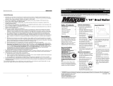
Latch
Magazine
Work contact
element (WCE)
Trigger
Nail loading area
Cap exhaust
Nailer Components and Specifications
• REQUIRES: 1.3 SCFM with 10
nails per minute @ 90 psi
• AIR INLET: 1/4 in. NPT
• NAIL SIZE RANGE: 5/8 in. to 2 in.
• MAGAZINE CAPACITY:
100 Nails per load, 18 gauge
• WEIGHT: 3 lb, 6 oz
• LENGTH: 11-1/4 in.
• HEIGHT: 10-1/2 in.
• MAXIMUM PRESSURE: 100 psi
• PRESSURE RANGE: 60 psi – 100 psi
BUILT TO LAST
Quick Clear
Nose Latch

6-Sp
Manual de Instrucciones
CHN10202
Clavos
Estos clavos para acabado de Campbell Hausfeld los puede comprar en su tienda más cercana. Si necesita ayuda para encon-
trar un artículo, comuníquese al 1-800-543-6400. Los clavos de Campbell Hausfeld cumplen o exceden el estándar ASTM F1667
Calibre Clavos por Clavos por
Modelo # Longitud
del cuerpo
Acabado Cabeza Unión
línea Caja
FB001600 15,9mm (5/8”) Calibre 18 Galvanizado De puntilla/Café Adhesivo 100 5000
FB002000 19,1mm (3/4”) Calibre 18 Galvanizado De puntilla/Café Adhesivo 100 5000
FB002500 25,4mm (1”) Calibre 18 Galvanizado De puntilla/Café Adhesivo 100 5000
FB003000 31,8mm (1
1
⁄
4”) Calibre 18 Galvanizado De puntilla/Café Adhesivo 100 5000
FB004000 3,81 cm(1
1
⁄
2”) Calibre 18 Galvanizado De puntilla/Café Adhesivo 100 5000
FB004500 4,45cm(1
3
⁄
4”) Calibre 18 Galvanizado De puntilla/Café Adhesivo 100 5000
FB005000 5,08cm (2”) Calibre 18 Galvanizado De puntilla/Café Adhesivo 100 5000
FB180016 15,9mm (5/8”) Calibre 18 Galvanizado De puntilla/Café Adhesivo 100 1000
FB180025 25,4mm (1”) Calibre 18 Galvanizado De puntilla/Café Adhesivo 100 1000
FB180030 31,8mm (1
1
⁄
4”) Calibre 18 Galvanizado De puntilla/Café Adhesivo 100 1000
FB180040 3,81 cm(1
1
⁄
2”) Calibre 18 Galvanizado De puntilla/Café Adhesivo 100 1000
FB180050 5,08cm (2”) Calibre 18 Galvanizado De puntilla/Café Adhesivo 100 1000
Información de intercambio
Puede usar clavos de las siguientes marcas de clavadoras para acabado neumáticas: Bostitch® BT125SK-2 & BT200K-2,
Campbell Hausfeld®NB0030 & NB0040, DeWalt® D51238K, Paslode® T125-F18 & T200-F18, Porter Cable® BN125 & BN200, y
Senco Finish Pro® 15 & 18.
9. Asegúrese de
que el gatillo
y el elemento
de contacto de
trabajo (WCE)
se muevan
libremente hacia arriba y hacia
abajo sin adherirse ni trabarse.
Servicio Técnico
Si desea hacer alguna pregunta refer-
ente a la reparación u operación de las
clavadoras, o para solicitar copias adi-
cionales de este manual, sírvase llamar
a nuestro número especial, 1-800-543-
6400.
Clavos y Refacciones
Use solamente clavos Campbell
Hausfeld originales calibre 18 (o su
equivalente) - (vea la información sobre
intercambio de clavos). El desempeño
de las herramientas, la seguridad y la
duración pueden disminuir si no se
utilizan los clavos adecuados. Cuando
ordene partes de repuesto o clavos,
especifique el número de la parte.
Para reparar la clavadora
La herramienta deberá ser reparada
únicamente por personal calificado, y
deberán usar piezas de repuesto y
accesorios originales Campbell
Hausfeld, o piezas y accesorios que
funcionen de manera equivalente.
Para colocarle los sellos
Cada vez que repare una clavadora
deberá limpiarle y lubricarle las partes
internas. Le recomendamos que use
Parker O-lube o un lubricante equiva-
lente en todos los anillos en O. A cada
anillo en O se le debe dar un baño de
lubricante para anillos antes de instalar-
los. Igualmente, deberá ponerle un
poco de aceite a todas las piezas que se
mueven y muñones. Finalmente,
después de haberla ensamblado y antes
de probar la herramienta deberá pon-
erle unas cuantas gotas de aceite sin
detergente 30W u otro aceite similar,
en las líneas de aire.
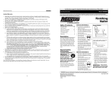
Recommended Hookup
Quick
Plug
Quick
Coupler
Air
Hose
Quick Plug
(Optional)
Quick
Coupler
(Optional)
Oiler
Regulator
Filter
3
General Safety
Information (Continued)
● Always assume the nailer contains
nails. Respect the tool as a working
implement; no horseplay. Always
keep others at a safe distance from
the work area in case of accidental
discharge of nails. Do not point the
tool toward yourself or anyone
whether it contains fasteners or not.
Accidental triggering of the nailer
could result in death or serious per-
sonal injury.
● Do not drive a
nail on top of
other nails. The
nail could glance
and cause death
or a serious punc-
ture wound.
● Do not operate
or allow anyone
else to operate
the nailer if any
warnings or
warning labels
are not legible.
Warnings or warning labels are locat-
ed on the nailer magazine and body.
● Do not drop or throw the tool.
Dropping or throwing the tool can
result in damage that will make the
tool unusable or unsafe. If the tool
has been dropped or thrown, exam-
ine the tool closely for bent, cracked
or broken parts and air leaks. STOP
and repair before using or serious
injury could occur.
Caution
indicates a
potentially hazardous situation which,
if not avoided, MAY result in minor or
moderate injury.
● Do not make any modifications to the
tool without first obtaining written
Operating The Nailer
LUBRICATION
This nailer requires lubrication before
using the nailer for the first time and
before each use. If an inline oiler is
used, manual lubrication through the
air inlet is not required on a daily basis.
The work
surface can
become damaged by excessive lubrica-
tion. Proper lubrication is the owner’s
responsibility. Failure to lubricate the
nailer properly will dramatically short-
en the life of the nailer and void your
warranty.
1. Disconnect the
air supply from
the nailer to
add lubricant.
2. Turn the nailer so the
air inlet is facing up.
Place 4-5 drops of 30
W non-detergent oil
into air inlet. Do not
use detergent oils, oil additives, or
air tool oils. Air tool oils contain sol-
vents which will damage the nailer's
internal compo-
nents.
3. After adding oil, run
nailer briefly. Wipe
off any excess oil
from the cap exhaust.
RECOMMENDED HOOKUP
The illustration below shows the
recommended hookup for the nailer.
approval from Campbell Hausfeld. Do
not use the nailer if any shields or
guards are removed or altered. Do
not use the nailer as a hammer.
Personal injury or tool
damage may occur.
● Avoid long extended periods of
work with the nailer. Stop using the
nailer if you feel pain in hands or
arms.
● Always check that the Work Contact
Element (WCE) is operating proper-
ly. A nail could accidentally be dri-
ven if the WCE is not working prop-
erly. Personal injury may occur (See
"Checking the Work Contact
Element" Section).
● Disconnect air supply and release
tension from the pusher before
attempting to clear jams because
fasteners can be ejected from the
front of the nailer. Personal injury
may occur.
Notice
indicates
important infor
mation, that if not fol-
lowed, MAY cause damage to equip-
ment.
● Avoid using the nailer when the
magazine is empty. Accelerated
wear on the nailer may occur.
● Clean and check all air supply hoses
and fittings before connecting the
nailer to an air supply. Replace any
damaged or worn hoses or fittings.
Tool performance or durability may
be reduced.
CHN10202
Operating Instructions
www.chpower.com
!
WARNING
BUILT TO LAST
BUILT TO LAST
BUILT TO LAST
BUILT TO LAST
Cómo usar la
Clavadora (Continuación)

Cómo usar la
Clavadora (Continuación)
7. Apriete el
gatillo y pre-
sione el
Elemento de
Contacto de Trabajo contra la
superficie de trabajo. La clavadora
NO DEBE hacerse funcionar.
8. Presione el
Elemento de
Contacto de
Trabajo con-
tra la superficie de trabajo. Apriete
el gatillo. La clavadora DEBE OPER-
AR.
Una
herramienta que funciona de manera
inadecuada no debe usarse. No active
la herramienta a menos que esté
colocada firmemente contra la pieza de
trabajo.
PARA CARGAR Y DESCARGAR LA
CLAVADORA
1. Siempre conecte la herramienta a
la fuente de suminsitro de aire
antes de colocarle los clavos.
2. Empuje el
cierre hacia
abajo. Mueva
la tapa del car-
gador hacia
atrás.
3. Coloque una
serie de clavos
Campbell
Hausfeld o
equivalentes
(Vea la sección de clavos) en el car-
gador. Cerciórese de que los
extremos puntiagudos de los clavos
estén hacia la parte inferior del car-
gador. Cerciórese de que los clavos
no estén sucios ni dañados.
4. Tire la tapa del
cargador hacia
adelante hasta
que calce el
pestillo.
5. Siempre descargue el sujetador
antes de remover la herramienta de
servicio. La descarga se hace
siguiendo el proceso inverso de la
carga; sin embargo, siempre se
tiene que desconectar la
manguera de aire antes de descar-
garla.
CÓMO AJUSTAR LA PENETRACIÓN
DEL CLAVO
La CHN10202 viene equipada con un
mecanismo clavador de profundidad
ajustable. Esto le permite al usuario
determinar a qué profundidad se va a
clavar en la superficie de trabajo.
1. Ajuste la presión de operación a aquél-
la que usará con regularidad para
clavar los clavos. No exceda la presión
de 6,90 bar.
2. Para dirigir el calador de clavos, gire
la rueda (C) hacia la derecha hasta
el punto deseado.
3. Para clavar el clavo más profundo,
gire la rueda (C) hacia la izquierda
hasta el punto deseado.
4. Asegúrese que el
gatillo y el Elemento
de Contacto de
Trabajo se mueven
libremente hacia
arriba y hacia abajo sin atascarse o
pegarse después de cada ajuste.
PARA AJUSTAR LA DIRECCION DEL
TUBO DE ESCAPE
La clavadora mod-
elo CHN10202 está
equipada con un
deflector ajustable
de la dirección del
tubo de escape. Éste le permite al
usuario cambiar la dirección del tubo
de escape. Simplemente mueva el
deflector hacia la dirección deseada.
QUÉ HACER CUANDO LA HERRA-
MIENTA TENGA UN SUJETADOR
ATASCADO
1. Desconecte la
clavadora de
la fuente de
suministro de
aire.
2. Remuezva
todos los clavos
del depósito
(vea “Carga/
Descarga de la
Clavadora”).
Si no se
retiran
todos los sujetadores éstos saldrán por el
frente de la herramienta.
3. Destrabe el
seguro halando
hacia afuera y
abajo. El seguro
de alambre se
destraba de los
ganchos de la boquilla.
4. Ahora se puede
girar la puerta,
dejando al
descubierto el
sujetador que
esté trabado.
5. Retire todos los
sujetadores que
estén trabados,
utilizando unas
pinzas o un
destornillador si
fuera necesario.
6 Vuelva a girar
la puerta a su
posición de
cerrado.
7. Extienda el
seguro de
alambre
y colóquelo
sobre los
ganchos de
la boquilla.
8. Cierre el seguro
empujándolo
hacia arriba y
adentro hasta
que quede a
presión en su
lugar.
CHN10202
5-Sp
Manual de Instrucciones
(C)
Operating The Nailer
(Continued)
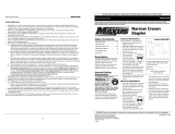
1. The air com-
pressor must
be able to
maintain a
minimum of 60
psi when the
nailer is being used. An inadequate
air supply can cause a loss of power
and inconsistent
driving.
2. An oiler can be
used to provide oil
circulation through
the nailer. A filter
can be used to
remove liquid and solid impurities
which can rust or “gum up” internal
parts of the nailer.
3. Always use air supply hoses with a
minimum working pressure rating
equal to or greater than the pres-
sure from the power source if a reg-
ulator fails, or 150 psi, whichever is
greater. Use 3/8” air hose for runs
up to 50’. Use 1/2” air hoses for 50’
run or longer. For better perfor-
mance, install a 3/8” quick plug
(1/4” NPT threads) with an inside
diameter of .315” (8mm) on the
nailer and a 3/8” quick coupler on
the air hose.
4. Use a pressure regulator on the
compressor, with an operating pres-
sure of 0 - 125 psi. A pressure regu-
lator is required to control the oper-
ating pressure of the nailer
between 60 and 100 psi.
OPERATIONAL MODE
Always
know the
operational mode of the nailer before
using. Failure to know the operational
ger. The nailer MUST NOT OPER-
ATE. Do not use the tool if it oper-
ates without pulling the trigger.
Personal injury may result.
6. Remove the nailer
from the work sur-
face. The Work
Contact Element
(WCE) must return to
its original down position. The nail-
er MUST NOT OPERATE. Do not
use the tool if it operates while lift-
ed from the work surface. Personal
injury may result.
7. Pull the trig-
ger and
depress the
work contact
element (WCE) against the work
surface. The nailer MUST NOT
OPERATE.
8. Depress the
Work Contact
Element
(WCE) against
the work surface. Pull the trigger.
The nailer MUST OPERATE.
An improp-
erly func-
tioning tool must not be used. Do not
actuate the tool unless the tool is
placed firmly against the work piece.
LOADING/UNLOADING THE NAILER
1. Always connect the tool to the air
supply before loading fasteners.
2. Push down on
the latch. Pull
back on the
magazine cover.
3. Insert a stick of
Campbell
Hausfeld nails
or equivalent
(see "Fasteners" section) into the
magazine. Make sure the pointed
ends of the nails are resting on the
bottom ledge of the magazine
when loading. Make sure the nails
are not dirty or damaged.
mode could result in death or serious
personal injury.
SINGLE SEQUENTIAL MODE
This mode
requires the trig-
ger to be pulled
each time a nail
is driven. The nailer can be actuated by
depressing the WCE against the work
surface followed by pulling the trigger.
The trigger must be released to reset
the tool before another nail can be dri-
ven.
OPERATING A SEQUENTIAL TRIP
NAILER
Check the
operation
of the Work Contact Element (WCE) trip
mechanism before each use. The WCE
must move freely without binding
through its entire travel distance. The
WCE spring must return the WCE to its
fully extended position after being
depressed. Do not operate the nailer if
the WCE trip mechanism is not operat-
ing properly. Personal injury may occur.
1. Disconnect the
air supply from
the nailer.
2. Remove all
nails from the
magazine (see
Loading/
Unloading).
3. Make sure the trig-
ger and work con-
tact element (WCE)
move freely up and
down without stick-
ing or binding.
4. Reconnect air
supply to the
nailer.
5. Depress the Work
Contact Element
(WCE) against the
work surface with-
out pulling the trig-
CHN10202
Operating Instructions
4
www.chpower.com
60 psi
Min.
100 psi
Max.
150 psi or greater
3/8” I.D.
BUILT TO LAST
BUILT TO LAST
BUILT TO LAST
BUILT TO LAST
BUILT TO LAST
movement
BUILT TO LAST
BUILT TO LAST
BUILT TO LAST
BUILT TO LAST
1
2
BUILT TO LAST
BUILT TO LAST
1
2
BUILT TO LAST
BUILT TO LAST
Latch
BUILT TO LAST
BUILT TO LAST
1
2
BUILT TO LAST
BUILT TO LAST
1
2
BUILT TO LAST
BUILT TO LAST
Pestillo
BUILT TO LAST
movemiento
Gire

Cómo usar la
Clavadora (Continuación)
1. Desconecte la
clavadora de la
fuente de sum-
inistro de aire
para lubricarla.
2. Gire la clavadora de
modo que la entrada
de aire quede miran-
do hacia arriba.
Agregue de 4 a 5
gotas de aceite sin
detergente 30W en la entrada de
aire. No use aceites con deter-
gentes, aditivos de aceite, ni aceites
para herramientas neumáticas. Los
aceites para herramientas neumáti-
cas contienen solventes que pueden
averiar los componentes internos de
la clavadora.
3. Después de agregar
aceite, haga fun-
cionar la clavadora
brevemente. Limpie
todo exceso de
aceite que salga del escape de la
tapa.
CONEXION RECOMENDADA
La ilustración de abajo le muestra la
conexión recomendada para la
clavadora.
1. El compresor
de aire debe
tener la capaci-
dad de suminis-
trar un mínimo
de 4,14 bar
cuando la clavadora esté en uso. Si
el suministro de aire es inadecuado
podría haber pérdida de potencia y
falta de consistencia en el fun-
cionamiento.
2. Puede utilizar un
lubricador para
lubricar la clavado-
ra. Igualmente,
puede utilizar un
filtro para remover
las impurezas líquidas y sólidas que
podrían oxidar u obstruir las partes
BUILT TO LAST
elemento de contacto antes de cada
uso. El elemento de contacto se debe
desplazar libremente, sin pegarse, a lo
largo del área de desplazamiento. El
resorte del elemento de contacto debe
regresar el elemento de contacto a su
posición original totalmente extendido.
No use la clavadora si el mecanismo del
elemento de contacto no está funcio-
nando adecudamente. Podría ocasion-
arle heridas.
1. Desconecte la
clavadora de la
fuente de sum-
inistro de aire.
2. Saque todos los
clavos del car-
gador (Vea la
Sección Carga-
Descarga).
3. Cerciórese de que el
gatillo y el elemento
de contacto se mue-
van libremente en
ambos sentidos sin
atascarse o pegarse.
4. Reconecte la
clavadora a la
fuente de sumin-
istro de aire.
5. Presione el
Elemento de
Contacto de
Trabajo contra la
superficie de traba-
jo sin apretar el gatillo. La clavadora
NO DEBE OPERAR. No use la her-
ramienta si opera sin apretar el
gatillo. Se pueden producir lesiones
personales.
6. Remueva la clavado-
ra de la superficie de
trabajo. El Elemento
de Contacto de
Trabajo tiene que
volver a su posición original. La
clavadora NO DEBE OPERAR. No
use la herramienta si opera mien-
tras está levantada de la superficie
de trabajo.
internas de la clavadora.
3. Use siempre mangueras de
suministro de aire, con una presión
mínima de funcionamiento con
clasificación igual o mayor que la
presión de la fuente de energía si
falla un regulador, o 10,34 bar, lo
que sea mayor. Use mangueras de
aire de 9,5 mm (3/8") para distancias
de hasta 15 m (50’) ó más. Para un
mejor rendimiento, instalele a la
clavadora un conector rápido de
9,5mm (3/8”) (con roscas de 6,4mm
(1/4”) NPT) cuyo diámetro interno
sea de 8mm (0,315") y un acoplador
rápido de 9,5mm (3/8”) a la
manguera de aire.
4. Use un regulador de presión (de 0
bar - 8,62 bar) en el compresor. Se
necesita un regulador de presión
para controlar la presión de
operación de la clavadora entre 4,14
bar y 7,58 bar.
MODO DE OPERACIÓN
Siempre
cer-
ciórese de saber en que modo va a
operar la clavadora antes de comenzar
a usarla. De lo contrario, le podría oca-
sionar la muerte o heridas graves.
MODO DE SECUENCIA SINGULAR
Este sistema
requiere que
oprima el gatillo
cada vez que
vaya a clavar un clavo. Para clavar el
elemento de contacto debe tocar la
superficie de trabajo y el operador
debe oprimir el gatillo.
Debe soltar el gatillo antes de clavar
otro clavo.
CÓMO USAR LA CLAVADORA DE
DISPARO SECUENCIAL
Cheque
el
funcionamiento del mecanismo del
CHN10202
Manual de Instrucciones
4-Sp
4,14 bar
Min.
6,90 bar
Max.
10,34 bar o mayor
9,5mm (3/8”) I.D.
Operating The Nailer
(Continued)
4. Push the maga-
zine cover for-
ward until the
latch catches.
5. Always unload all fasteners before
removing tool from service.
Unloading is the reverse of loading,
except always disconnect the air
supply before unloading.
ADJUSTING THE NAIL PENETRATION
The nailer is equipped with an
adjustable depth of drive feature. This
allows the user to determine how deep
a fastener will be driven into the work
surface.
1. Adjust operating pressure so nails
are driven consistently. Do not
exceed 100 psi.
2. To drive the nail shallower, turn the
wheel (C) to right to the extent
desired.
3. To sink a nail deeper, turn the wheel
(C) to left to the extent desired.
4. Make sure trigger
and work contact
element (WCE) move
freely up and down
without binding or
sticking after each adjustment.
ADJUSTING THE DIRECTION OF THE
EXHAUST
The nailer is
equipped with an
adjustable direc-
tion exhaust
deflector. This is
intended to allow
the user to change the direction of the
exhaust. Simply twist the deflector to
any direction desired.
CLEARING A JAM FROM THE TOOL
1. Disconnect the
air supply from
the nailer.
2. Remove all nails
from the maga-
zine (see
“Loading/
Unloading The
Nailer”).
Failure to
remove all
fasteners will cause the fasteners to eject
from the front of the tool.
3. Undo latch by
pulling out and
down. The wire
latch will disen-
gage from the
hooks on the nose.
4. The door can
now be rotated,
exposing the
jammed fasten-
er.
5. Remove the
jammed fasten-
er, using pliers
or a screwdriver
if required.
6 Rotate door
back
into the closed
position.
7. Extend the wire
latch and place
over the hooks
on the nose.
8. Close the latch
by pushing the
latch up and in
until the latch
snaps into place.
9. Make sure the
trigger and
work contact
element (WCE)
move freely up
and down without sticking or binding.
Technical Support
Please call our Nailer Hotline at 1-800-
543-6400 with any questions regarding
the operation or repair of this nailer or
for additional copies of this manual.
Fastener And Replacement
Parts
Use only
genuine
Campbell Hausfeld 18 gauge fasteners
(or equivalent - see Fastener
Interchange Information). Tool perfor-
mance, safety and durability could be
reduced if improper fasteners are used.
When ordering replacement parts or
fasteners, specify by part number.
Nailer Repair
Only qualified personnel shall repair
the tool and they shall use genuine
Campbell Hausfeld replacement parts
and accessories, or parts and acces-
sories which perform equivalently.
Assembly Procedure For
Seals
When repairing a nailer, the internal
parts must be cleaned and lubricated.
Parker O-lube or equivalent must be
used on all o-rings. Each o-ring must be
coated with O-lube before assembling.
A small amount of oil must be used on
all moving surfaces and pivots. After
reassembling, a few drops of 30W non-
detergent oil or equivalent, must be
added through the air line before
testing.
CHN10202
Operating Instructions
5
www.chpower.com
(C)
ACEITE
movement
Rotate
BUILT TO LAST
BUILT TO LAST
BUILT TO LAST
BUILT TO LAST
BUILT TO LAST
BUILT TO LAST
BUILT TO LAST
movemiento
BUILT TO LAST
BUILT TO LAST
BUILT TO LAST
Page is loading ...
Page is loading ...

Operating Instructions
CHN10202
8
www.chpower.com
Limited Warranty
1. DURATION: From the date of purchase by the original purchaser as follows: Standard Duty Products - One Year, Serious
Duty Products - Two Years, Extreme Duty Products - Three Years.
2. WHO GIVES THIS WARRANTY (WARRANTOR): Campbell Hausfeld / Scott Fetzer Company, 100 Production Drive,
Harrison, Ohio, 45030, Telephone: (800) 543-6400
3. WHO RECEIVES THIS WARRANTY (PURCHASER): The original purchaser (other than for purposes of resale) of the
Campbell Hausfeld product.
4. WHAT PRODUCTS ARE COVERED BY THIS WARRANTY: Any Campbell Hausfeld nailer, stapler, air tool, spray gun, infla-
tor or air accessory supplied or manufactured by Warrantor.
5. WHAT IS COVERED UNDER THIS WARRANTY: Substantial defects in material and workmanship which occur within the
duration of the warranty period.
6. WHAT IS NOT COVERED UNDER THIS WARRANTY:
A. Implied warranties, including those of merchantability and FITNESS FOR A PARTICULAR PURPOSE ARE LIMITED
FROM THE DATE OF ORIGINAL PURCHASE AS STATED IN THE DURATION. If this product is used for commercial,
industrial or rental purposes, the warranty will apply for ninety (90) days from the date of purchase. Some States
do not allow limitation on how long an implied warranty lasts, so the above limitations may not apply to you.
B. ANY INCIDENTAL, INDIRECT, OR CONSEQUENTIAL LOSS, DAMAGE, OR EXPENSE THAT MAY RESULT FROM ANY
DEFECT, FAILURE, OR MALFUNCTION OF THE CAMPBELL HAUSFELD PRODUCT. Some States do not allow the exclu-
sion or limitation of incidental or consequential damages, so the above limitation or exclusion may not apply to
you.
C. Any failure that results from an accident, purchaser’s abuse, neglect or failure to operate products in accordance
with instructions provided in the owner’s manual(s) supplied with product. Accident, purchaser's abuse, neglect or
failure to operate products in accordance with instructions shall also include the removal or alteration of any safety
devices. If such safety devices are removed or altered, this warranty is void.
D. Normal adjustments which are explained in the owner’s manual(s) provided with the product.
E. Items or service that are normally required to maintain the product, i.e. o-rings, springs, bumpers, debris shields,
driver blades
, fuses, batteries, gaskets, packings or seals, fluid nozzles, needles, sandblast nozzles, lubricants, mate-
rial hoses, filter elements
, motor vanes, abrasives, blades, cut-off wheels, chisels, chisel retainers, cutters, collets,
chucks, rivet jaws, screw driver bits
, sanding pads, back-up pads, impact mechanism, or any other expendable part
not specifically listed. These items will only be covered for ninety (90) days from date of original purchase.
Underlined items are warranted for defects in material and workmanship only.
7. RESPONSIBILITIES OF WARRANTOR UNDER THIS WARRANTY: Repair or replace, at Warrantor’s option, products or com-
ponents which are defective, have malfunctioned and/or failed to conform within duration of the warranty period.
8. RESPONSIBILITIES OF PURCHASER UNDER THIS WARRANTY:
A. Provide dated proof of purchase and maintenance records.
B. Call Campbell Hausfeld (800-424-8936) to obtain your warranty service options. Freight costs must be borne by the
purchaser.
C. Use reasonable care in the operation and maintenance of the products as described in the owner’s manual(s).
9. WHEN WARRANTOR WILL PERFORM REPAIR OR REPLACEMENT UNDER THIS WARRANTY: Repair or replacement will be
scheduled and serviced according to the normal work flow at the servicing location, and depending on the availability
of replacement parts.
This Limited Warranty applies in the United States, Canada and Mexico only and gives you specific legal rights. You may
also have other rights which vary from state to state or country to country.
RECORDATORIO: ¡Guarde su comprobante de compra con fecha para fines de la garantía!
Adjúntela a este manual o archívela en lugar seguro.
Índice
Información General de Seguridad .1-3
Especificaciones . . . . . . . . . . . . . . . . . .2
Cómo usar la Clavadora . . . . . . . . . .3-6
Modo de Operación . . . . . . . . . . . . . . .4
Diagnóstico de averías . . . . . . . . . . . .7
Garantía . . . . . . . . . . . . . . . . . . . . . . . .8
Descripción
Esta clavadora está diseñada para
trabajos de acabado, moldes
interiores, bases, paneles, ensamblaje e
instalación de gabinetes. Entre las
características se incluyen: punta que
no se estropea, escape ajustable,
gatillo de secuencia singular, boca de
despeje rápido, y mecanismo clavador
con profundidad ajustable.
Informaciones
Generales de
Seguridad
PROPOSICIÓN DE CALIFORNIA 65
Cuando corta lija, taladra o
pule materiales como por
ejemplo madera, pintura, metal,
hormigón, cemento, u otro tipo de
mampostería se puede producir polvo.
Con frecuencia este polvo contiene pro-
ductos químicos que se conocen como
causantes de cáncer, defectos congéni-
tos u otros daños reproductivos. Use
equipo de protección.
Este producto, o su cordón eléctrico, con-
tiene productos químicos conocidos por
el estado de California como causantes
de cáncer y defectos de nacimiento u
otros daños reproductivos. Lave sus
manos minuciosamente después de usar.
Este manual contiene información
sobre seguridad, funcionamiento y
mantenimiento. Póngase en contacto
con su representante Campbell
!
ADVERTENCIA
!
ADVERTENCIA
Hausfeld si tiene alguna pregunta.
RESPONSABILIDAD DEL OPERADOR:
El operador de la herramienta es
responsable de:
• Leer y comprender las etiquetas y el
manual de la herramienta.
• Seleccionar un sistema de activación
de la herramienta adecuado,
tomando en cuenta la aplicación de
trabajo para la cual se usa la
herramienta.
• El uso seguro de la herramienta.
• Asegurarse de que la
herramienta se use
únicamente cuando
el operador y todo el
resto del personal en
el área de trabajo
estén usando equipo de protección
ocular ANSI Z87 y demás equipo de
protección de cabeza, oídos y pies.
Pueden ocasionarse lesiones graves
o permanentes de ojos y oídos.
• Asegurarse de que la herramienta
se mantenga en un orden de
trabajo seguro según se describe en
este manual.
RESPONSABILIDAD DEL
EMPLEADOR:
• Seleccionar un sistema de activación
de la herramienta adecuado,
tomando en cuenta la aplicación de
trabajo para la cual se usa la
herramienta.
• Asegurarse de que este manual esté
disponible para los operadores y el
personal que esté realizando el
mantenimiento.
• El uso seguro de la herramienta.
• Exigir que la
herramienta se use
únicamente cuando
el operador y todo el
resto del personal en
Manual de Instrucciones CHN10202
el área de trabajo estén usando
equipo de protección ocular ANSI
Z87 y demás equipo de protección
de cabeza, oídos y pies. Pueden
ocasionarse lesiones graves o
permanentes de ojos y oídos.
• Asegurarse de que la herramienta
se mantenga en un orden de
trabajo seguro según se describe en
este manual.
• Asegurar el mantenimiento
adecuado de todas las herramientas
en posesión del empleador.
• Asegurarse de que las herramientas
que requieran reparación no se usen
antes de ser reparadas. Se
recomiendan el uso de etiquetas y el
retiro físico de la herramienta como
medidas de control.
Clavadora de
puntilla de 5,1 cm
Modelo CHN10202
Sírvase leer y guardar estas instrucciones.Lea con cuidado antes de tratar de armar, instalar, manejar o darle servicio al producto descrito en
este manual. Protéjase Ud. y a los demás observando todas las reglas de seguridad. El no seguir las instrucciones podría resultar en heridas y/o
daños a su propiedad. Guarde este manual como referencia.
IN276801AV 7/08
Las clavadoras de Campbell Hausfeld
cumplen o exceden los estándares de la
Industria establecidos en los códigos SNT-
101-2002 de las organizaciones norteameri-
canas ANSI/ISANTA .
© 2008 Campbell Hausfeld/Scott Fetzer
Ver la Garantía en página 8-Sp para información importante sobre el uso comercial de este producto.
Localice el número del modelo y el
cód. fecha proveedor
en la her-
ramienta, el depósito y la tapa, y
regístrelo a continuación:
Modelo No _________________
Código de fecha _________________
Conserve estos números
para referencia .
For parts, product & service information
visit www.chpower.com
Page is loading ...
Page is loading ...
Page is loading ...
Page is loading ...
/