Option1(RecommendedMethod}
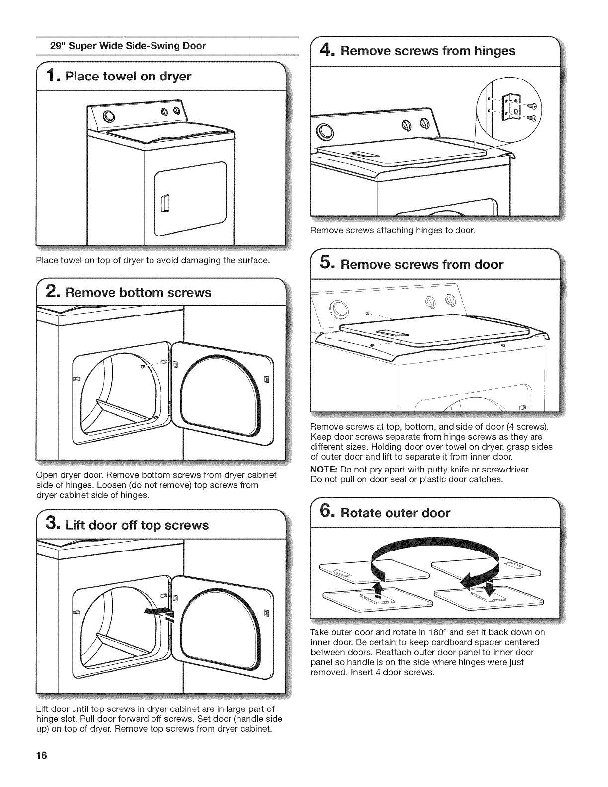
Flexible stainless steel gas connector:
[] If local codes permit, use a new flexible stainless steel gas
connector (Design Certified by the American Gas Association
or CSA International) to connect your dryer to the rigid gas
supply line. Use an elbow and a 3/8" flare x 3/8" NPT adapter
fitting between the stainless steel gas connector and the
dryer gas pipe, as needed to prevent kinking.
Option 2 (Alternate Method}
Approved aluminum or copper tubing:
[] Lengths over 20 ft. (6.1 m) can use 3/8" approved tubing
(if codes and gas supplier permit).
[] If you are using Natural Gas, do not use copper tubing.
[] 3/8" flare x 3/8" NPT adapter fitting between dryer pipe and
3/8" approved tubing.
[] Lengths over 20 ft. (6.1 m) should use larger tubing and a
different size adapter fitting.
[] If your dryer has been converted to use LP gas, 3/8" LP
compatible copper tubing can be used. If the total length
of the supply line is more than 20 ft. (6.1 m), use larger pipe.
NOTE: Pipe joint compounds that resist the action of LP
gas must be used. Do not use TEFLON _>ttape.
Dryer gas pipe
[] The gas pipe that comes out through the rear of your dryer
has a 3/8" male pipe thread.
29" Wide Model
27" Wide Model
A 9¼ "-_
(235 ram}
1¼"
(32 rnm}
A. 3/8" NPT dryer pipe
5 3/4"
(159 mm)
A
t 1/2"
(38 rnrn)
A. 3/8" NPT dryer pipe
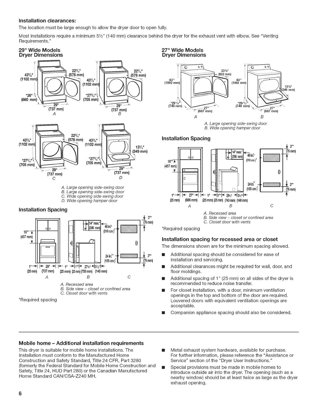
Burner input requirements
Elevations up to 10,000 ft. (3,048 m}:
[] The design of this dryer is certified by CSA international for
use at altitudes up to 10,000 ft. (3,048 m), above sea level at
the B.T.U. rating indicated on the model/serial number plate.
Burner input adjustments are not required when the dryer is
operated up to this elevation.
Elevations above 10,000 ft. (3,048 m}:
[] When installed above 10,000 ft. (3,048 m) a 4% reduction
of the burner B.T.U. rating shown on the model/serial
number plate is required for each 1,000 ft. (305 m)
increase in elevation.
Gas supply pressure testing
[] The dryer must be disconnected from the gas supply piping
system during pressure testing at pressures greater than
1/2 psi.
Electrica Requ
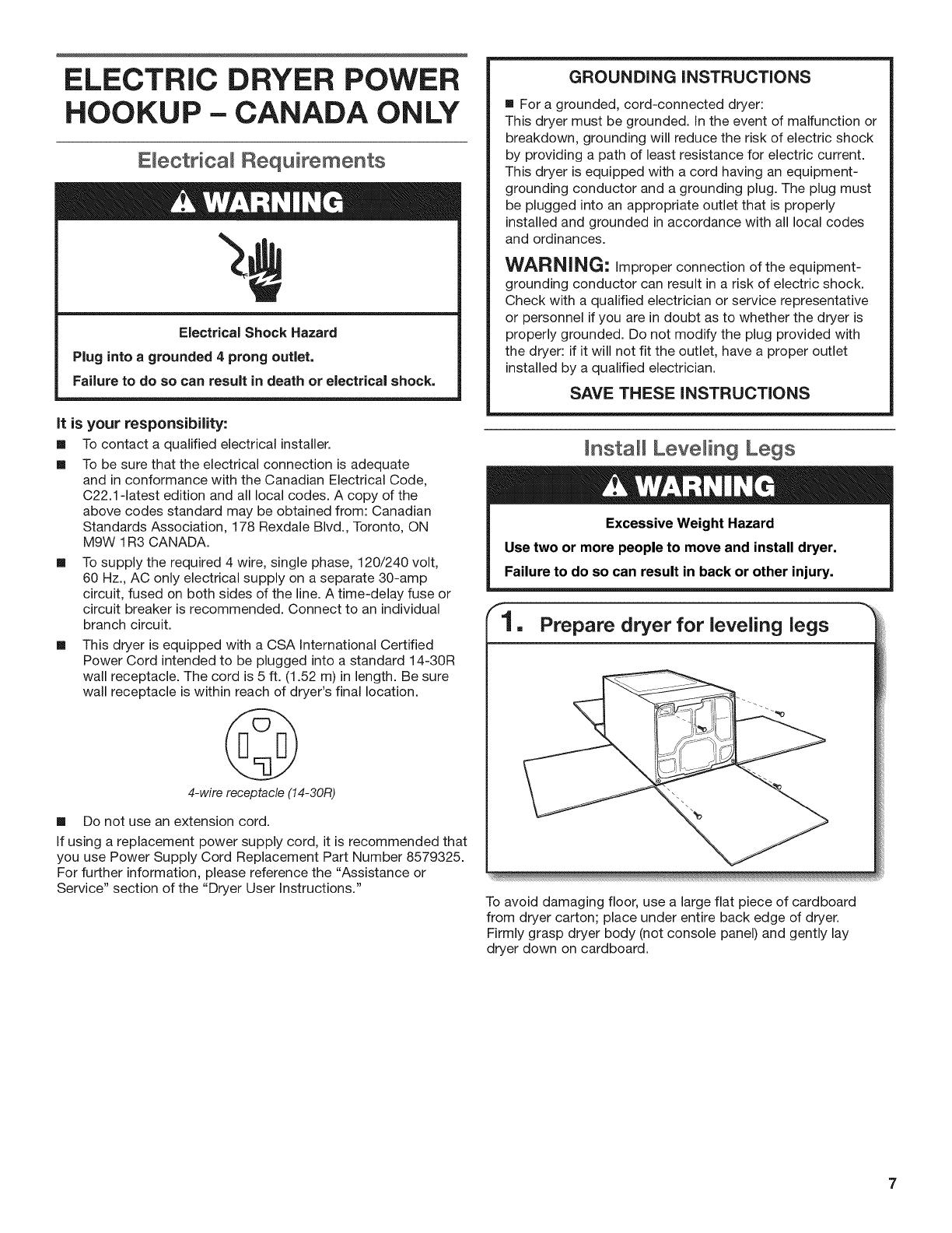
Electrical Shock Hazard
Plug into a grounded 3 prong outlet.
Do not remove ground prong.
Do not use an adapter,
Do not use an extension cord.
Failure to follow these instructions can result in death,
fire, or electrical shock.
[]
120 Volt, 60 Hz., AC only, 15- or 20-amp fused electrical
supply is required. A time-delay fuse or circuit breaker is
recommended, it is also recommended that a separate circuit
serving only this dryer be provided.
GROUNDING INSTRUCTIONS
[] For a grounded, cord-connected dryer:
This dryer must be grounded, in the event of malfunction or
breakdown, grounding will reduce the risk of electric shock
by providing a path of least resistance for electric current.
This dryer is equipped with a cord having an equipment-
grounding conductor and a grounding plug. The plug must
be plugged into an appropriate outlet that is properly
installed and grounded in accordance with all local codes
and ordinances.
WARNING: improper connection of the equipment-
grounding conductor can result in a risk of electric shock.
Check with a qualified electrician or service representative
or personnel if you are in doubt as to whether the dryer is
properly grounded. Do not modify the plug provided with
the dryer: if it will not fit the outlet, have a proper outlet
installed by a qualified electrician.
SAVE THESE INSTRUCTIONS
1-®)TEFLON is a registered trademark of E.I. Du Pont De Nemours and Company.
9