ProCom Heating CRHD18T User manual
- Category
- Fireplaces
- Type
- User manual

VENT-FREE GAS LOGS
OWNER’S OPERATION AND
INSTALLATION MANUAL
MODELS
CRHD18T AND CRHD24T
Questions, problems, missing parts? Before returning to your retailer, call
our customer service department at 1-866-573-0674, 7:30 am - 4:15 pm CST,
Monday through Friday or email customerservice@usaprocom.com
PFS
®
US
WARNING: If the information in this manual is not
followed exactly, a re or explosion may result causing
property damage, personal injury or loss of life.
— Do not store or use gasoline or other ammable va-
pors and liquids in the vicinity of this or any other
appliance.
— WHAT TO DO IF YOU SMELL GAS
• Do not try to light any appliance.
• Do not touch any electrical switch; do not use any
phone in your building.
•
Immediately call your gas supplier from a neighbor’s
phone. Follow the gas supplier’s instructions.
• If you cannot reach your gas supplier, call the re
department.
—
Installation and service must be performed by a quali-
ed installer, service agency or the gas supplier.
WARNING: This appliance is equipped for Natural and
Propane gas. Field conversion is not permitted other than
between natural or propane gases.
Cedar Ridge
hearth
®

www.usaprocom.com
200133-01B2
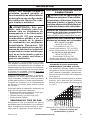
TABLE OF CONTENTS
Safety ........................................................ 3
Qualied Installing Agency ........................ 4
Specications ............................................ 5
Product Features ....................................... 5
Product Identication ................................. 5
Local Codes............................................... 6
Unpacking.................................................. 6
Water Vapor: A By-Product Of
Unvented Room Heaters ..................... 6
Air For Combustion and Ventilation ........... 7
Installation ................................................. 9
Operation ................................................. 20
Inspecting Burners................................... 22
Care And Maintenance ............................ 23
Troubleshooting ....................................... 24
Parts ........................................................ 28
Replacement Parts .................................. 30
Accessories ............................................. 30
Service Hints ........................................... 31
Technical Service..................................... 31
Warranty .................................................. 32
INSTALLER: Leave this manual with the appliance.
CONSUMER: Retain this manual for future reference.
This is an unvented gas-red heater. It uses air (oxygen)
from the room in which it is installed. Provisions for ad-
equate combustion and ventilation air must be provided.
Refer to Air For Combustion and Ventilation section on
page 7 of this manual.
WARNING: Improper installation, adjustment, al-
teration, service or maintenance can cause injury or
property damage. Refer to this manual for correct in-
stallation and operational procedures. For assistance
or additional information consult a qualied installer,
service agency or the gas supplier.
This appliance may be installed in an aftermarket,* per-
manently located, manufactured (mobile) home, where
not prohibited by local codes.
This appliance is only for use with propane or natural
gas. This appliance is equipped with a simple means to
switch between propane and natural gas. Field conver-
sion by any other means including the use of a kit is
not permitted.
* Aftermarket: Completion of sale, not for purpose of resale, from the manufacturer.
SAVE THIS BOOK

www.usaprocom.com
3200133-01B
SAFETY
IMPORTANT: Read this owner’s
manual carefully and completely
before trying to assemble, op-
erate, or service this heater.
Improper use of this heater can
cause serious injury or death
from burns, fire, explosion,
electrical shock and carbon
monoxide poisoning. Failure
to follow these instructions will
void the warranty.
Only a qualied installer, service
agent, or local gas supplier may
install and service this product.
WARNING: Keep the appli-
ance area clear and free from
combustible materials, gasoline,
and other ammable vapors and
liquids.
WARNING: This appliance
can be used with propane or
natural gas. It is shipped from
the factory adjusted for use with
propane.
DANGER: Carbon monoxide
poisoning may lead to death!
CARBON MONOXIDE POISONING: Early
signs of carbon monoxide poisoning resemble
the u, with headaches, dizziness or nausea.
If you have these signs, the heater may not be
working properly. Get fresh air at once! Have
heater serviced. Some people are more af-
fected by carbon monoxide than others. These
include pregnant women, people with heart or
lung disease or anemia, those under the inu-
ence of alcohol and those at high altitudes.
NATURAL AND PROPANE/LP GAS: Natural
and Propane/LP gas are odorless. An odor-
making agent is added to the gas. The odor
helps you detect a gas leak. However, the
odor added to the gas can fade. Gas may be
present even though no odor exists.
WARNING: Any change to
this heater or its controls can
be dangerous.
WARNING: Do not allow fans
to blow directly into replace.
Avoid any drafts that alter burner
ame patterns.
WARNING: Do not use a
blower insert, heat exchange
insert or other accessory not
approved for use with this heater.
WARNING: Due to high tem-
peratures, the appliance should
be located out of trafc and away
from furniture and draperies.
WARNING: Do not place
clothing or other flammable
material on or near the appli-
ance. Never place any objects
in the heater.
WARNING: The log set be-
comes very hot when running.
Keep children and adults away
from hot surfaces to avoid burns
or clothing ignition. Fireplace
will remain hot for a time after
shutdown. Allow surfaces to
cool before touching.
WARNING: Carefully super-
vise young children when they
are in the room with the heater.
WARNING: You must operate
this log set with screen in place.

www.usaprocom.com
200133-01B4
1. Do not place Propane/LP supply tank(s)
inside any structure. Propane/LP supply
tank(s) must be placed outdoors.
2. This heater shall not be installed in a
bedroom or bathroom.
3. This heater needs fresh air ventilation to
run properly. This heater has an Oxygen
Depletion Sensing (ODS) safety shutoff
system. The ODS shuts down the heater
if not enough fresh air is available. See
Air for Combustion and Ventilation, pages
7 and 8. If heater keeps shutting off, see
Troubleshooting, page 24.
4. Keep all air openings in front and bottom
of heater clear and free of debris. This will
ensure enough air for proper combustion.
5. If heater shuts off, do not relight until you
have provided fresh, outside air. If heater
keeps shutting off, have it serviced.
6. Do not run heater:
• Where ammable liquids or vapors are
used or stored.
• Under dusty conditions.
7. Before using furniture polish, wax, carpet
cleaner, or similar products, turn heater
off. If heated, the vapors from these prod-
ucts may create a white powder residue
within burner box or on adjacent walls or
furniture.
8. Do not use heater if any part has been
under water. Immediately call a qualied
service technician to inspect the room
heater and to replace any part of the
control system and any gas control which
has been under water.
9. Turn off heater and let cool before servic-
ing. Only a qualied service person should
service and repair heater.
SAFETY
10. Operating heater above elevations of
4,500 feet could cause pilot outage.
11. To prevent performance problems, do
not use propane/LP fuel tank of less than
100 lbs. capacity.
12. Do not use this heater as a wood-burning
heater. Use only the logs provided with the
heater.
13. Solid fuels should not be burned in
replace in which a vent-free log set is
installed. Do not use this heater to cook
food or burn paper or other objects.
14. To prevent sooting, follow the instructions
in Care and Maintenance (see page 23).
15. Do not add extra logs or ornaments such
as pine cones, vermiculite, or rock wool.
Using these added items can cause soot-
ing. Do not add lava rock around base.
Rock and debris could fall into the control
area of heater. After servicing, always
replace screen before operating heater.
16. This heater is designed to be smokeless. If
logs ever appear to smoke, turn off heater
and call a qualied service person.
Note: During initial operation, slight smok-
ing could occur due to log curing and the
heater burning manufacturing residues.
17. If replace has glass doors, never operate
this heater with glass doors closed. If you
operate heater with doors closed, heat will
build up inside replace and cause glass
to burst. If replace opening has vents
at the bottom, you must open the vents
before operating log set. Always operate
heater with glass doors fully open.
18. Do not use this heater if any log is broken.
Do not operate heater if a log is chipped
(dime-size or larger).
QUALIFIED INSTALLING AGENCY
Only a qualied agency should install and
replace gas piping, gas utilization equipment
or accessories, and repair and equipment ser-
vicing. The term “qualied agency” means any
individual, rm, corporation, or company that
either in person or through a representative
is engaged in and is responsible for:
a) Installing, testing, or replacing gas piping
or
b) Connecting, installing, testing, repairing,
or servicing equipment; that is experienced
in such work; that is familiar with all precau-
tions required; and that has complied with
all the requirement of the authority having
jurisdiction.

www.usaprocom.com
5200133-01B
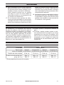
SPECIFICATIONS
Model CRHD18T Model CRHD24T
Ignition Electronic Piezo Ignitor
Gas Type Natural Gas Propane Gas Natural Gas Propane Gas
Input Rating
30,000 Btu/Hr 30,000 Btu/Hr 32,000 Btu/Hr 32,000 Btu/Hr
Manifold Pressure 4" W.C. 9" W.C. 4" W.C. 9" W.C.
Inlet Gas Pressure* (inches
of water) (*for purposes of
input adjustment)
Max. 9" Max. 14" Max. 9" Max. 14"
Min. 5" Min. 11" Min. 5" Min. 11"
PRODUCT FEATURES
This log set has been tested and approved to
ANSI Z21.11.2 standard for Unvented Heat-
ers and can be operated with the ue damper
closed. State and local codes in some areas
prohibit the use of vent-free heaters.
SAFETY PILOT
This heater has a pilot with an Oxygen Deple-
tion Sensing (ODS) safety shutoff system. The
ODS/pilot shuts off the heater if there is not
enough fresh air.
PIEZO IGNITION SYSTEM
This heater is equipped with an electronic
piezo control system. This system requires
AAA batteries (provided).
THERMOSTAT HEAT CONTROL
The control automatically cycles the burner
on and off to maintain a desired room
temperature.
2 GAS OPTIONS AVAILABLE
Your heater is equipped to operate on either
Propane/LP or Natural gas. The heater is
shipped from the factory ready for connect-
ing to Propane/LP. The heater can easily be
changed to Natural gas by having your quali-
ed installer follow the instructions on page
12 and the markings on the heater.
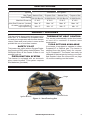
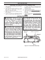
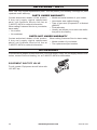
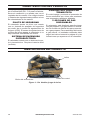
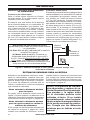
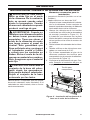
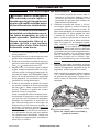
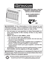
Figure 1 - Vent-Free Log Set
Logs
Ignitor Button
Control Knob
PRODUCT IDENTIFICATION

www.usaprocom.com
200133-01B6
WATER VAPOR: A BY-PRODUCT OF
UNVENTED ROOM HEATERS
Water vapor is a by-product of gas combus-
tion. An unvented room heater produces ap-
proximately one (1) ounce (30 mL) of water
for every 1,000 BTUs (0.3 KWs) of gas input
per hour. Unvented room heaters are recom-
mended as supplemental heat (a room) rather
than a primary heat source (an entire house).
In most supplemental heat applications, the
water vapor does not create a problem. In
most applications, the water vapor enhances
the low humidity atmosphere experienced
during cold weather.
The following steps will help ensure that water
vapor does not become a problem.
1. Be sure the heater is sized properly for the
application, including ample combustion
air and circulation air.
2. If high humidity is experienced, a dehu-
midier may be used to help lower the
water vapor content of the air.
3. Do not use an unvented room heater as
the primary heat source.
UNPACKING
1. Remove logs and burner base assembly
from carton.
Note: Do not pick up burner base as-
sembly by burners as this could damage
heater. Always handle base assembly by
grate.
2. Remove all protective packaging applied
to logs and heater for shipment.
3. Check all items for any shipping damage.
If damaged, promptly inform dealer where
you purchased the heater.
LOCAL CODES
Install and use heater with care. Follow all
local codes. In the absence of local codes,
use the latest edition of The National Fuel
Gas Code, ANSI Z223.1/NFPA 54*.
*Available from:
American National Standards Institute, Inc.
1430 Broadway
New York, NY 10018
National Fire Protection Association, Inc.
1 Batterymarch Park
Quincy, MA 02269-9101
This heater is designed for vent-free op-
eration. State and local codes in some areas
prohibit the use of vent-free heaters.
State of Massachusetts: The installation
must be made by a licensed plumber or
gas tter in the Commonwealth of Mas-
sachusetts.
Sellers of unvented propane or natural
gas-red supplemental room heaters shall
provide to each purchaser a copy of 527
CMR 30 upon sale of the unit.
In the State of Massachusetts the gas
cock must be a T-handle type. The State
of Massachusetts requires that a exible
appliance connector cannot exceed three
feet in length.

www.usaprocom.com
7200133-01B
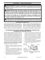
AIR FOR COMBUSTION AND VENTILATION
WARNING: This heater shall
not be installed in a conned space
or unusually tight construction
unless provisions are provided
for adequate combustion and
ventilation air. Read the following
instructions to insure proper fresh
air for this and other fuel-burning
appliances in your home.
Today’s homes are built more energy efcient
than ever. New materials, increased insulation
and new construction methods help reduce
heat loss in homes. Home owners weather
strip and caulk around windows and doors
to keep the cold air out and the warm air in.
During heating months, home owners want
their homes as airtight as possible.
While it is good to make your home energy
efcient, your home needs to breathe. Fresh
air must enter your home. All fuel-burning ap-
pliances need fresh air for proper combustion
and ventilation.
Exhaust fans, replaces, clothes dryers and
fuel burning appliances draw air from the house
to operate. You must provide adequate fresh
air for these appliances. This will insure proper
venting of vented fuel-burning appliances.
WARNING: This heater shall
not be installed in a room or
space unless the required vol-
ume of indoor combustion air
is provided by the method de-
scribed in the National Fuel Gas
Code, ANSI Z223.1/NFPA 54, the
International Fuel Gas Code, or
applicable local codes.
WARNING: If the area in which
the heater may be operated is
smaller than that dened as
an unconned space or if the
building is of unusually tight
construction, provide adequate
combustion and ventilation air
by one of the methods described
in the National Fuel Gas Code,
ANSI Z223.1/NFPA 54, the In-
ternational Fuel Gas Code, or
applicable local codes.

www.usaprocom.com
200133-01B8
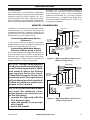
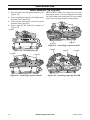
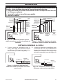
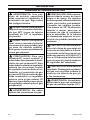
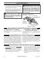
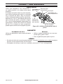
VENTILATION AIR
AIR FOR COMBUSTION AND VENTILATION
Outlet
Air
Ventilated
Attic
Outlet
Air
Inlet
Air
Inlet Air
Ventilated
Crawl Space
To
Crawl
Space
To Attic
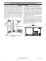
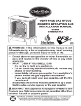
Figure 2 - Ventilation Air from Inside
Building
Figure 3 - Ventilation Air from Outdoors
Or
Remove
Door into
Adjoining
Room,
Option
3
Ventilation Grills
Into Adjoining Room,
Option 2
Ventilation
Grills Into
Adjoining
Room,
Option 1
12"
12"
Ventilation Air From Inside Building
This fresh air would come from an adjoining
unconned space. When ventilating to an
adjoining unconned space, you must provide
two permanent openings: one within 12" of the
ceiling and one within 12" of the oor on the
wall connecting the two spaces (see options
1 and 2, Figure 2). You can also remove door
into adjoining room (see option 3, Figure 2).
Follow the National Fuel Gas Code, ANSI
Z223.1/NFPA 54, Air for Combustion and
Ventilation for required size of ventilation
grills or ducts.
Ventilation Air From Outdoors
Provide extra fresh air by using ventilation
grills or ducts. You must provide two perma-
nent openings: one within 12" of the ceiling
and one within 12" of the oor. Connect these
items directly to the outdoors or spaces open
to the outdoors. These spaces include attics
and crawl spaces. Follow the National Fuel
Gas Code, ANSI Z223.1/NFPA 54, Air for
Combustion and Ventilation for required size
of ventilation grills or ducts.
IMPORTANT: Do not provide openings
for inlet or outlet air into attic if attic has a
thermostat-controlled power vent. Heated air
entering the attic will activate the power vent.
Rework worksheet, adding the space of the
adjoining unconned space. The combined
spaces must have enough fresh air to supply
all appliances in both spaces.

www.usaprocom.com
9200133-01B
INSTALLATION
NOTICE: This heater is intended
for use as supplemental heat.
Use this heater along with your
primary heating system. Do not
install this heater as your pri-
mary heat source. If you have a
central heating system, you may
run system’s circulating blower
while using heater. This will help
circulate the heat throughout the
house. In the event of a power
outage, you can use this heater
as your primary heat source.
WARNING: A qualied ser-
vice person must install heater.
Follow all local codes.
WARNING: Before installing
in a solid fuel burning replace,
the chimney ue and rebox
must be cleaned of soot, creo-
sote, ashes and loose paint by
a qualified chimney cleaner.
Creosote will ignite if highly
heated. A dirty chimney ue may
create and distribute soot within
the house. Inspect chimney ue
and rebox for damage. If dam-
aged, repair ue before operat-
ing heater.
WARNING: Seal any fresh
air vents or ash clean-out doors
located on oor or wall of re-
place. If not, drafting may cause
pilot outage or sooting. Use a
heat-resistant sealant. Do not
seal chimney ue damper.
WARNING: Never install the
heater
• in a bedroom or bathroom
• in a recreational vehicle
• where curtains, furniture, cloth-
ing, or other ammable objects
are less than 36" from the front,
42" from top, or 16" from sides
of the heater.
• in high trafc areas
• in windy or drafty areas
CAUTION: This heater cre-
ates warm air currents. These
currents move heat to wall sur-
faces next to heater. Installing
heater next to vinyl or cloth wall
coverings or operating heater
where impurities (such as to-
bacco smoke, aromatic candles,
cleaning uids, oil or kerosene
lamps, etc.) in the air exist, may
discolor walls or cause odors.
NOTICE: State or local codes
may only allow operation of this
appliance in a vented congura-
tion. Check your state or local
codes.
WARNING: This appliance is
designed for installation in only
a solid-fuel burning masonry or
UL 127 factory-built replace or
in a listed ventless rebox enclo-
sure. Exception: DO NOT install
this appliance in a factory-built
replace that includes instruc-
tions stating it has not been
tested or should not be used
with unvented gas logs.

www.usaprocom.com
200133-01B10
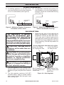
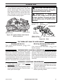
Figure 4 - Minimum Clearance for
Combustible to Wall
INSTALLATION
IMPORTANT: Vent-free heaters add moisture
to the air. Although this is benecial, installing
heater in rooms without enough ventilation air
may cause mildew to form too much moisture.
See Air for Combustion and Ventilation, pages
7 and 8.
Before beginning assembly or operation of the
product, make sure all parts are present. If any
part is missing or damaged, do not attempt to
assemble, install or operate the product. Con-
tact customer service for replacement parts.
Before installing heater, make sure you have
the items listed below:
• Hardware package (provided with heater)
• Electric drill with 3/16" drill bit
• Phillips screwdriver
CHECK GAS TYPE
Be sure your gas supply is right for your heat-
er. Otherwise, call dealer where you bought
the heater for proper type heater.
CLEARANCES TO
COMBUSTIBLES
WARNING: Maintain the
minimum clearances. If possible,
provide greater clearances from
oor, ceiling, and adjoining wall.
Measure from outermost point
of heater.
Minimum Fireplace Clearance To
Combustible Materials
Side Wall 16", Ceiling 42", Front 36"
LOG SIZING REQUIREMENTS
Minimum Firebox Size
18" Log Set: Height 20", Depth 13",
Front Width 29", Rear Width 22"
24" Log Set: Height 20", Depth 14",
Front Width 30", Rear Width 23"
Minimum Clearances For Side
Combustible Material, Side Wall
and Ceiling
A. Clearance from the side of the replace
cabinet to any combustible material and
wall should follow diagram in Figure 4.
B. Clearance from the top of the replace
opening to the ceiling must not be less
than 42".
Minimum Noncombustible Material
Clearances
If Not Using Mantel
Note: If using a mantel, proceed to If Using
Mantel. If not using a mantel, follow the infor-
mation below.
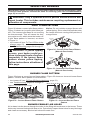
You must have noncombustible material(s)
above the replace opening. Noncombustible
materials (such as slate, marble, tile, etc.)
must be at least 1/2" thick. With sheet metal,
you must have noncombustible material be-
hind it. Noncombustible material must extend
at least 12" up (for all models). See Figure 5
for minimum clearances.
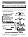
*Minimum 16" from Side Wall
*
Figure 5 - Heat Resistant Material (Slate,
Marble, Tile, etc.) Above Fireplace
Noncombustible
Material Distance
Requirements for Safe Installation
(A) 12" or more: Noncombustible
material OK.
(A) Between 8" and 12":
Install replace hood accessory.
(A) Less than 8": Noncombustible
material must be extended to at least 8".
See Between 8" and 12", above. If you
cannot extend material, you must operate
heater with ue damper open.

www.usaprocom.com
11200133-01B
INSTALLATION
at least 8" up. If noncombustible material is
less than 12", you must install the replace
hood accessory. Even if noncombustible
material is more than 12", you may need the
hood accessory to deect heat away from
your mantel shelf. See Figures 5, 6 and 7, for
minimum clearances.
Figure 6 - Minimum Mantel Clearances
Without Using Hood
Figure 7 - Minimum Mantel Clearances
When Using Hood
If Using Mantel
You must have noncombustible material(s)
above the replace opening. Noncombustible
materials (such as slate, marble, tile, etc.)
must be at least 1/2" thick. With sheet metal,
you must have noncombustible material be-
hind it. Noncombustible material must extend
Minimum
Noncombustible
Material
Minimum
Noncombustible
Material Height
Distances to
Underside of
Mantel
Top of
Fireplace
Opening
Underside of
Mantel Shelf
Mantel Shelf
8"
(A)
8" 14" 16" 20"
18" Log Set
12" 18" 20" 22" 24" 24" Log Set
All minimum
distances are
in inches
2
1
/
2
"
6"
8"
10"
Minimum
Noncombustible
Material
8"
Min.
12" 15" 18" 20"
2½"
6"
8"
10"
12"
Distances to
Underside of
Mantel
Hood
Top of
Fireplace
Opening
Underside
of Mantel
Shelf
Mantel Shelf
MANTEL CLEARANCES
In addition to meeting noncombustible mate-
rial clearances, you must also meet required
clearances between replace opening and
mantel shelf. If you do not meet the clearances
listed below, you will need a hood.
Determining Minimum Mantel
Clearance
If you meet minimum clearance between
mantel shelf and top of replace opening, a
hood is not required (see Figure 6).
Determining Minimum Mantel
Clearance When Using a Hood
If minimum clearances in Figure 6 are not met,
you must have a hood. When using a hood
there are still certain minimum mantel clear-
ances required. Follow minimum clearances
shown in Figure 7, when using hood.
NOTICE: Surface temperatures
of adjacent walls and mantels be-
come hot during operation. Walls
and mantels above the rebox
may become hot to the touch.
If installed properly, these tem-
peratures meet the requirement
of the national product standard.
Follow all minimum clearances
shown in this manual.
NOTICE: If your installation does
not meet the minimum clear-
ances shown, you must do one
of the following:
• operate the logs only with the
ue damper open
• raise the mantel to an accept-
able height
• move the mantel

www.usaprocom.com
200133-01B12
INSTALLATION
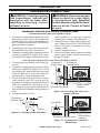
FLOOR CLEARANCES
Hearth
5"
Min.
Combustible
Material
14"
Min.
Combustible
Material
Noncombustible Material
Figure 8 - Minimum Fireplace Clearances
If Installed at Floor Level
Figure 9 - Minimum Fireplace Clearances
Above Combustible Flooring
A. If installing appliance on the oor level,
you must maintain the minimum distance
of 14" to combustibles (see Figure 8).
B. If combustible materials are less than 14"
to the replace, you must install appliance
at least 5" above the combustible ooring
(see Figure 9).
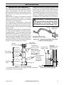
Yellow Natural Gas
Plunger Underneath
Metal Plug
Blue Propane/LP Gas
Plunger Underneath
Dust Cover
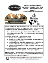
Figure 10 - Gas Regulator
Insert Gas Fitting
for Natural Gas
Access Regulator from Back of Log Set
Insert Gas Fitting
for Propane/LP Gas
GAS SELECTION
This appliance is factory
preset for propane/LP gas.
No changes are required for
connecting to propane/LP.
Only a qualied installer or service
technician can perform gas selec-
tion and connecting to gas supply.
CAUTION: Two gas line in-
stallations at the same time are
prohibited.
CAUTION: To avoid gas leak-
age for the gas not being used at
the inlet of regulator, a qualied
installer or service technician
must use supplied plug.
WARNING: Do not attempt to
access or change the setting of
the fuel selection means.
1. The inlet regulator is color coded for iden-
tication of the correct gas type. Blue is for
propane (LP gas) and yellow is for natural
gas.
2. The inlet regulator requires a 3/8" NPT
threaded tting. Apply a thread sealant
that is rated for use with the type of gas
that is being used.
3. Determine the type of gas that will be
used by the appliance. If your gas type is
Propane/LP remove the blue dust cover.
If your gas type is Natural gas remove
metal plug from natural gas inlet. Remove
blue dust cover from propane/LP inlet and
install metal plug. This will keep debris out
of regulator.

www.usaprocom.com
13200133-01B
INSTALLATION
Figure 11 - Attaching Heater Base to
Fireplace Floor
Masonry
Screw
INSTALLING HEATER BASE ASSEMBLY
Installation Items Needed
• hardware package (provided with heater)
• electric drill with 3/16" masonry drill bit
1. Position heater base assembly in re-
place. Center base assembly left to right
and front to back inside replace.
2. Mark screw locations through holes in
mounting brackets (see Figure 11). If
installing in a brick-bottom replace, mark
screw locations in mortar joint of bricks.
3. Remove heater base from replace.
4. Drill holes at marked locations using 3/16"
drill bit.
5. Attach base assembly to replace oor
using two masonry screws provided in
hardware package (see Figure 11).
6. Connect to gas supply. See Connecting
To Gas Supply, page 14.
WARNING: You must secure
this heater to replace oor. If
not, heater will move when you
adjust controls. Moving heater
may cause a gas leak.
WARNING: If installing in a
sunken replace, special care
is needed. You must raise the
replace oor to allow access to
heater control panel. This will in-
sure adequate air ow and guard
against sooting and controls
being damaged. Raise replace
oor with noncombustible mate-
rial. Make sure material is secure.
CAUTION: Do not pick up
heater base assembly by burners.
This could damage heater. Only
handle base assembly by grates.
IMPORTANT: Make sure the heater burners
are level. If heater is not level, heater will not
work properly.
Make sure the type of gas being
used is correct. Check to make
sure the connection tting is in
the correct inlet on the regula-
tor. Refer to Connecting to Gas
Supply, page 14.
If you are using natural gas
and the pilot will not light, see
Troubleshooting, page 24.
Note: After the outside plug on the bottom
of the regulator has been removed, you will
notice a color coded plunger on the inside of
the regulator. This is normal. When the inlet
connection tting is inserted and tightened,
this plunger will be pushed back by the t-
ting making all of the adjustments to the gas
being supplied.
4. Apply thread sealant to the threads on
the connection tting. While pushing in,
rotate the tting clockwise until the threads
engage the regulator. After the tting has
been hand tightened into the regulator
use a wrench to complete tightening of
the tting.

www.usaprocom.com
200133-01B14
INSTALLATION
CONNECTING TO GAS SUPPLY
CAUTION: For natural gas,
check your gas line pressure
before connecting heater to gas
line. Gas line pressure must be
no greater than 9" WC. If gas line
pressure is higher, heater regula-
tor damage could occur.
CAUTION: Avoid damage to
regulator. Hold gas regulator
with wrench when connecting
into gas piping and/or ttings.
CAUTION: Use pipe joint
sealant that is resistant to gas
(Propane/LP or Natural Gas).
Before installing heater, make sure you have
the items listed below:
• external regulator for propane/LP unit only
(supplied by installer)
• piping (check local codes)
• sealant (resistant to natural gas and pro-
pane/LP gas)
• equipment shutoff valve*
• test gauge connection*
• sediment trap
• tee joint
• pipe wrench
• exible gas hose (check local codes)
* A CSA design-certied equipment shutoff
valve with 1/8" NPT tap is an acceptable al-
ternative to test gauge connection. Purchase
the optional CSA design certied equipment
shutoff valve from your dealer.
WARNING: A qualied ser-
vice technician must connect
heater to gas supply. Follow all
local codes.
WARNING: This appliance
requires a 3/8" NPT (National
Pipe Thread) inlet connection to
the pressure regulator.
WARNING: For natural gas,
Never connect heater to private
(non-utility) gas wells. This gas
is commonly known as wellhead
gas.
CAUTION: For propane/LP
gas, never connect heater direct-
ly to the gas supply. This heater
requires an external regulator
(not supplied). Install the external
regulator between the heater and
propane/LP supply. Gas supplier
provides external regulator for
natural gas. The installer pro-
vides the external regulator for
propane/LP gas.
WARNING: Do not over-
tighten gas connections.
CAUTION: Use only new,
black iron or steel pipe. Inter-
nally tinned copper tubing may
be used in certain areas. Check
your local codes. Use pipe of
1/2" diameter or greater to allow
proper gas volume to heater. If
pipe is too small, undue loss of
pressure will occur.

www.usaprocom.com
15200133-01B
INSTALLATION
Figure 13 - Gas Connection
Figure 12 - Attaching Flexible Gas Hose
to Heater Gas Regulator
* Purchase the optional CSA design-certied equipment
shutoff valve from your dealer.
Typical Inlet Pipe Diameters
Use 3/8" black iron pipe or greater. Installa-
tion must include an equipment shutoff valve,
union, and plugged 1/8" NPT tap. Locate
NPT tap within reach for test gauge hook up.
NPT tap must be upstream from heater (see
Figure 13).
IMPORTANT: Install an equipment shutoff
valve in an accessible location. The equip-
ment shutoff valve is for turning on or shutting
off the gas to the appliance.
For propane/LP installations, apply pipe
joint sealant lightly to male threads. This will
prevent excess sealant from going into pipe.
Excess sealant in pipe could result in clogged
heater valves.
The installer must supply an external regula-
tor. The external regulator will reduce incom-
ing gas pressure. You must reduce incoming
gas pressure to between 11" WC and 14" WC.
If you do not reduce incoming gas pressure,
heater regulator damage could occur. Install
external regulator with the vent pointing down
as shown in Figure 14. Pointing the vent down
protects it from freezing rain or sleet.
Figure 14 - External Regulator
with Vent Pointing Down
External
Regulator with
Vent Pointing
Down
Propane/LP
Supply Tank
Equipment
Shutoff Valve
Ground
Joint Union
3/8" NPT
Pipe Nipple
Flexible Gas Hose (if
allowed by local codes)
Fitting
Heater Gas
Regulator
Tee Joint
Reducer
Bushing to
1/8" NPT
1/8" NPT
Plug Tap
Test Gauge
Connection*
Sediment
Trap
Tee Joint
Pipe Nipple
Gap
3" Minimum
Install sediment trap in supply line as shown
in Figure 13. Place sediment trap where it is
within reach for cleaning. Place sediment trap
where trapped matter is not likely to freeze.
A sediment trap traps moisture and contami-
nants. This keeps them from going into heater
controls. If sediment trap is not installed or is
installed wrong, heater may not run properly.
WARNING: Test all gas piping
and connections for leaks after
installing or servicing. Correct
all leaks at once (see page 16).
Natural Gas
From Gas Meter
(5" W.C.** to 9"
W.C. Pressure)
Propane/LP
From External
Regulator
(11" W.C.**
to 14" W.C.
Pressure)

www.usaprocom.com
200133-01B16
INSTALLATION
Figure 15 - Equipment Shutoff Valve
CHECKING GAS CONNECTIONS
Open
Closed
Equipment
Shutoff Valve
WARNING: Never use an open
ame to check for a leak. Apply
a noncorrosive leak detection
uid to all joints. If bubbles form,
there is a leak. Correct all leaks
at once.
Control Valve
Location
Control Valve
Location
Equipment
Shutoff Valve
Equipment Shutoff Valve
External Regulator
Propane/LP
Supply Tank
Figure 16 - Checking Gas Joints for
Propane/LP Gas
Figure 17 - Checking Gas Joints for
Natural Gas
Gas Meter
WARNING: Test all gas piping
and connections, internal and
external to unit, for leaks after
installing or servicing. Correct
all leaks at once.
PRESSURE TESTING GAS SUPPLY PIPING SYSTEM
Test Pressures In Excess Of 1/2 PSIG (3.5 kPa)
1. Disconnect heater with its appliance main
gas valve (control valve) and equipment
shutoff valve from gas supply piping sys-
tem. Pressures in excess of 1/2 PSIG will
damage heater regulator.
2. Cap off open end of gas pipe where equip-
ment shutoff valve was connected.
3. Pressurize supply piping system by either
opening propane/LP supply tank valve
for propane/LP gas or opening main gas
valve located on or near gas meter for
natural gas or using compressed air.
4. Check all joints of gas supply piping sys-
tem. Apply noncorrosive leak detection
uid to all joints. If bubbles form, there
may be a leak.
5. Correct all leaks at once.
6. Reconnect heater and equipment shutoff
valve to gas supply. Check reconnected
ttings for leaks.
Test Pressures Equal To or Less Than 1/2 PSIG (3.5 kPa)
1. Close equipment shutoff valve (see Fig-
ure 15).
2. Pressurize supply piping system by either
opening propane/LP supply tank valve
for propane/LP gas or opening main gas
valve located on or near gas meter for
natural gas or using compressed air.
3. Check all joints from gas meter to equip-
ment shutoff valve for natural gas or
propane/LP supply to equipment shutoff
valve for propane/LP (see Figure 16 or
17). Apply a noncorrosive leak detection
uid to all joints. Bubbles forming show a
leak.
4. Correct all leaks at once.

www.usaprocom.com
17200133-01B
INSTALLATION
PRESSURE TESTING HEATER GAS CONNECTIONS
1. Open equipment shutoff valve (see Figure
15, page 16).
2. Open main gas valve located on or near
gas meter for natural gas or open pro-
pane/LP supply tank valve.
3. Make sure control knob of heater is in the
OFF position.
4. Check all joints from equipment shutoff
valve to control valve (see Figure 16 or
17, page 16). Apply a noncorrosive leak
detection uid to all joints. Bubbles form-
ing show a leak.
5. Correct all leaks at once.
6. Light heater (see Lighting Instructions on
page 20). Check all other internal joints
for leaks.
7. Turn off heater (see To Turn Off Gas Ap-
pliance, page 21).
WARNING: Failure to posi-
tion the parts in accordance
with these diagrams or failure
to use only parts specically
approved with this heater may
result in property damage or
personal injury.
CAUTION: After installation,
and periodically thereafter,
check to ensure that no ame
comes in contact with any log.
With the heater set to high, check
to see if ames contact any log. If
so, reposition logs according to
the log installation instructions
in this manual. Flames contact-
ing logs will create soot.
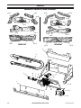
INSTALLING LOGS
Rear Log
Bracket
Middle Log Bracket
Front Log
Bracket
Grate
Figure 18 - Heater Base Assembly
It is very important to install the
logs exactly as instructed. Do
not modify logs. Use only logs
supplied with heater. Each log
is marked with a number. This
number will help you to identify
the logs when installing. After
installing logs, add decorative
cinders around the grate base,
do not place any decorative
cinders on logs or burner.

www.usaprocom.com
200133-01B18
INSTALLATION
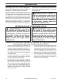
Log #2
Log #6
Log #7
Log #8
Log #4
Log #5
Log #3
Figure 20 - Installing Logs #2 and #3
Figure 21 - Installing Logs #4 and #5
Figure 22 - Installing Logs #6, #7 & #8
Model CRHD18T (18" Log Set)
Log #1
Figure 19 - Installing Log #1
1. Place log #1 onto rear grate bracket (see
Figure 19).
2. Place log #2 and log #3 onto middle grate
bracket (see Figure 20).
3. Place log #4 and log #5 onto front grate
bracket (see Figure 21).
4. Place logs #6, #7 and #8 as shown in
Figure 22.
IMPORTANT: Make sure logs do not cover
any burner ports. It is very important to install
the logs exactly as instructed. Do not modify
logs. Use only logs supplied with heater.

www.usaprocom.com
19200133-01B
INSTALLATION
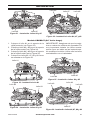
Log #2
Log #6
Log #7
Log #8
Log #9
Log #4
Log #5
Log #3
Figure 24 - Installing Logs #2 and #3
Figure 25 - Installing Logs #4 and #5
Figure 23 - Installing Log #1
Figure 26 - Installing Logs #6, #7, #8 & #9
Model CRHD24T (24" Log Set)
1. Place log #1 onto rear grate bracket (see
Figure 23).
2. Place log #2 and log #3 onto middle grate
bracket (see Figure 24).
3. Place log #4 and log #5 onto front grate
bracket (see Figure 25).
4. Place logs #6, #7, #8 and #9 as shown in
Figure 26.
Log #1
IMPORTANT: Make sure logs do not cover
any burner ports. It is very important to install
the logs exactly as instructed. Do not modify
logs. Use only logs supplied with heater.
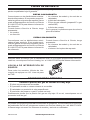
Battery Instructions
CAUTION: Do not mix old and
new batteries. Do not mix alka-
line, standard (carbon - zinc), or
rechargeable (nickel - cadmium)
batteries. Do not dispose of
batteries in re, batteries may
explode or leak.
• Batteries are included.
• Remove batteries when depleted.
• Install/replace the batteries according to the
type and quantity stated in table to the right.
• Do not mix old and new batteries. New bat-
teries should be the same brand for best
results.
• Be sure to observe proper polarity (+/-)
when installing or replacing the batteries.
Damage due to improper battery installation
may void the warranty on the product.
• For long periods of non-operation, remove
batteries from all components for safety.
Figure 27 - Installing Battery in Ignitor
AAA
Battery
Positive
UP

www.usaprocom.com
200133-01B20
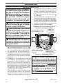
OPERATION
FOR YOUR SAFETY READ BEFORE LIGHTING
WARNING: If you do not fol-
low these instructions exactly, a
re or explosion may result caus-
ing property damage, personal
injury or loss of life.
A. This appliance has a pilot which must
be lighted by hand. When lighting the
pilot, follow these instructions exactly.
B. BEFORE LIGHTING smell all around
the appliance area for gas. Be sure to
smell next to the oor because some
gas is heavier than air and will settle
on the oor.
WHAT TO DO IF YOU SMELL GAS
• Do not try to light any appliance.
• Do not touch any electric switch; do
not use any phone in your building.
• Immediately call your gas supplier
from a neighbor’s phone. Follow the
gas supplier’s instructions.
• If you cannot reach your gas supplier,
call the re department.
C. Use only your hand to push in or turn
the gas control knob. Never use tools.
If the knob will not push in or turn
by hand, don’t try to repair it, call a
qualied service technician. Force or
attempted repair may result in a re or
explosion.
D. Do not use this appliance if any part
has been under water. Immediately call
a qualied service technician to inspect
the appliance and to replace any part of
the control system and any gas control
which has been under water.
WARNING: You must oper-
ate this heater with the screen
in place. Make sure screen is
installed before running heater.
NOTICE: During initial operation
of new heater, burning logs will
give off a paper-burning smell.
Orange ame will also be pres-
ent. Open damper or window to
vent smell. This will only last a
few hours.
1. STOP! Read the safety information above.
2. Make sure equipment shutoff valve is fully
open.
3. Push in control knob slightly and turn
clockwise to the OFF position.
4. Wait ve (5) minutes to clear out any gas.
Then smell for gas around heater and near
the oor. If you smell gas, STOP! Follow
"B" in the safety information above. If you
do not smell gas, go to the next step.
5. Push in control knob slightly and turn coun-
terclockwise to the PILOT position.
Press in control knob for ve (5) seconds.
Note: The rst time that the heater is oper-
ated after connecting the gas supply, the
control knob should be pressed for about
thirty (30) seconds. This will allow air to
bleed from the gas system. If pilot does not
stay lit, refer to Troubleshooting, pages 24
though 27. Also contact a qualied service
technician or gas supplier for repairs. Until
repairs are made, light pilot with match.
• If control knob does not pop up when
released, contact a qualified service
technician or gas supplier for repairs.
6. With control knob pressed in, push
down and release ignitor button. This
will light pilot. The pilot is attached to
the rear of the burner. If needed, keep
pressing ignitor button until pilot lights.
Note: If pilot does not stay lit, refer to
Troubleshooting, pages 24 though 27.
Also contact a qualied service technician
or gas supplier for repairs. Until repairs are
made, light pilot with match. To light pilot
with match, see Manual Lighting Procedure,
page 21.
7. Keep control knob pressed in for 30 sec-
onds after lighting pilot. After 30 seconds,
release control knob.
Note: If pilot goes out, repeat steps 3
through 7. This heater has a safety inter-
lock system. Wait one (1) minute before
lighting pilot again.
LIGHTING INSTRUCTIONS
Page is loading ...
Page is loading ...
Page is loading ...
Page is loading ...
Page is loading ...
Page is loading ...
Page is loading ...
Page is loading ...
Page is loading ...
Page is loading ...
Page is loading ...
Page is loading ...
Page is loading ...
Page is loading ...
Page is loading ...
Page is loading ...
Page is loading ...
Page is loading ...
Page is loading ...
Page is loading ...
Page is loading ...
Page is loading ...
Page is loading ...
Page is loading ...
Page is loading ...
Page is loading ...
Page is loading ...
Page is loading ...
Page is loading ...
Page is loading ...
Page is loading ...
Page is loading ...
Page is loading ...
Page is loading ...
Page is loading ...
Page is loading ...
Page is loading ...
Page is loading ...
Page is loading ...
Page is loading ...
Page is loading ...
Page is loading ...
Page is loading ...
Page is loading ...
Page is loading ...
Page is loading ...
Page is loading ...
Page is loading ...
-
 1
1
-
 2
2
-
 3
3
-
 4
4
-
 5
5
-
 6
6
-
 7
7
-
 8
8
-
 9
9
-
 10
10
-
 11
11
-
 12
12
-
 13
13
-
 14
14
-
 15
15
-
 16
16
-
 17
17
-
 18
18
-
 19
19
-
 20
20
-
 21
21
-
 22
22
-
 23
23
-
 24
24
-
 25
25
-
 26
26
-
 27
27
-
 28
28
-
 29
29
-
 30
30
-
 31
31
-
 32
32
-
 33
33
-
 34
34
-
 35
35
-
 36
36
-
 37
37
-
 38
38
-
 39
39
-
 40
40
-
 41
41
-
 42
42
-
 43
43
-
 44
44
-
 45
45
-
 46
46
-
 47
47
-
 48
48
-
 49
49
-
 50
50
-
 51
51
-
 52
52
-
 53
53
-
 54
54
-
 55
55
-
 56
56
-
 57
57
-
 58
58
-
 59
59
-
 60
60
-
 61
61
-
 62
62
-
 63
63
-
 64
64
-
 65
65
-
 66
66
-
 67
67
-
 68
68


ProCom Heating CRHD18T User manual
- Category
- Fireplaces
- Type
- User manual
Ask a question and I''ll find the answer in the document
Finding information in a document is now easier with AI
in other languages
Related papers
-
 ProCom Heating CRHD18T User manual
-
 ProCom Heating CRHD18T User manual
-
ProCom Heating 170092 User manual
-
 ProCom Heating PCD18T User manual
-
 ProCom Heating PCILVFD18T-2 User manual
-
Lost River PCILVFD24H-2 Installation guide
-
 ProCom Heating CRHEB24RTA User manual
-
 ProCom Heating MNSD300TGA User manual
-
 ProCom Heating CRHSD25RTA User manual
-
 ProCom Heating CRHED24RT User manual


Other documents
-
 Cedar Ridge CRHD18T Owner's Operation And Installation Manual
-
Procom 170097 User manual
-
-
Superior FVFM27NR Installation And Operation Instructions Manual
-
FMI CSG3924NRB Owner's manual
-
Comfort Flame CSG3924NRC User manual
-
-
-
FMI CF2436PR-M User manual
-
FMI EWPO2430NV User manual
