
24/7 TECHNICAL SUPPORT AT 1.877.877.2269 OR VISIT BLACKBOX.COM
WEB GUI USER MANUAL
INDUSTRIAL
MANAGED
SWITCH
LIG1014A, LIG1080A, LIG1082A, LIE1014A, LIE1080A, LIE1082A
P1 P2 ALM
13
P1 P2 ALM P1
POE P2 ALM
8
7
RR
RS
12
4
6
8
10
12
14
3
5
7
1 2
4
3
5
7
9
11
6
8
5
3
1
1
2
3
4
2
4
6

LOREM IPSUM
21. 8 7 7. 8 7 7. 2 2 6 9 BLACKBOX.COM
CONTENTS
CONTENTS.......................................................................................................................................................................................2
1. OVERVIEW................................................................................................................................................................................3–4
1.1 SYSTEM DESCRIPTION........................................................................................................................................................3
1.2 USING THE WEB INTERFACE.........................................................................................................................................3–4
1.3 USING THE ONLINE HELP....................................................................................................................................................4
2. USING THE WEB..................................................................................................................................................................5–245
2.1 LOGIN.......................................................................................................................................................................................5
2.2 TREE VIEW.........................................................................................................................................................................5–6
2.3 CONFIGURATION..........................................................................................................................................................7–163
2.4 MONITOR...................................................................................................................................................................164–237
2.5 DIAGNOSTICS...........................................................................................................................................................237–241
2.6 MAINTENANCE........................................................................................................................................................242–245

1. OVERVIEW
1.1 SYSTEM DESCRIPTION
The Industrial Managed Gigabit Ethernet Switch delivers high-quality, wide-operating temperature range, extended power input
range, IP-30 design, and advanced VLAN and QoS features. It’s ideal for harsh environments and mission critical applications.
Managed QoS LIG1014A/LIE1014A provides enterprise-class networking features to fulfill the needs of large network
infrastructure and extreme environments.
LIG1014A/LIE1014A eases the effort to build a network infrastructure that offers reliable, well managed, and good QoS
networking for any business requiring continuous and well-protected services in managed environments. With features
such as Fast Failover ring protection and QoS, customers can ensure their network will support real-time and
high-quality applications.
1.2 USING THE WEB INTERFACE
This document describes the switch’s web management feature and design layout, and explains how to use the
web interface.
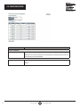
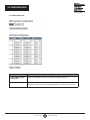
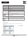
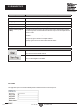
1.2.1 WEB BROWSER SUPPORT
IE 7 (or newer version) with the following default settings is recommended:
Language script Latin based
Web page font Times New Roman
Plain text font Courier New
Encoding Unicode (UTF-8)
Tex t size Medium
Firefox with the following default settings is recommended:
Web page font Times New Roman
Encoding Unicode (UTF-8)
Tex t size 16
Google Chrome with the following default settings is recommended:
Web page font Times New Roman
Encoding Unicode (UTF-8)
Tex t size Medium
1.2.2 NAVIGATION
31. 8 7 7. 8 7 7. 2 2 6 9 BLACKBOX.COM
1. OVERVIEW / 1.1 SYSTEM DESCRIPTION / 1.2 USING THE WEB INTERFACE

41. 8 7 7. 8 7 7. 2 2 6 9 BLACKBOX.COM
You can reach all main screens of the web interface by clicking on hyperlinks in the four menu boxes
on the left side of the screen:
• CONFIGURATION
• MONITOR
• DIAGNOSTICS
• MAINTENANCE
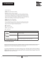
1.2.3 TITLE BAR ICONS
Help Button
For more information about any screen, click on the ‘Help’ button on the screen. Help information is
displayed in the same window.
Save Button
If any unsaved change has been made to the configuration (by you or any other administrator
using the web interface or the Command Line Interface during this or a prior session), a ‘Save’ icon
appears in the title line. To save the running configuration to the startup configuration:
1. Click on the ‘Save’ icon. The System/Save and Restore screen will appear.
2. Click on ‘Submit’ next to Data Control Action drop-down list at the top of the System/Save and Restore screen.
1.2.4 ENDING A SESSION
To end a session, simply close your web browser. This prevents an unauthorized user from accessing the system
using your user name and password.
1.3 USING THE ONLINE HELP
Each screen has a help button that invokes a page of information relevant to the particular
screen. The help is displayed in a new window.
Each web page of Configuration/Status/System Functions has a corresponding help page.
2. USING THE WEB
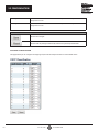
2.1 LOGIN
1.2 USING THE WEB INTERFACE / 1.3 USING THE ONLINE HELP

51. 8 7 7. 8 7 7. 2 2 6 9 BLACKBOX.COM
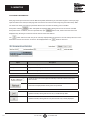
Operation
1.
Type in the User name and Password.
2.
Click ‘Sign in.’
Field Description.
User name Login user name. The maximum length is 32
characters. Default: admin.
Password Login user password. The maximum length is 32
characters. Default: none.
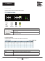
2.2 TREE VIEW
The tree view is a web menu. Use it to view the page for data or configuration.
2.2.1 CONFIGURATION MENU
2.2.2 MONITOR MENU
2. USING THE WEB / 2.1 LOGIN / 2.2 TREE VIEW

61. 8 7 7. 8 7 7. 2 2 6 9 BLACKBOX.COM
2.2.3 DIAGNOSTICS MENU
2.2.4 MAINTENANCE MENU
2.3 CONFIGURATION
2.2 TREE VIEW

71. 8 7 7. 8 7 7. 2 2 6 9 BLACKBOX.COM
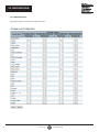
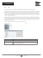
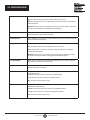
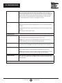
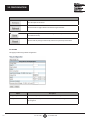
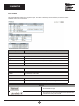
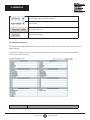
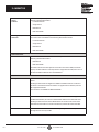
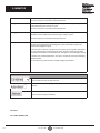
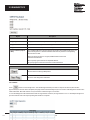
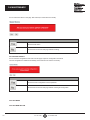
2.3.1 SYS TE M
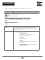
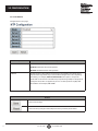
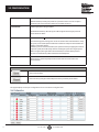
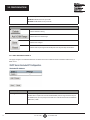
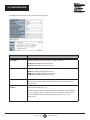
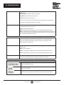
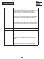
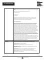
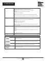
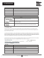
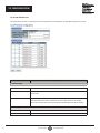
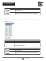
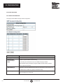
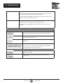
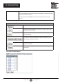
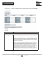
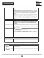
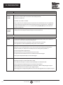
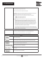
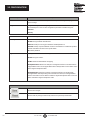
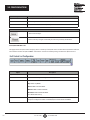
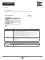
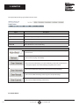
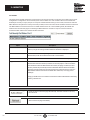
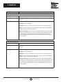
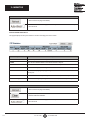
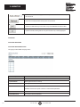
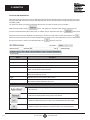
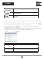
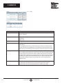
2.3.2 SYSTEM INFORMATION
The switch system information is provided here.
Object
Description
System Contact
The textual identification of the contact person for this managed node (includes
information on how to contact this person). The allowed string length is 0 to 255
characters, and the allowed content is ASCII characters from 32 to 126.
System Name
An administratively assigned name for this managed node. By convention, this is the
node's fully-qualified domain name. A domain name is a text string drawn from the
alphabet (A–Z, a–z), digits (0–9), and minus sign (-). No space characters are per-
mitted as part of a name. The first character must be an alpha character. The first or
last character must not be a minus sign. The allowed string length is
0 to 255 characters.
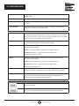
System Location
The physical location of this node (i.e., telephone closet, 3rd floor). The allowed string-
length is 0 to 255 characters, and the allowed content is ASCII characters from
32 to 126.
Buttons
Click to save changes.
Click to revert to previously saved values.
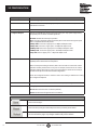
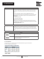
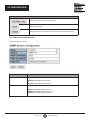
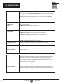
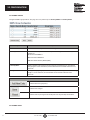
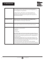
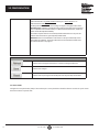
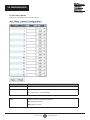
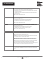
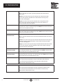
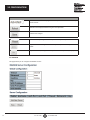
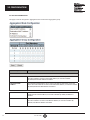
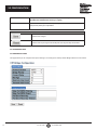
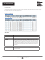
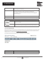
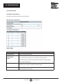
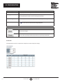
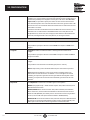
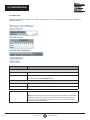
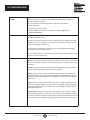
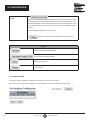
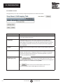
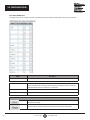
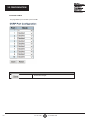
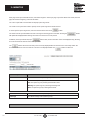
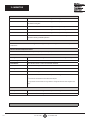
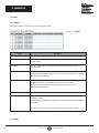
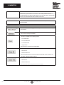
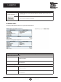
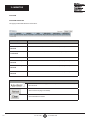
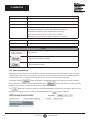
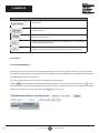
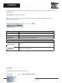
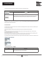
2.3.3 SYSTEM IP
Configure IP basic settings, control IP interfaces, and IP routes.
2.3 CONFIGURATION

81. 8 7 7. 8 7 7. 2 2 6 9 BLACKBOX.COM
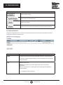
The maximum number of interfaces supported is 8. The maximum number of routes is 32.
Object
Description
IP Configuration
Mode Configure whether the IP stack should act as a ‘Host’ or a ‘Router.’ In ‘Host ‘
mode, IP traffic between interfaces will not be routed. In ‘Router’ mode, traffic is
routed between all interfaces.
DNS Server
This setting controls the DNS name resolution done by the switch.
The following modes are supported:
•
From any DHCP interfaces
The first DNS server offered from a DHCP lease to a
DHCP-enabled interface will be used.
•
No DNS server
No DNS server will be used.
•
Configured
Explicitly provide the IP address of the DNS Server in dotted
decimal notation.
•
From this DHCP interface
Specify from which DHCP-enabled interface a provided DNS
server should be preferred.
2.3 CONFIGURATION

91. 8 7 7. 8 7 7. 2 2 6 9 BLACKBOX.COM
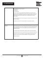
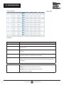
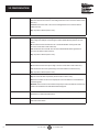
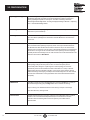
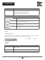
DNS Proxy
When DNS proxy is enabled, the system will relay DNS requests to the currently
configured DNS server, and reply as a DNS resolver to the client devices on the
network.
IP Interfaces
Delete Select this option to delete an existing IP interface.
VLAN
The VLAN associated with the IP interface. Only ports in this VLAN will be able to
access the IP interface. This field is only available for input when creating a new
interface.
IPv4 DHCP Enabled
Enable the DHCP client by checking this box. If this option is enabled, the system
will configure the IPv4 address and mask of the interface using the DHCP protocol.
The DHCP client will announce the configured System Name as hostname to
provide DNS lookup.
IPv4 DHCP Fallback Timeout
The number of seconds for trying to obtain a DHCP lease. After this period expires,
a configured IPv4 address will be used as an IPv4 interface address. A value of
zero disables the fallback mechanism, so that DHCP will keep retrying until a valid
lease is obtained. Legal values are 0 to 4294967295 seconds.
IPv4 DHCP Current Lease
For DHCP interfaces with an active lease, this column shows the current interface
address, as provided by the DHCP server.
IPv4 Address
The IPv4 address of the interface in dotted decimal notation.
If DHCP is enabled, this field configures the fallback address. The field may be left
blank if IPv4 operation on the interface is not desired, or no DHCP fallback address is
desired.
IPv4 Mask
The IPv4 network mask in number of bits (prefix length). Valid values are between 0
and 30 bits for an IPv4 address.
If DHCP is enabled, this field configures the fallback address network mask. The
field may be left blank if IPv4 operation on the interface is not desired, or no DHCP
fallback address is desired.
IPv6 Address
The IPv6 address of the interface. An IPv6 address is a 128-bit record represented as
eight fields of up to four hexadecimal digits with a colon separating each field (:). For
example, fe80::215:c5ff:fe03:4dc7. The symbol :: is a special syntax that can be used
as a shorthand way of representing multiple 16-bit groups of contiguous zeros, but it
can only appear once. It can also represent a legally valid IPv4 address. For example,
::192.1.2.34.
The field may be left blank if IPv6 operation on the interface is not desired.
2.3 CONFIGURATION

10 1. 8 7 7. 8 7 7. 2 2 6 9 BLACKBOX.COM
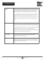
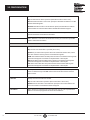
IPv6 Mask
The IPv6 network mask in number of bits (prefix length). Valid values are between 1
and 128 bits for an IPv6 address.
The field may be left blank if IPv6 operation on the interface is not desired.
IP Routes
Delete Select this option to delete an existing IP route.
Network The destination IP network, or host address of this route. Valid format is
dotted decimal notation or a valid IPv6 notation. A default route can use the
value 0.0.0.0 or IPv6 :: notation.
Mask Length
The destination IP network or host mask in number of bits (prefix length). It defines
how much of a network address that must match in order to qualify for this route.
Valid values are between 0 and 32 bits respectively, 128 for IPv6 routes. Only a
default route will have a mask length of 0 (it will match anything).
Gateway The IP address of the IP gateway. Valid format is dotted decimal notation or a valid
IPv6 notation. Gateway and Network must be the same type.
Next Hop VLAN (Only for IPv6)
The VLAN ID (VID) of the specific IPv6 interface associated with the gateway.
The given VID ranges from 1 to 4094 and will be effective only when the
corresponding IPv6 interface is valid.
If the IPv6 gateway address is link-local, it must specify the next hop VLAN
for the gateway.
If the IPv6 gateway address is not link-local, the system ignores the next hop
VLAN for the gateway.
Buttons
Click to add a new IP interface. A maximum of 8 interfaces are supported.
Click to add a new IP route. A maximum of 32 routes are supported.
Click to save changes.
Click to revert to previously saved values.
2.3 CONFIGURATION

11 1. 8 7 7. 8 7 7. 2 2 6 9 BLACKBOX.COM
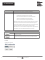
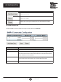
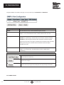
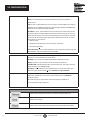
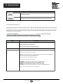
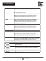
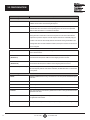
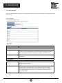
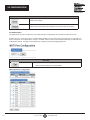
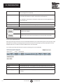
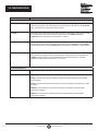
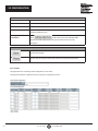
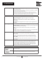
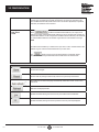
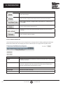
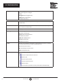
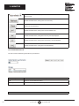
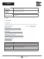
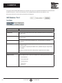
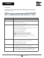
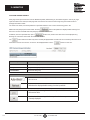
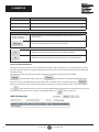
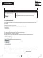
2.3.4 SYSTEM NTP
Configure NTP on this page.
Object
Description
Mode Indicates the NTP mode operation. Possible modes are:
Enabled: Enable NTP client mode operation.
Disabled: Disable NTP client mode operation.
Server #
Provide the IPv4 or IPv6 address of a NTP server. IPv6 address is a 128-bit record
represented as eight fields of up to four hexadecimal digits with a colon separating
each field (:). For example, fe80::215:c5ff:fe03:4dc7. The symbol :: is a special
syntax that can be used as a shorthand way of representing multiple 16-bit groups of
contiguous zeros, but it can appear only once. It can also represent a legally valid
IPv4 address. For example, ::192.1.2.34.
Buttons
Click to save changes.
Click to undo any changes made locally and revert to previously saved values.
2.3 CONFIGURATION

12 1. 8 7 7. 8 7 7. 2 2 6 9 BLACKBOX.COM
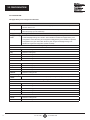
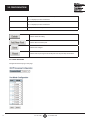
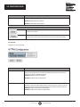
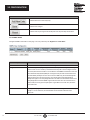
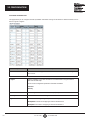
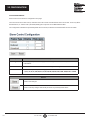
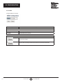
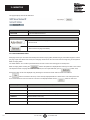
2.3.5 SYSTEM TIME
This page allows you to configure the Time Zone.
Time Zone Configuration
Time Zone Lists various time zones worldwide. Select the appropriate time zone from the drop-down list
and click ‘Save’ to set.
Acronym User can set the acronym of the time zone. This is a user-configurable acronym to identify the
time zone (range: up to 16 characters).
Daylight Saving Time Configuration
Daylight Saving
Time
This is used to set the clock forward or backward according to the configurations set below for
a defined Daylight Saving Time duration. Select 'Disable' to disable the Daylight Saving Time
configuration. Select 'Recurring' and configure the Daylight Saving Time duration to repeat the
configuration every year. Select 'Non-Recurring' and configure the Daylight Saving Time
duration for single time configuration (default: Disabled).
Recurring Configurations
Start Time Settings
Week Select the starting week number.
Day Select the starting day.
Month Select the starting month.
Hours Select the starting hour.
Minutes Select the starting minute.
End Time Settings
Week Select the ending week number.
Day Select the ending day.
Month Select the ending month.
Hours Select the ending hour.
Minutes Select the ending minute.
Offset Settings
Offset Enter the number of minutes to add during Daylight Saving Time (range: 1 to 1440).
Non-Recurring Configurations
Start Time Setting
Month Select the starting month.
Date Select the starting date.
Year Select the starting year.
Hours Select the starting hour.
Minutes Select the starting minute.
End Time Settings
Month Select the ending month.
Date Select the ending date.
2.3 CONFIGURATION

13 1. 8 7 7. 8 7 7. 2 2 6 9 BLACKBOX.COM
Year Select the ending year.
Hours Select the ending hour.
Minutes Select the ending minute.
Offset Settings
Offset Enter the number of minutes to add during Daylight Saving Time (range: 1 to 1440).
Date/Time Configuration
Date/Time Settings
Year Year of current date time (range: 2000 to 2037).
Month Month of current date time.
Date Date of current date time.
Hours Hour of current date time.
Minutes Minute of current date time.
Seconds Second of current date time.
Buttons
Click to save changes.
Click to undo any changes made locally and revert to previously saved values.
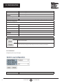
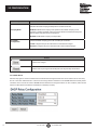
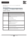
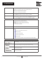
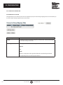
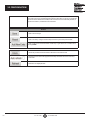
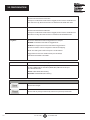
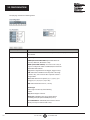
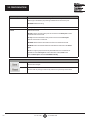
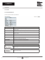
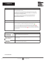
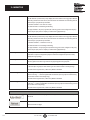
2.3.6 SYSTEM LOG
Configure System Log on this page.
Object Description
2.3 CONFIGURATION

14 1. 8 7 7. 8 7 7. 2 2 6 9 BLACKBOX.COM
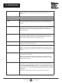
Server Mode Indicates the server mode operation. When the mode operation is enabled, the
syslog message will be sent out to the syslog server. The syslog protocol is based
on UDP communication and received on UDP port 514. The syslog server will not
send acknowledgments back to the sender, since UDP is a connectionless protocol
and does not provide acknowledgments. The syslog packet will always be sent
out, even if the syslog server does not exist. Possible modes are:
Enabled: Enable server mode operation.
Disabled: Disable server mode operation.
Server Address Indicates the IPv4 host address of the syslog server. If the switch provides a DNS
feature, it also can be a host name.
Syslog Level Indicates what kind of message will be sent to the syslog server. Possible modes are:
Info: Send information, warnings, and errors.
Warning: Send warnings and errors.
Error: Send errors.
Buttons
Click to save changes.
Click to undo any changes made locally and revert to previously saved values.
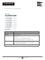
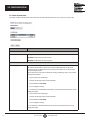
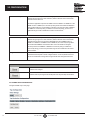
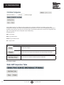
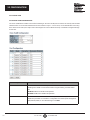
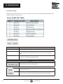
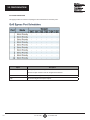
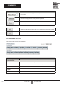
2.3.7 SYSTEM ALARM PROFILE
2.3 CONFIGURATION

15 1. 8 7 7. 8 7 7. 2 2 6 9 BLACKBOX.COM
Alarm Profile is provided here to enable/disable alarms.
Object Description
ID The identification of the Alarm Profile entry.
Description Alarm Type Description.
Enabled If alarm entry is Enabled, then the alarm will be shown in alarm history/current
when it occurs.
Alarm LED will be on (lit); Alarm Relay will also be enabled.
SNMP trap will be sent if any SNMP trap entry exists and is enabled.
Disabled If alarm entry is Disabled, the alarm will not be captured/shown in the
alarm history/current when an alarm occurs; it will not trigger the Alarm
LED change, Alarm Relay, and SNMP trap.
NOTE: When any alarm exists, the Alarm LED will be on (lit); Alarm Output Relay will also be enabled.
2.3 CONFIGURATION

16 1. 8 7 7. 8 7 7. 2 2 6 9 BLACKBOX.COM
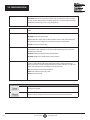
Buttons
Click to save changes.
Click to undo any changes made locally and revert to previously saved values.
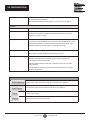
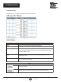
2.3.8 PORT POWER SAVINGS
This page allows the user to configure the Port Power Savings features.
Object Description
Port Power Savings Configuration
Optimize EEE for The switch can be set to optimize EEE for either best power saving or least traffic
latency.
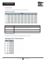
Port Configuration
Port The switch port number of the logical port.
2.3 CONFIGURATION

17 1. 8 7 7. 8 7 7. 2 2 6 9 BLACKBOX.COM
ActiPHY Link down power savings enabled.
ActiPHY works by lowering the power for a port when there is no link. The port is
powered up for short moment to determine if a cable is inserted.
PerfectReach Cable length power savings enabled.
PerfectReach works by determining the cable length and lowering the power for
ports with short cables.
EEE Controls whether EEE is enabled for this switch port.
For maximizing power savings, the circuit isn't started when transmit data is ready
for a port, but is instead queued until a burst of data is ready to be transmitted. This
will give some traffic latency.
If desired, you can minimize the latency for specific frames by mapping the frames to
a specific queue (done with QOS), and then marking the queue as an urgent queue.
When an urgent queue gets data to be transmitted, the circuits will be powered
up at once and the latency will be reduced to the wakeup time.
EEE Urgent Queues Queues set will activate transmission of frames as soon as data is available.
Otherwise, the queue will postpone transmission until a burst of frames can
be transmitted.
Buttons
Click to save changes.
Click to undo any changes made locally and revert to previously saved values.
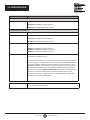
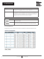
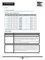
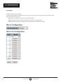
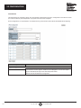
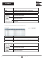
2.3.9 PORT
This page displays current port configurations. Ports can also be configured here.
2.3 CONFIGURATION

18 1. 8 7 7. 8 7 7. 2 2 6 9 BLACKBOX.COM
Object
Description
Port This is the logical port number for this row.
Link
The current link state is displayed graphically. Green indicates the link is up and red
indicates that it is down.
Current Link Speed
Provides the current link speed of the port.
Configured Link Speed
Selects any available link speed for the given switch port. Only speeds supported by
the specific port are shown. Possible speeds are:
Disabled - Disables the switch port operation.
Auto - Port auto-negotiates speed with the link partner and selects the highest speed
that is compatible with the link partner.
10Mbps HDX - Forces the copper port in 10-Mbps half-duplex mode.
10Mbps FDX - Forces the copper port in 10-Mbps full-duplex mode.
100Mbps HDX - Forces the copper port in 100-Mbps half-duplex mode.
100Mbps FDX - Forces the copper port in 100-Mbps full-duplex mode.
1Gbps FDX - Forces copper port in 1-Gbps full-duplex mode.
Flow Control
When Auto Speed is selected on a port, this section indicates the flow control
capability that is advertised to the link partner.
When a fixed-speed setting is selected, that is what is used. The Current Rx column
indicates whether pause frames on the port are obeyed, and the Current Tx column
indicates whether pause frames on the port are transmitted. The Rx and Tx settings
are determined by the result of the last Auto-Negotiation.
Check the configured column to use flow control. This setting is related to the setting
for Configured Link Speed.
Maximum Frame Size
Enter the maximum frame size allowed for the switch port, including FCS.
Excessive Collision Mode
Configure port transmit collision behavior.
Discard: Discard frame after 16 collisions (default).
Restart: Restart back off algorithm after 16 collisions.
Buttons
Click to save changes.
Click to undo any changes made locally and revert to previously saved values.
Click to refresh the page. Any changes made locally will be undone.
2.3 CONFIGURATION

19 1. 8 7 7. 8 7 7. 2 2 6 9 BLACKBOX.COM
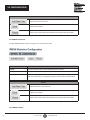
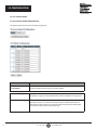
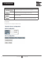
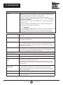
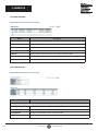
2.3.10 DHCP SERVER MODE
This page configures global mode and VLAN mode to enable/disable DHCP server per system and per VLAN.
Object Description
Global Mode
Mode Configure the operation mode per system. Possible modes are:
Enabled: Enable DHCP server per system.
Disabled: Disable DHCP server pre system.
VLAN Mode
VLAN Range Indicate the VLAN range in which DHCP server is enabled or disabled. The first VLAN
ID must be smaller than or equal to the second VLAN ID. But, if the VLAN range
contains only one VLAN ID, then you can just input it into either one of the first and
second VLAN ID, or both.
On the other hand, if you want to disable an existing VLAN range, then you can follow
the steps listed below:
1.
Press to add a new VLAN range.
2.
Input the VLAN range that you want to disable.
3.
Choose Mode to be Disabled.
4.
Press to apply the change.
5.
You will see that the disabled VLAN range is removed from the DHCP Server mode
configuration page.
6.
Press to add a new VLAN range.
7.
Input the VLAN range that you want to disable.
8.
Choose Mode to be Disabled.
9.
Press to apply the change.
10.
You will see the disabled VLAN range is removed from the DHCP Server mode
configuration page.
2.3 CONFIGURATION

20 1. 8 7 7. 8 7 7. 2 2 6 9 BLACKBOX.COM
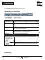
MODE Indicate the operation mode per VLAN. Possible modes are:
Enabled: Enable DHCP server per VLAN.
Disabled: Disable DHCP server pre VLAN.
Buttons
Click to delete the setting.
Click to add a new VLAN range.
Click to save changes.
Click to undo any changes made locally and revert to previously saved values.
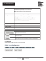
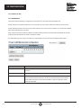
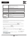
2.3.11 DHCP SERVER EXCLUDED IP
This page configures excluded IP addresses. A DHCP server will not allocate these excluded IP addresses to a
DHCP client.
Object Description
IP Range Define the IP range to be excluded in IP addresses. The first excluded IP must be
smaller than or equal to the second excluded IP. But, if the IP range contains only one
excluded IP, then you can just input it to either one of the first and second excluded IP
addresses, or both.
2.3 CONFIGURATION
Page is loading ...
Page is loading ...
Page is loading ...
Page is loading ...
Page is loading ...
Page is loading ...
Page is loading ...
Page is loading ...
Page is loading ...
Page is loading ...
Page is loading ...
Page is loading ...
Page is loading ...
Page is loading ...
Page is loading ...
Page is loading ...
Page is loading ...
Page is loading ...
Page is loading ...
Page is loading ...
Page is loading ...
Page is loading ...
Page is loading ...
Page is loading ...
Page is loading ...
Page is loading ...
Page is loading ...
Page is loading ...
Page is loading ...
Page is loading ...
Page is loading ...
Page is loading ...
Page is loading ...
Page is loading ...
Page is loading ...
Page is loading ...
Page is loading ...
Page is loading ...
Page is loading ...
Page is loading ...
Page is loading ...
Page is loading ...
Page is loading ...
Page is loading ...
Page is loading ...
Page is loading ...
Page is loading ...
Page is loading ...
Page is loading ...
Page is loading ...
Page is loading ...
Page is loading ...
Page is loading ...
Page is loading ...
Page is loading ...
Page is loading ...
Page is loading ...
Page is loading ...
Page is loading ...
Page is loading ...
Page is loading ...
Page is loading ...
Page is loading ...
Page is loading ...
Page is loading ...
Page is loading ...
Page is loading ...
Page is loading ...
Page is loading ...
Page is loading ...
Page is loading ...
Page is loading ...
Page is loading ...
Page is loading ...
Page is loading ...
Page is loading ...
Page is loading ...
Page is loading ...
Page is loading ...
Page is loading ...
Page is loading ...
Page is loading ...
Page is loading ...
Page is loading ...
Page is loading ...
Page is loading ...
Page is loading ...
Page is loading ...
Page is loading ...
Page is loading ...
Page is loading ...
Page is loading ...
Page is loading ...
Page is loading ...
Page is loading ...
Page is loading ...
Page is loading ...
Page is loading ...
Page is loading ...
Page is loading ...
Page is loading ...
Page is loading ...
Page is loading ...
Page is loading ...
Page is loading ...
Page is loading ...
Page is loading ...
Page is loading ...
Page is loading ...
Page is loading ...
Page is loading ...
Page is loading ...
Page is loading ...
Page is loading ...
Page is loading ...
Page is loading ...
Page is loading ...
Page is loading ...
Page is loading ...
Page is loading ...
Page is loading ...
Page is loading ...
Page is loading ...
Page is loading ...
Page is loading ...
Page is loading ...
Page is loading ...
Page is loading ...
Page is loading ...
Page is loading ...
Page is loading ...
Page is loading ...
Page is loading ...
Page is loading ...
Page is loading ...
Page is loading ...
Page is loading ...
Page is loading ...
Page is loading ...
Page is loading ...
Page is loading ...
Page is loading ...
Page is loading ...
Page is loading ...
Page is loading ...
Page is loading ...
Page is loading ...
Page is loading ...
Page is loading ...
Page is loading ...
Page is loading ...
Page is loading ...
Page is loading ...
Page is loading ...
Page is loading ...
Page is loading ...
Page is loading ...
Page is loading ...
Page is loading ...
Page is loading ...
Page is loading ...
Page is loading ...
Page is loading ...
Page is loading ...
Page is loading ...
Page is loading ...
Page is loading ...
Page is loading ...
Page is loading ...
Page is loading ...
Page is loading ...
Page is loading ...
Page is loading ...
Page is loading ...
Page is loading ...
Page is loading ...
Page is loading ...
Page is loading ...
Page is loading ...
Page is loading ...
Page is loading ...
Page is loading ...
Page is loading ...
Page is loading ...
Page is loading ...
Page is loading ...
Page is loading ...
Page is loading ...
Page is loading ...
Page is loading ...
Page is loading ...
Page is loading ...
Page is loading ...
Page is loading ...
Page is loading ...
Page is loading ...
Page is loading ...
Page is loading ...
Page is loading ...
Page is loading ...
Page is loading ...
Page is loading ...
Page is loading ...
Page is loading ...
Page is loading ...
Page is loading ...
Page is loading ...
Page is loading ...
Page is loading ...
Page is loading ...
Page is loading ...
Page is loading ...
Page is loading ...
Page is loading ...
Page is loading ...
Page is loading ...
Page is loading ...
Page is loading ...
Page is loading ...
Page is loading ...
Page is loading ...
Page is loading ...
Page is loading ...
Page is loading ...
Page is loading ...
-
 1
1
-
 2
2
-
 3
3
-
 4
4
-
 5
5
-
 6
6
-
 7
7
-
 8
8
-
 9
9
-
 10
10
-
 11
11
-
 12
12
-
 13
13
-
 14
14
-
 15
15
-
 16
16
-
 17
17
-
 18
18
-
 19
19
-
 20
20
-
 21
21
-
 22
22
-
 23
23
-
 24
24
-
 25
25
-
 26
26
-
 27
27
-
 28
28
-
 29
29
-
 30
30
-
 31
31
-
 32
32
-
 33
33
-
 34
34
-
 35
35
-
 36
36
-
 37
37
-
 38
38
-
 39
39
-
 40
40
-
 41
41
-
 42
42
-
 43
43
-
 44
44
-
 45
45
-
 46
46
-
 47
47
-
 48
48
-
 49
49
-
 50
50
-
 51
51
-
 52
52
-
 53
53
-
 54
54
-
 55
55
-
 56
56
-
 57
57
-
 58
58
-
 59
59
-
 60
60
-
 61
61
-
 62
62
-
 63
63
-
 64
64
-
 65
65
-
 66
66
-
 67
67
-
 68
68
-
 69
69
-
 70
70
-
 71
71
-
 72
72
-
 73
73
-
 74
74
-
 75
75
-
 76
76
-
 77
77
-
 78
78
-
 79
79
-
 80
80
-
 81
81
-
 82
82
-
 83
83
-
 84
84
-
 85
85
-
 86
86
-
 87
87
-
 88
88
-
 89
89
-
 90
90
-
 91
91
-
 92
92
-
 93
93
-
 94
94
-
 95
95
-
 96
96
-
 97
97
-
 98
98
-
 99
99
-
 100
100
-
 101
101
-
 102
102
-
 103
103
-
 104
104
-
 105
105
-
 106
106
-
 107
107
-
 108
108
-
 109
109
-
 110
110
-
 111
111
-
 112
112
-
 113
113
-
 114
114
-
 115
115
-
 116
116
-
 117
117
-
 118
118
-
 119
119
-
 120
120
-
 121
121
-
 122
122
-
 123
123
-
 124
124
-
 125
125
-
 126
126
-
 127
127
-
 128
128
-
 129
129
-
 130
130
-
 131
131
-
 132
132
-
 133
133
-
 134
134
-
 135
135
-
 136
136
-
 137
137
-
 138
138
-
 139
139
-
 140
140
-
 141
141
-
 142
142
-
 143
143
-
 144
144
-
 145
145
-
 146
146
-
 147
147
-
 148
148
-
 149
149
-
 150
150
-
 151
151
-
 152
152
-
 153
153
-
 154
154
-
 155
155
-
 156
156
-
 157
157
-
 158
158
-
 159
159
-
 160
160
-
 161
161
-
 162
162
-
 163
163
-
 164
164
-
 165
165
-
 166
166
-
 167
167
-
 168
168
-
 169
169
-
 170
170
-
 171
171
-
 172
172
-
 173
173
-
 174
174
-
 175
175
-
 176
176
-
 177
177
-
 178
178
-
 179
179
-
 180
180
-
 181
181
-
 182
182
-
 183
183
-
 184
184
-
 185
185
-
 186
186
-
 187
187
-
 188
188
-
 189
189
-
 190
190
-
 191
191
-
 192
192
-
 193
193
-
 194
194
-
 195
195
-
 196
196
-
 197
197
-
 198
198
-
 199
199
-
 200
200
-
 201
201
-
 202
202
-
 203
203
-
 204
204
-
 205
205
-
 206
206
-
 207
207
-
 208
208
-
 209
209
-
 210
210
-
 211
211
-
 212
212
-
 213
213
-
 214
214
-
 215
215
-
 216
216
-
 217
217
-
 218
218
-
 219
219
-
 220
220
-
 221
221
-
 222
222
-
 223
223
-
 224
224
-
 225
225
-
 226
226
-
 227
227
-
 228
228
-
 229
229
-
 230
230
-
 231
231
-
 232
232
-
 233
233
-
 234
234
-
 235
235
-
 236
236
-
 237
237
-
 238
238
-
 239
239
-
 240
240
-
 241
241
-
 242
242
-
 243
243
-
 244
244
-
 245
245


Black Box LIG1080A Owner's manual
- Category
- Network switches
- Type
- Owner's manual
Ask a question and I''ll find the answer in the document
Finding information in a document is now easier with AI
Related papers
-
Black Box LGB5028A-R2 Owner's manual
-
-
Black Box LGB5124A-R2 Owner's manual
-
Black Box LGB1110A Owner's manual
-
-
-
-
-
-
Other documents
-
 EtherWAN EX26262F Series User manual
-
MicroNet SP6526P User manual
-
ICP DAS USA FSM-510G-4F User manual
-
Edge-Core ECIS4500-8P4F User manual
-
Digisol DG-IS4508HP User manual
-
Repotec RP-PG1518W Owner's manual
-
Repotec RP-PG1510W Owner's manual
-
Transition Networks SISGM1040-184D-LRT User guide
-
-
 SignaMax C-500 48 Port Gigabit PoE+ Full Power Managed Switch User guide

