Page is loading ...

97B0123N02
Issue Date: January 24, 2023
Installation, Operation &
Maintenance
Geothermal Open Loop Water-to-
Water HNW Series
Water-to-Water
Water-Source Heat Pumps

Model Nomenclature 3
Safety 4
General Information 4
Physical Data 6
Dimensional Data 7
Unit Installation 8
Water Connection Installation 8
Ground-Water Heat Pump Applications 9
Water Quality Requirements 11
Load Side Plumbing Installation 14
Hot Water Generator 15
Electrical – Line Voltage 18
Electrical – Low Voltage Wiring 19
Controls – DXM2.5 20
Unit Commissioning & Operating Limits 21
Unit & System Checkout 22
Unit Start-Up Procedure 23
Operating Pressures 25
Preventive Maintenance 27
Troubleshooting Form 28
Warranty 29
Revision History 32
Table of Contents
Installation, Operation, Maintenance
2
Installation, Operation & Maintenance - HNW Water to Water Series

Model Nomenclature
WARNING!
WARNING! HNW IS FOR GROUND WATER
INSTALLATIONS ONLY. Installing HNW on closed loop system
will void warranty and unit will not be eligible for federal tax credit.
Installation, Operation, Maintenance 3
Installation, Operation & Maintenance - HNW Water to Water Series
H N W A036 C1 11 C F B
1 2 3 4 5 6 7
8
9 10 11 12 13 14
HN = Heat Controller High Efficiency
Series
W = Water To Water
Configuration
Unit Size
036
060
120
Revision Level
A = Current Revision
Voltage
Controls
0 = Residential
Cabinet
Hot Water Generator
Source Water Coil
N = Cupro-Nickel
C = Copper
N = Cupro-Nickel
Load Water Coil
0 = None
F = Front
Water Connection Location
D = DXM2.5
1 = 208-230/60/1

General Information
WARNING!
WARNING!
CAUTION!
WARNING! To avoid the release of refrigerant into the
atmosphere, the refrigerant circuit of this unit must be
serviced only by technicians who meet local, state, and
federal prociency requirements.
WARNING! All refrigerant discharged from this unit must
be recovered WITHOUT EXCEPTION. Technicians must
follow industry accepted guidelines and all local, state,
and federal statutes for the recovery and disposal of
refrigerants. If a compressor is removed from this unit,
refrigerant circuit oil will remain in the compressor. To
avoid leakage of compressor oil, refrigerant lines of the
compressor must be sealed after it is removed.
CAUTION! To avoid equipment damage, DO NOT use
these units as a source of heating or cooling during the
construction process. The mechanical components and
lters can quickly become clogged with construction dirt
and debris, which may cause system damage and void
product warranty.
WARNING!
WARNING! This product can expose you to chemicals
including Carbon Black, which is known to the State of
California to cause cancer and Methanol, which is known
to the State of California to cause birth defects or other
reproductive harm. For more information go to
www.P65Warnings.ca.gov
The following warning complies with State of California law,
Proposition 65.
SAFETY
Warnings, cautions and notices appear throughout this
manual. Read these items carefully before attempting any
installation, service, or troubleshooting of the equipment.
DANGER: Indicates an immediate hazardous situation, which
if not avoided will result in death or serious injury. DANGER
labels on unit access panels must be observed.
WARNING: Indicates a potentially hazardous situation, which
if not avoided could result in death or serious injury.
CAUTION: Indicates a potentially hazardous situation or an
unsafe practice, which if not avoided could result in minor or
moderate injury or product or property damage.
NOTICE: Notication of installation, operation or maintenance
information, which is important, but which is not hazard-
related.
Installation, Operation, Maintenance
4
Installation, Operation & Maintenance - HNW Water to Water Series

General Information, Cont'd.
CAUTION!
CAUTION!
CAUTION! DO NOT store or install units in corrosive
environments or in locations subject to temperature or
humidity extremes (e.g., attics, garages, rooftops, etc.).
Corrosive conditions and high temperature or humidity
can signicantly reduce performance, reliability, and
service life. Always move and store units in an upright
position. Tilting units on their sides will cause equipment
damage.
CAUTION! CUT HAZARD - Failure to follow this caution
may result in personal injury. Sheet metal parts may have
sharp edges or burrs. Use care and wear appropriate
protective clothing, safety glasses and gloves when
handling parts and servicing heat pumps.
Installation, Operation, Maintenance 5
Installation, Operation & Maintenance - HNW Water to Water Series
INSPECTION
Upon receipt of the equipment, carefully check the shipment
against the bill of lading. Make sure all units have been
received. Inspect the carton or crating of each unit, and
inspect each unit for damage. Assure the carrier makes
proper notation of any shortages or damage on all copies of
the freight bill and completes a common carrier inspection
report. Concealed damage not discovered during unloading
must be reported to the carrier within 15 days of receipt
of shipment. If not led within 15 days, the freight
company can deny the claim without recourse. Note: It
is the responsibility of the purchaser to le all necessary
claims with the carrier. Notify the Heat Controlller Trafc
Department of all damage within fteen (15) days of
shipment.
STORAGE
Equipment should be stored in its original packaging in a
clean, dry area. Store units in an upright position at all times.
The stack limit for HNW036, 060 and 120 is three.
UNIT PROTECTION
Cover units on the job site with either shipping packaging,
vinyl lm, or an equivalent protective covering. Cap the open
ends of pipes stored on the job site. In areas where painting,
plastering, and/or spraying has not been completed, all due
precautions must be taken to avoid physical damage to the
units and contamination by foreign material. Physical damage
and contamination may prevent proper start-up and may
result in costly equipment clean-up.
Examine all pipes, ttings, and valves before installing any of
the system components. Remove any dirt or trash found in or
on these components.
PRE-INSTALLATION
Installation, Operation, and Maintenance instructions are
provided with each unit.. The installation site chosen should
include adequate service clearance around the unit. Before
unit start-up, read all manuals and become familiar with
the unit and its operation. Thoroughly check the system
before operation.
PREPARE UNITS FOR INSTALLATION AS FOLLOWS:
1. Compare the electrical data on the unit nameplate with
ordering and shipping information to verify that the
correct unit has been shipped.
2. Keep the cabinet covered with the shipping packaging
until installation is complete and all plastering, painting,
etc. is nished.
3. Verify refrigerant tubing is free of kinks or dents and that
it does not touch other unit components.
4. Inspect all electrical connections. Connections must be
clean and tight at the terminals.

Physical Data
Installation, Operation, Maintenance
6
Installation, Operation & Maintenance - HNW Water to Water Series
Model 036 060 120
Compressor (qty) Scroll (1) Scroll (2)
Factory Charge HFC-410A (oz) [kg] Per
Circuit 72 [2.04] 96 [2.49] 96 [2.49]
Water Connection Size
Source/Load 1" Swivel 1-1/2 FPT
HWG (in) 1" Swivel 1/2" FPT
Weight - Operating (lbs) [kg] 348 [158] 360 [163] 726 [329]
Weight - Packaged (lbs) [kg] 373 [169] 385 [175] 770 [349]
Water Volume (Source)
Gallons (Liters) 0.96 (3.64) 1.33 (5.04) 2.65 (10.02)
Dual isolated compressor mounting
Balanced port expansion valve (TXV)
Insulated Source and Load Water Coils standard
Insulated Refrigerant Circuit standard
Compressor on (green) and fault (red) light

B
C
A
M
L
K
1.0
(2.5 cm)
1
2
3
4
56
J
H
G
F
E
D
1
2
3
4
5
6
Required
Service Access
Optional
Service Access
Required
Service Access
Optional
Service Access
B
C
A
1.8
(4.6 cm)
1.3
(3.3 cm)
2.7
(6.9 cm)
(18.3 cm)
(4.3 cm)
1.0
(2.5 cm)
7.2
1.7
3 Ft
3 Ft
Notes 1 & 2
3 Ft
Notes 1 & 2
Notes 1 & 2
3 Ft
Notes 1 & 2
(7.4 cm)
2.9
(10.1 cm)
4.0
TMW
036-060
TMW 120
K
L
M
B
C
A
M
L
K
1.0
(2.5 cm)
1
2
3
4
56
J
H
G
F
E
D
1
2
3
4
5
6
Required
Service Access
Optional
Service Access
Required
Service Access
Optional
Service Access
B
C
A
1.8
(4.6 cm)
1.3
(3.3 cm)
2.7
(6.9 cm)
(18.3 cm)
(4.3 cm)
1.0
(2.5 cm)
7.2
1.7
3 Ft
3 Ft
Notes 1 & 2
3 Ft
Notes 1 & 2
Notes 1 & 2
3 Ft
Notes 1 & 2
(7.4 cm)
2.9
(10.1 cm)
4.0
TMW
036-060
TMW 120
K
L
M
Notes:
1. 3 feet front access is required, both sides access
is optional preferred for service access. However,
all components may be serviced from the front
access panel if side access is not available.
2. While clear access to all removable panels is not
required, installer should take care to comply with
all building codes and allow adequate clearance
for future eld services.
HNW 036, 060
HNW 120
Water to
Water
Overall Cabinet
Water Connections
Electric Access Plugs
1 2 3 4 5 6
A
Depth
B
Width
C
Height
D
Source
(Outdoor)
Water In
E
Source
(Outdoor)
Water Out
F
Load
(Indoor)
Water In
G
Load
(Indoor)
Water Out
H
HWG
Water In
J
HWG
Water
Out
K
Low
Voltage
L
External
Pump
M
Power
Supply
036-060 in. 30.6 25.4 33 2.7 9.4 19.4 24.5 27.9 30.4 20.9 22.9 30.9
cm. 77.8 64.5 83.8 6.9 23.9 49.3 62.2 70.9 77.2 53.1 58.2 78.5
120 in. 30.6 52.9 37 25.2 25.2 30.1 30.1 34.9 34.9 29.9 31.9 34.4
cm. 77.8 134.4 94 64.0 64.0 76.5 76.5 88.6 88.6 75.9 81.0 87.4
Installation, Operation, Maintenance 7
Installation, Operation & Maintenance - HNW Water to Water Series
Dimensional Data

Unit Installation
UNIT LOCATION
These units are not designed for outdoor installation. Locate
the unit in an INDOOR area that allows enough space for
service personnel to perform typical maintenance or repairs.
The installation of water source heat pump units and all
associated components, parts and accessories which
make up the installation shall be in accordance with
the regulations of ALL authorities having jurisdiction
and MUST conform to all applicable codes. It is the
responsibility of the Installing Contractor to determine and
comply with ALL applicable codes and regulations.
Locate the unit in an indoor area that allows easy removal of
access panels, and has enough space for service personnel
to perform maintenance or repair. Provide sufcient room
to make water and electrical connections. Any access panel
screws that would be difcult to remove after the unit is
installed should be removed prior to setting the unit. These
units are not approved for outdoor installation and, therefore,
must be installed inside the structure being conditioned. Do
not locate in areas subject to freezing or where humidity
levels can cause cabinet condensation.
Residential models using swivel piping ttings for water
connections are rated for 450 psi (3101 kPa) operating
pressure. The connections have a rubber gasket seal similar
to a garden hose gasket, which when mated to the ush
end of most 1” threaded male pipe ttings provides a
leak-free seal without the need for thread sealing tape or
joint compound. Insure that the rubber seal is in the swivel
connector prior to attempting any connection (rubber seals
are shipped attached to the swivel connector). DO NOT
OVER TIGHTEN or leaks may occur.
FPT CONNECTIONS (SIZE 120)
Pipe joint compound is not necessary when Teon threaded
tape is pre-applied to hose assemblies or when ared-end
connections are used. If pipe joint compound is preferred,
use compound only in small amounts on the pipe threads of
the tting adapters. Prevent sealant from reaching the ared
surfaces of the joint.
NOTE: When antifreeze is used in the loop, assure that
it is compatible with Teon tape or pipe joint compound
employed.
Maximum allowable torque for brass ttings is 30 ft-lbs [41
N-m]. If a torque wrench is not available, tighten nger-tight
plus one quarter turn. Tighten steel ttings as necessary.
Gasket
Swivel Nut
Stainless steel
snap ring
Brass Adaptor
Hand Tighten
Only!
Do Not
Overtighten!
WATER CONNECTION INSTALLATION
WARNING!
WARNING! Polyolester Oil, commonly known as POE
oil, is a synthetic oil used in many refrigeration systems
including those with HFC-410A refrigerant. POE oil, if it
ever comes in contact with PVC or CPVC piping, may
cause failure of the PVC/CPVC. PVC/CPVC piping should
never be used as supply or return water piping with water
source heat pump products containing HFC-410A as
system failures and property damage may result.
The female locking ring is threaded onto the pipe threads
which holds the male pipe end against the rubber gasket,
and seals the joint. HAND TIGHTEN ONLY! DO NOT
OVERTIGHTEN!
Installation, Operation, Maintenance
8
Installation, Operation & Maintenance - HNW Water to Water Series

Ground-Water Heat Pump Applications
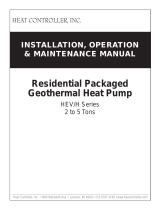
OPEN LOOP: GROUND-WATER SYSTEMS
Typical open loop piping is shown in Figure 2. Shut off valves
should be included for ease of servicing. Boiler drains or
other valves should be “tee’d” into the lines to allow acid
ushing of the heat exchanger. Shut off valves should be
positioned to allow ow through the coaxial heat exchanger
via the boiler drains without allowing ow into the piping
system. P/T plugs should be used so that pressure drop and
temperature can be measured. Supply and return water
piping should be limited to copper, HPDE, or other acceptable
high temperature material. Note that PVC or CPVC material
is not recommended as they are not compatible with the
polyolester oil used in HFC-410A products.
Water quantity should be plentiful and of good quality.
Consult water quality table for guidelines. The unit comes
standard with either a copper or cupro-nickel source water
heat exchanger. Consult Table 1 for recommendations. In
conditions anticipating heavy scale formation or in brackish
water, a cupro-nickel heat exchanger is recommended. In
ground water situations where scaling could be heavy or
where biological growth such as iron bacteria will be present,
an open loop system is not recommended. Heat exchanger
coils may over time lose heat exchange capabilities due to
build up of mineral deposits. Heat exchangers must only
be serviced by a qualied technician, as acid and special
pumping equipment is required. Desuperheater coils can
likewise become scaled and possibly plugged. In areas with
extremely hard water, the owner should be informed that
the heat exchanger may require occasional acid ushing.
In some cases, the desuperheater option should not be
recommended due to hard water conditions and additional
maintenance required.
WATER QUALITY REQUIREMENTS
Scaling potential should be assessed using the pH/
Calcium hardness method. If the pH < 7.5 and the Calcium
hardness is less than 100 ppm, scaling potential is low. If
this method yields numbers out of range of those listed, the
Ryznar Stability and Langelier Saturation indexes should be
calculated. Use the appropriate scaling surface temperature
for the application, 150°F [66°C] for direct use (well water/
open loop) and HWG (desuperheater); 85°F [29°C] for
indirect use. A monitoring plan should be implemented in
these probable scaling situations. Other water quality issues
such as iron fouling, corrosion prevention and erosion and
clogging should also be considered.
EXPANSION TANK AND PUMP
Use a closed, bladder-type expansion tank to minimize
mineral formation due to air exposure. The expansion tank
should be sized to provide at least one minute continuous
run time of the pump using its drawdown capacity rating to
prevent pump short cycling. Discharge water from the unit
is not contaminated in any manner and can be disposed
of in various ways, depending on local building codes (e.g.
recharge well, storm sewer, drain eld, adjacent stream
or pond, etc.). Most local codes forbid the use of sanitary
sewer for disposal. Consult your local building and zoning
department to assure compliance in your area.
The pump should be sized to handle the home’s domestic
water load (typically 5-9 gpm [23-41 l/m]) plus the ow
rate required for the heat pump. Pump sizing and expansion
tank must be chosen as complimentary items. For example,
an expansion tank that is too small can causing premature
pump failure due to short cycling. Variable speed pumping
applications should be considered for the inherent energy
savings and smaller expansion tank requirements.
WATER CONTROL VALVE
Always maintain water pressure in the heat exchanger
by placing the water control valve(s) on the discharge line
to prevent mineral precipitation during the off-cycle. Pilot
operated slow closing valves are recommended to reduce
water hammer. If water hammer persists, a mini-expansion
tank can be mounted on the piping to help absorb the excess
hammer shock. Insure that the total ‘VA’ draw of the valve
can be supplied by the unit transformer. For instance, a slow
closing valve can draw up to 35VA. This can overload smaller
40 or 50 VA transformers depending on the other controls
in the circuit. A typical pilot operated solenoid valve draws
approximately 15VA. Note the special wiring diagrams later
in this manual for slow closing valves.
FLOW REGULATION
Flow regulation can be accomplished by two methods. One
method of ow regulation involves simply adjusting the ball
valve or water control valve on the discharge line. Measure
the pressure drop through the unit heat exchanger, and
determine ow rate from tables located later in this manual.
Since the pressure is constantly varying, two pressure
gauges may be needed. Adjust the valve until the desired
ow of 1.5 to 2 gpm per ton [2.0 to 2.6 l/m per kW] is
achieved. A second method of ow control requires a ow
control device mounted on the outlet of the water control
valve. The device is typically a brass tting with an orice of
rubber or plastic material that is designed to allow a specied
ow rate. On occasion, ow control devices may produce
velocity noise that can be reduced by applying some back
pressure from the ball valve located on the discharge line.
Slightly closing the valve will spread the pressure drop over
both devices, lessening the velocity noise. NOTE: When
EWT is below 50°F [10°C], a minimum of 2 gpm per ton
(2.6 l/m per kW) is required.
LOAD WATER COIL LOW TEMPERATURE LIMIT SETTING
For all open loop systems, if the leaving water is below 40°F
(4.4°C), must use antifreeze and clip JW2 (factory setting-
water) to avoid freeze damage to the unit. See “Low Water
Temperature Cutout Selection” in this manual for details on
the low limit setting.
Installation, Operation, Maintenance 9
Installation, Operation & Maintenance - HNW Water to Water Series

Figure 2: Typical Open Loop/ Well Application
Air Pad or
Extruded
polystyrene
insulation board
Unit Power
Disconnect
Pressure
Tank
Flow
Regulator
Water
Control
Valve
P/T Plugs
Water Out
Shut-Off
Valve
Boiler
Drains
Water In
Optional
Filter
Aquastat and Change Over Wiring
CAUTION!
CAUTION! Many units are installed with a factory or eld
supplied manual or electric shut-o valve. DAMAGE WILL
OCCUR if shut-o valve is closed during unit operation. A
high pressure switch must be installed on the heat pump
side of any eld provided shut-o valves and connected to
the heat pump controls in series with the built-in refrigerant
circuit high pressure switch to disable compressor
operation if water pressure exceeds pressure switch
setting. The eld installed high pressure switch shall
have a cut-out pressure of 300 psig and a cut-in pressure
of 250 psig. This pressure switch can be ordered from
Heat Controller with a 1/4” internal are connection as part
number 39B0005N02.
Ground-Water Heat Pump Applications, Cont'd.
CAUTION!
CAUTION! Refrigerant pressure activated water regulating
valves should never be used with Heat Controlller
equipment.
Installation, Operation, Maintenance
10
Installation, Operation & Maintenance - HNW Water to Water Series

Water Quality Requirements
Installation, Operation, Maintenance 11
Installation, Operation & Maintenance - HNW Water to Water Series
pH - Chilled Water 0.7F°58< to 9.0 7.0 to 9.0 7.0 to 9.0 7.0 to 9.0
pH - Heated Water 0.8F°58> to 10.0 8.0 to 10.0 8.0 to 10.0 8.0 to 10.0
Alkalinity
(
HCO3
)
ppm - CaCO
3
equiv. 50 to 500 50 to 500 50 to 500 50 to 500
Calcium (Ca)ppm <100 <100 <100 <100
Magnesium (Mg)ppm <100 <100 <100 <100
Total Hardness (CaCO3)ppm - CaCO3 equiv. 30 to 150 150 to 450 150 to 450 150 to 450
Langelier Satura�on Index LSI -0.5 to +0.5 -0.5 to +0.5 -0.5 to +0.5 -0.5 to +0.5
Ryznar Stability 5.6ISRxednI to 8.0 6.5 to 8.0 6.5 to 8.0 6.5 to 8.0
Total Dissolved Solids (TDS) ppm - CaCO
3
equiv. <1000 <1000 <1000 <1500
Sulfate (SO
4
2-
)ppm <200 <200 <200 <200
Nitrate(NO
3
-
)001<001<001<001<mpp
Chlorine (free)(Cl) ppm <0.5 <0.5 <0.5 <0.5
Chloride (water < 80°F) ppm <20 <20 <150 <150
Chloride (water > 120°F) ppm <20 <20 <125 <125
Hydrogen Sulfide
α
(H
2
S) 5.0<5.0<5.0<5.0<bpp
Carbon Dioxide (CO
2
)ppm 0 <50 10 to 50 10 to 50
Iron Oxide (Fe) ppm <1.0 <1.0 <1.0 <0.2
Manganese (Mn)ppm < 0.4 <0.4 <0.4 <0.4
Ammonia (NH
3
)ppm <0.05 <0.1 <0.1 <0.1
Chloramine (NH
2
CL) ppm 0 0 0 0
Iron 0000Lm/sllecairetcaB
Slime Forming 0000Lm/sllecairetcaB
Sulfate reducing 0000Lm/sllecairetcab
Suspended Solids
β
01<01<01<01<mpp)SST(
Earth Ground Resistance
χ
0smhO
Consult NEC & local electrical codes for grounding requirements
Electrolysis Voltage
δ
003<Vm
Measure voltage internal water loop to HP ground
Leakage Current
δ
51<Am
Measure current in water loop pipe
Building Primary Electrical Ground to unit, must meet local diameter and penetra�on length requirements
WATER QUALITY REQUIREMENTS
For Closed-Loop and Open-Loop Systems
All Heat Exchanger
Types
COAXIAL HX Copper
Tube in Tube
COAXIAL HX
Cupronickel
Brazed Plate HX
316 SS
Symbol UnitsDescrip�on
Electrolysis
All HX types Scaling Poten�alCorrosion Preven�on
(Cl
-
)
Fouling &
Biological
Do not connect heat pump to steel pipe unless dissimilar materials are separated by using Di-electric unions. Galvanic corrosion of heat
pump water pipe will occur.
Heat Exchanger Type
Closed Loop
Recircula�ng Open Loop, Tower, Ground Source Well
-
Table 1: Water Quality Requirements
Clean water is essential to the performance and life span of water source heat pumps. Contaminants, chemicals, and minerals
all have the potential to cause damage to the water heat exchanger if not treated properly. All closed water loop systems
should undergo water quality testing and be maintained to the water quality requirements listed in this table.

Water Quality Requirements, Cont'd.
1. The Heat Controlller Water Quality Table provides water
quality requirements for coaxial & brazed plate heat
exchangers.
2. The water must be evaluated by an independent testing
facility comparing site samples against this Table. When
water properties are outside of these parameters, the
water must either be treated by a professional water
treatment specialist to bring the water quality within
the boundaries of this specication, or an external
secondary heat exchanger must be used to isolate the
heat pump water system from the unsuitable water.
Failure to do so will void the warranty of the heat pump
system and will limit liability for damage caused by leaks
or system failure.
3. Regular sampling, testing and treatment of the water
is necessary to assure that the water quality remains
within acceptable levels thereby allowing the heat pump
to operate at optimum levels.
4. If closed‐loop systems are turned off for extended
periods, water samples must be tested prior to operating
the system.
5. For optimal performance, it is recommended that the
closed‐loop piping systems are initially lled with de‐
ionized water.
6. Well water with chemistry outside of these boundaries,
and salt water or brackish water requires an external
secondary heat exchanger. Surface/Pond water should
not be used.
7. If water temperature is expected to fall below 40°F,
antifreeze is required. Refer to the heat pump IOM for
the correct solution ratios to prevent freezing.
Strainer / Filter Sizing
Mesh Size Particle Size
Microns MM Inch
20 840 0.840 0.0340
30 533 0.533 0.0210
60 250 0.250 0.0100
100 149 0.149 0.0060
150 100 0.100 0.0040
200 74 0.074 0.0029
ppm = parts per million
ppb = parts per billion
α Hydrogen Sulde has an odor of rotten eggs. If one
detects this smell, a test for H2S must be performed. If
H2S is detected above the limit indicated, remediation is
necessary (Consult with your Water Testing/Treatment
Professional) or a secondary heat exchanger is required
using appropriate materials as recommended by the
heat exchanger supplier.
β Suspended solids and particulates must be ltered to
prevent fouling and failure of heat exchangers. Strainers
or particulate lters must be installed to provide a
maximum particle size of 600 micron (0.60 mm, 0.023
in.) using a 20 to 30 mesh screen size. When a loop is
installed in areas with ne material such as sand or clay,
further ltration is required to a maximum of 100 micron.
Refer to the Strainer / Filter Sizing Chart to capture the
particle sizes encountered on the site.
χ An electrical grounding system using a dedicated
ground rod meeting NEC and Local Electrical codes must
be installed. Building Ground must not be connected the
WSHP piping system or other plumbing pipes.
δ Refer to IOM for instructions on measuring resistance
and leakage currents within water loops.
Do not use PVC pipe for water loop (compressor POE
oil and glycols damage PVC) use of HDPE pipe is
recommended.
Installation, Operation, Maintenance
12
Installation, Operation & Maintenance - HNW Water to Water Series

Water Quality Requirements, Cont'd.
OHM meter
Measuring Earth Ground Resistance
0.02�
Building
Ground Rod
Well Casing
Measure the earth ground bond using an Ohm meter between the building's ground rod and the steel well casing.
The resistance measured should be zero Ohms. The NEC allows a resistance to ground up to 20 Ohms. Any
resistance above zero, indicates a poor earth ground which may be the result of a hot neutral line or that
conduc�ve water is present. Both of these may lead to electrolysis and corrosion of the heat pump piping. A check
for both should be performed and resolved.
Note if the well casing is plas�c, a conduc�ve path can be achieved by inser�ng a #6 AWG bare copper wire into the
well water. Remove the temporary conductor when finished.
Measuring Electrolysis Voltage and Current
Volt Meter
300mV
Heat Pump
Wire Electrode inserted into port for
Voltage measurement
Pete's Port
HP Piping
Amp Sensor to VOM for Current
Water-in
Water-out
Measure the electrolysis voltage using a volt meter between the heat pump ground and a #14 AWG solid copper
wire electrode inserted into the water using a Pete’s style access port.
The HP must be opera�ng and the water stream flowing.
The voltage measured should be less than 300mV (0.300 V). If higher than 500mV electrolysis will occure and
corrosion will result.
If voltage is measured, the cause is a high resistance earth ground or current on the neutral conductor. Remedial
measures should be performed.
Measure the current flowing through the piping system by using an amp clamp probe on the water-in line. The HP
must be opera�ng and the water stream flowing.
There should be zero amps measured. If current is present, there is leakage current to the plumbing system and it
must be rec�fied to prevent pipe corrosion.
Installation, Operation, Maintenance 13
Installation, Operation & Maintenance - HNW Water to Water Series

Load Side Plumbing Installation
Installation, Operation, Maintenance
14
Installation, Operation & Maintenance - HNW Water to Water Series
HNW UNIT LOAD PLUMBING
The applications are too varied to describe in this document.
However, some basic guidelines will be presented. All plumbing
should conform to local codes with the following considerations:
Wide temperature variation applications such as heating/
cooling coils:
• Employ piping materials that are rated for the
maximum temperature and pressure combination.
This excludes PVC for most heating applications.
• Insure that load water ow in high temperature
heating applications is at least 3 gpm per ton [3.9 l/m
per kW] to improve performance and reduce nuisance
high pressure faults.
• DO NOT employ plastic to metal threaded joints
• Utilize a pressure tank and air separator vent system
to equalize pressure and remove air.
Swimming Pool Hot Tub Applications:
• Load side should be isolated with secondary heat
exchanger constructed of anti-corrosion material in all
chlorine/bromine uid applications.
Potable Water Applications:
• Load side should always be isolated with secondary
heat exchanger for use in potable water systems.
• Insure load water ow in high temperature heating
applications is at least 3 gpm per ton to improve
performance and reduce nuisance to high
pressure faults.
NOTE: The manufacturer strongly recommends all piping
connections, both internal and external to the unit, be
pressure tested by an appropriate method prior to any
nishing of the interior space or before access to all
connections is limited. Test pressure may not exceed
the maximum allowable pressure for the unit and all
components within the water system. The manufacturer
will not be responsible or liable for damages from water
leaks due to inadequate or lack of a pressurized leak test,
or damages caused by exceeding the maximum pressure
rating during installation.

Hot Water Generator
Hot Outlet
to House
Powered
Water
Heater
Upper
element to
120 - 130°F
[49 - 54°C]
Lower
element to
100 - 110°F
[38 - 43°C]
Cold Inlet from
Domestic supply
Shut-off
Valve #4
Shut-off
Valve #1
Insulated water lines -
5/8” OD, 50 ft maximum (one way) meters
[16mm OD, 15 meters maximum]
Shut Off
Valve #2
Shut-off
Valve #3
In
Out
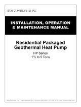
Figure 3: Typical HWG Installation
Insulated water lines - 5/8” OD, 50 ft maximum (one way)
[16mm OD, 15 meters maximum]
Upper element to 130°F [54°C]
(or owner preference)
Cold Inlet
Hot Outlet to
house
Powered
Water Heater
Cold Inlet from
Domestic supply
Hot Outlet
Unpowered
Water Heater
Field Supplied 3/4” brass nipple and “T”
Lower element to 120°F [49°C]
Shut-off
Valve #1
Shut-off
Valve #4
Shut-off
Valve #3
Shut Off
Valve #2
In
Out
Figure 4: HWG Double Tank Installation
WARNING!
WARNING!
A 150°F setpoint may lead to scalding or
burns. The 150°F setpoint must only be used on systems
that employ an approved anti-scald valve.
The HWG (Hot Water Generator) or desuperheater option
provides considerable operating cost savings by utilizing
heat energy from the compressor discharge line to help
satisfy domestic hot water requirements. The HWG is active
throughout the year, providing virtually free hot water when
the heat pump operates in the cooling mode or hot water at
the COP of the heat pump during operation in the heating
mode. Actual HWG water heating capacities are provided in
the appropriate heat pump performance data.
Heat pumps equipped with the HWG option include a built-
in water to refrigerant heat exchanger that eliminates the
need to tie into the heat pump refrigerant circuit in the eld.
The control circuit and pump are also built in for residential
equipment. Figure 3 shows a typical example of HWG water
piping connections on a unit with built-in circulating pump.
This piping layout prevents sludge/debris from the bottom of
the tank being pulled into the HWG pump.
The temperature setpoint of the HWG is eld selectable
to 125°F or 150°F. The 150°F setpoint allows more heat
storage from the HWG. For example, consider the amount of
heat that can be stored by the HWG when using the 125°F
setpoint, versus the amount of heat that can be generated by
the HWG when using the 150°F setpoint.
In a typical 50 gallon two-element electric water heater
the lower element should be turned down to 100°F, or the
lowest setting, to get the most from the HWG. The tank will
eventually stratify so that the lower 80% of the tank, or 40
gallons, becomes 100°F (controlled by the lower element).
The upper 20% of the tank, or 10 gallons, will be maintained
at 125°F (controlled by the upper element).
Using a 125°F setpoint, the HWG can heat the lower 40
gallons of water from 100°F to 125°F, providing up to 8,330
btu’s of heat. Using the 150°F setpoint, the HWG can heat
the same 40 gallons of water from 100°F to 150°F and
the remaining 10 gallons of water from 125°F to 150°F,
providing a total of up to 18,743 btu’s of heat, or more than
twice as much heat as when using the 125°F setpoint.
Electric water heaters are recommended. If a gas, propane,
or oil water heater is used, a second preheat tank must be
installed (Figure 4). If the electric water heater has only a
single center element, the dual tank system is recommended
to insure a usable entering water temperature for the HWG.
Typically a single tank of at least 50 gallons (189 liters) is
used to limit installation costs and space. However, a dual
tank, as shown in Figure 4, is the preferred system, as it
provides the maximum storage and temperate source water
to the HWG.
It is always advisable to use water softening equipment on
domestic water systems to reduce the scaling potential and
lengthen equipment life. In extreme water conditions, it may
be necessary to avoid the use of the HWG option since the
potential cost of frequent maintenance may offset or exceed
any savings. Consult Table 1 for scaling potential tests.
Installation, Operation, Maintenance 15
Installation, Operation & Maintenance - HNW Water to Water Series

Hot Water Generator, Cont'd.
INSTALLATION
The HWG is controlled by two sensors and the DXM2.5
microprocessor control. One sensor is located on the
compressor discharge line to sense the discharge
refrigerant temperature. The other sensor is located on the
HWG heat exchanger’s “Water In” line to sense the potable
water temperature.
WARNING!
WARNING!
Under no circumstances should the sensors
be disconnected or removed. Full load conditions can drive
hot water tank temperatures far above safe temperature
levels if sensors are disconnected or removed.
The DXM2.5 microprocessor control monitors the refrigerant
and water temperatures to determine when to operate
the HWG. The HWG will operate any time the refrigerant
temperature is sufciently above the water temperature.
Once the HWG has satised the water heating demand
during a heat pump run cycle, the controller will cycle the
pump at regular Intervals to determine if an additional HWG
cycle can be utilized.
When the control is powered and the HWG pump output is
active for water temperature sampling or HWG operation,
the DXM2.5 status LED will slowly ash (On 1 second, Off
1 second).
If the control has detected a HWG fault, the DXM2.5 status
LED will ash a numeric fault code as follows:
High Water Temperature (> 160ºF) 5 ashes
Hot Water Sensor Fault 6 ashes
Compressor Discharge Sensor Fault 6 ashes
Fault code ashes have a duration of 0.3 seconds with
a 10 second pause between fault codes. For example, a
“Compressor Discharge Sensor Fault” will be six ashes 0.3
seconds long, then a 10 second pause, then six ashes again,
etc.
WARNING!
WARNING!
Using 150°F setpoint on the HWG will result
in water temperatures sucient to cause severe physical
injury in the form of scalding or burns, even when the hot
water tank temperature setting is visibly set below 150°F.
The 150°F HWG setpoint must only be used on systems
that employ an approved anti-scald valve (part number
(AVAS4) at the hot water storage tank with such valve
properly set to control water temperatures distributed to
all hot water outlets at a temperature level that prevents
scalding or burns.
Figure 5: Anti-Scald Valve Piping Connections
C
H
M
WATER HEATER
CHECK VALVE
8” M AX
HOT WATER
TO HOUSE
ANTI-SCALD
VALVE
ANTI-SCALD
VALVE PIPING
CONNECTIONS
COLD WATER
SUPPLY
Hot Water Generator settings are determined by DIP
switches 3-2, 3-3, and 3-4.
DIP 3-2 controls the HWG Test Mode. It provides for forced
operation of the HWG output, activating the HWG pump for
up to ve minutes.
ON = HWG test mode, OFF = normal HWG operation.
The control will revert to standard operation after ve
minutes regardless of switch position.
DIP 3-3 determines HWG setpoint temperature. It provides
for selection of the HWG operating setpoint.
ON = 150°F (66°C), OFF = 125°F (52°C).
DIP 3-4 is for the HWG status. It provides HWG operation
control.
ON = HWG mode enabled, OFF = HWG mode disabled.
Units are shipped from the factory with this switch in the
OFF position.
Figure 6: Hot Water Generator Settings
P1
Alarm
Relay
Comp
Relay
O
Y1
Y2
W
G
C
R
AL1
24Vdc
EH1
EH2
P6
R
C
Off On
JW3
A
OVR
ESD
C
R
NSB
AL2
JW1
Acc1
Relay
Acc2
Relay
H
COM1
NC1
NO1
COM2
NC2
NO2
P3
CO
RV
RV
LT1
LT1
LT2
LT2
LP
LP
HP
HP
P7
Status
Fault
R
R
CC
CCG
CO
S1
S2
1
12
1
4
e
sU yrotcaF
(240Vac)
Com
N.O.
Fan Enable
7"
Micro
U1
Off On
P2
COH
COM
AO2
P11
Gnd T1
P10
T2 T2 T3 T3 T4 T4 T5
P9
T5
T6 T6
A0-1 A0-2
Off On
S3
RV
Relay
CCH
Relay
Test
P5
B-
Gnd
P4
A+ 24V
(240Vac)
Fan Speed
N.O.
N.C.
12V
OUT
Gnd
P8
IN
NC
P12
1 2 3 4
1 2 3 4 5 6 7 8
1 2 3 4 5 6 7 8
Hot Water
Generator
Settings
Installation, Operation, Maintenance
16
Installation, Operation & Maintenance - HNW Water to Water Series

Hot Water Generator, Cont'd.
WARNING!
WARNING!
The HWG pump is fully wired from the
factory. Use extreme caution when working around
the microprocessor control as it contains line voltage
connections that presents a shock hazard that can cause
severe injury or death.
The heat pump, water piping, pump, and hot water tank
should be located where the ambient temperature does
not fall below 50°F [10°C]. Keep water piping lengths at a
minimum. DO NOT use a one way length greater than 50 ft.
(one way) [15 m]. See Table 2 for recommended piping sizes
and maximum lengths.
All installations must be in accordance with local codes. The
installer is responsible for knowing the local requirements,
and for performing the installation accordingly. DO NOT
activate the HWG (turn DIP 3-4 to the ON position) until
“Initial Start-Up” section, below is completed. Powering the
pump before all installation steps are completed will damage
the pump.
WATER TANK PREPARATION
1. Turn off power or fuel supply to the hot water tank.
2. Connect a hose to the drain valve on the water tank.
3. Shut off the cold water supply to the water tank.
4. Open the drain valve and open the pressure relief valve
or a hot water faucet to drain tank.
5. When using an existing tank, it should be ushed with
cold water after it is drained until the water leaving the
drain hose is clear and free of sediment.
6. Close all valves and remove the drain hose.
7. Install HWG water piping.
HWG WATER PIPING
1. Using at least 1/2” [12.7 mm] I.D. copper, route and install
the water piping and valves as shown in Figures 21 or
22. Install an approved anti-scald valve if the 150°F HWG
setpoint is or will be selected. An appropriate method
must be employed to purge air from the HWG piping.
This may be accomplished by ushing water through the
HWG (as in Figures 21 and 22) or by installing an air vent
at the high point of the HWG piping system.
2. Insulate all HWG water piping with no less than 3/8
inches [10 mm] wall closed cell insulation.
3. Open both shut off valves and make sure the tank drain
valve is closed.
WATER TANK REFILL
1. Close valve #4. Ensure that the HWG valves (valves #2
and #3) are open. Open the cold water supply (valve #1)
to ll the tank through the HWG piping. This will force
water ow through the HWG and purge air from the
HWG piping.
2. Open a hot water faucet to vent air from the system until
water ows from faucet; turn off faucet. Open valve #4.
3. Depress the hot water tank pressure relief valve handle
to ensure that there is no air remaining in the tank.
4. Inspect all work for leaks.
5. Before restoring power or fuel supply to the water
heater, adjust the temperature setting on the tank
thermostat(s) to insure maximum utilization of the heat
available from the refrigeration system and conserve
the most energy. On tanks with both upper and lower
elements and thermostats, the lower element should
be turned down to 100°F [38°C] or the lowest setting;
the upper element should be adjusted to 120-130°F
[49-54°C]. Depending upon the specic needs of the
customer, you may want to adjust the upper element
differently. On tanks with a single thermostat, a preheat
tank should be used (Figure 4).
6. Replace access cover(s) and restore power or fuel supply.
INITIAL START-UP
1. Make sure all valves in the HWG water circuit
are fully open.
2. Turn on the heat pump and allow it to run for
10-15 minutes.
3. Set S3-4 to the “ON” position (enabled) to engage
the HWG. See Figure 6.
4. The HWG pump should not run if the compressor is
not running.
5. The temperature difference between the water entering
and leaving the HWG coil should be approximately
5-10°F [3-6°C].
6. Allow the unit to operate for 20 to 30 minutes to insure
that it is functioning properly.
Table 2: HWG Water Piping Sizes and Length
Unit
Nominal
Tonnage
Nominal HWG
Flow (gpm)
1/2" Copper
(max length*)
3/4" Copper
(max length*)
2.0 0.8 50 -
2.5 1.0 50 -
3.0 1.2 50 -
3.5 1.4 50 -
4.0 1.6 45 50
5.0 2.0 25 50
6.0 2.4 10 50
*Maximum length is equivalent length (in feet) one way of type L copper.
CAUTION!
CAUTION! Use only copper piping for HWG piping due to
the potential of high water temperatures for water that has
been in the HWG heat exchanger during periods of no-ow
conditions (HWG pump not energized). Piping other than
copper may rupture due to high water temperature and
potable water pressure. CPVC, PEX, or other plastic pipe
should not be used HWG piping
Installation, Operation, Maintenance 17
Installation, Operation & Maintenance - HNW Water to Water Series

Electrical – Line Voltage
GENERAL LINE VOLTAGE WIRING
Be sure the available power is the same voltage and phase
as that shown on the unit serial plate. Line and low voltage
wiring must be done in accordance with local codes or the
National Electric Code, whichever is applicable.
POWER CONNECTION
Line voltage connection is made by connecting the incoming
line voltage wires to the power distribution block, or
compressor contactor, refer to unit wiring diagram. Consult
the electrical data table (Table 3) for correct fuse size.
TRANSFORMER
The units are factory wired for 230 Volt. If supply voltage is
208V, transformer must be rewired by installer as illustrated
on the wiring diagram by switching the Red (208V) and the
Orange (230V) at the contactor terminal L1.
LOAD AND SOURCE PUMPS
Wire pumps to unit per unit wire diagram.
Model Voltage
Code Voltage Min/Max
Voltage
Compressor HWG
Pump
FLA
EXT Loop
Pump
FLA
Total
Unit
FLA
Min
Circuit
Amps
Max
Fuse/
HACR
RLA LRA QTY
036 3 208/230/60/1 197/252 16.7 79.0 1 0.5 4.0 21.2 25.3 40
060 3 208/230/60/1 197/252 26.3 134.0 1 0.5 4.0 30.8 37.3 60
120 3 208/230/60/1 197/252 26.3 134.0 2 0.5 4.0 57.1 63.6 80
HACR circuit breaker in USA only
Residential units come standard with 75VA transformer, and optional HWG pump.
WARNING!
WARNING! Disconnect electrical power source to prevent
injury or death from electrical shock.
CAUTION!
CAUTION! Use only copper conductors for eld installed
electrical wiring. Unit terminals are not designed to accept
other types of conductors.
WARNING!
WARNING! To avoid possible injury or death due to
electrical shock, open the power supply disconnect switch
and secure it in an open position during installation.
All eld installed wiring, including electrical ground, must
comply with the National Electrical Code as well as all
applicable local codes.
Refer to the unit wiring diagrams and electrical data
table (Table 3) for fuse sizes and a schematic of the eld
connections which must be made by the installing (or
electrical) contractor.
Consult the unit wiring diagram located on the inside of the
compressor access panel to ensure proper electrical hookup.
All nal electrical connections must be made with a length of
exible conduit to minimize vibration and sound transmission
to the building.
Table 3: HNW Electrical Data
Installation, Operation, Maintenance
18
Installation, Operation & Maintenance - HNW Water to Water Series

Electrical – Low Voltage Wiring
Unit is typically controlled by eld installed and wired
aquastat and mode changeover switch (R to O is cooling
mode). Wire to DXM2.5 P1 terminals, use minimum 18GA
Class II wire.
NOTE: Do not close up unit until checkout is completed.
WATER SOLENOID VALVES
An external solenoid valve(s) (with end switch so valve is fully
open before compressor starts) should be used. Valve should
also be normally closed type so water ows through only
when unit is operating. A slow closing valve may be required
to help reduce water hammer. Typical wiring for a 24VAC
external solenoid valve. Figures 5 or 6 illustrate typical slow
closing water control valve wiring for Taco zone sentry series
(Heat Controlller P/N AMV…) and Taco SBV series valves. Slow
closing valves take approximately 60 seconds to open (very
little water will ow before 45 seconds). Once fully open, an
end switch closure allows the compressor to be energized.
When wired as shown, the slow closing valve will operate
properly with the following notations:
1. The valve will remain open during a unit lockout.
2. The valve will draw approximately 25-35 VA through
the “Y” signal of the aquastat
A-Stat DXM2.5
CC
Y1 Y1
End Switch
TACO VALVE
LED
C
W/Y
Figure 7: Accessory Motorized Water Valve -
Typical Wiring Example #1
Figure 8: Accessory Motorized Water Valve -
Typical Wiring Example #2
C
C
Termostato
Y
1
2
3
Y
AVM
Taco Válvula
Calentador Interruptor
Unidad Empacada
C
C
Aquastat
Y1
1
2
3
Y1
Accessory Motorized
Water Valve
Heater Switch
Unit
Controller
Installation, Operation, Maintenance 19
Installation, Operation & Maintenance - HNW Water to Water Series

DXM2.5 CONTROLS
For detailed controller information,
see the DXM2.5 Application,
Operation, and Maintenance (AOM)
manual (part # 97B0142N01).
Controls – DXM2.5
Installation, Operation, Maintenance
20
Installation, Operation & Maintenance - HNW Water to Water Series
/