Page is loading ...

Owner's
Manual
Model No.
139.53335SRT3
139.53645SRT3
139.53646SRT2
139.53648SRT2
139.53650SRT
139.53660SRT1
139.53834SRT3
For Residential Use
Only
Caution:
Read and follow all
safety rules and
operating instructions
before first use of this
product.
Fasten the manual
near the garage door
after installation.
Complies with UL 325
regulations effective
January 1, 1993
CRAFTSMAN®
GARAGE DOOR OPENER
• Safety Precautions
• Assembly
• Installation
• Adjustment
• Care and Maintenance
• Operation
• Troubleshooting
• Parts List
Sears, Roebuck and Co., Hoffman Estates, IL 60179 U.S.A.

Contents Page
A reviewofsafetyalertsymbols.................................2
You', need tools..........................................................3
Safetyinformationregardinggaragedoorlocks
and ropes..................................................................3
Testingyourgarage doorfar sticking,binding
and b_Jance...............................................................3
Illustretionofsectionaldoor installation.....................4
Illustretionofone-piece doorinstallation...................5
Cartoninventory..........................................................6
Hardwareinventory.....................................................7
Assembly section - pages 8 - 11
AssembleT-reii.........................................................8
Attachcable pulleybracket.......................................8
Installtrolley..............................................................9
Fasten T-reittoopener.............................................9
Installchain/cable ...................................................10
Attachsprocketcover.............................................10
"tightenthe chainandcable ...................................11
Installation section - pages 11-27
Installationsafety instructions.................................11
Determineheaderbracketlocation
Sectionaldoor.......................................................12
One-piecedoor.....................................................13
Installthe headerbracket.......................................14
AttachtheT-rail toheader bracket.........................15
Positiontheopener.................................................16
Hangtheopener.....................................................17
Installthe doorcontrol............................................18
Contents Page
Installthe lightand lens.................................................19
Attachemergencyrelease ropeand handle.................19
Electricalrequirememts.................................................20
Safety reversingsensorinformation..............................21
Installthesafetyreversingsensor...........................22, 23
Fastendoorbracket(sectionaldoor)............................24
Fastendoor bracket(one-piecedoor)...........................25
Connectdoorarm totrolley(sectionaldoor).................26
Connectdoorarmtotrolley(one-piecedoor)...............27
Adjustment section - pages 28 - 30
Travel limitadjustments.................................................28
Forceadjustments.........................................................29
Testthe safetyreversingsensor ...................................30
Testthe safety reversesystem ....................................30
Operationsafetyinstructions...........................................31
Care ofyouropener.........................................................31
Maintenanceschedule....................................................31
Operationofyouropener ................................................32
Receiverand remotecontrolprogramming....................33
Havinga problem?....................................................34, 35
Repairparts, railassembly..............................................36
Repairparts, installation..................................................36
Repairparts,opener assembly.......................................37
Accessories......................................................................38
Index................................................................................39
How toorderrepairparts.................................................40
Maintenanceagreement..................................................40
Warranty..........................................................................40
Start by reviewing these important safety alert symbols
When you see these Safety Symbols on the following pages, they will alert you to the poeslblllty of
serious injury or denthff you do not comply with the corresponding instructions. The hazard may
come from something mechanical or from electric shock. Rend the instructions carefully.
I
A WARNING
I
AWARNING
Mechanical Electrical
I
When you see this Safety Symbol on the following pages, It will alert you to the possibility of damage
to your garage door and/or the garage door opener if you do not comply with the corresponding
instructions. Read the instructions carefully.
I
A CAUTION
This garage door opener is designed and tested to offer safe service provided it is installed, operated,
maintained and tested in strict accordance with the safety Instructions contained in this manual.
2

You'll Need Tools
Duringassembly,installationand adjustment of the opener, instructionswillcallfor hand toolsshownbelow.
Stepladder
Level
Pencil
Tape Measure
oDoolooo O L_
Hack Saw
Wire Cutters
Dnl_ 3/16", 5/16" and
5/32" Dn_l Bits Pliers
Claw Hammer
Adjustable End Wrench
WARNING
An unbalanced garage door might not reverse
when required and someone under the door
could be seriously injured or killed.
If your garage door binds, sticks or is out of
balance, call for professional garage door
service. Garage doora, door springs, cables,
pulleys, brackets and their hardware are under
extreme tension and can cause serious injury
or death. Do not fry to loosen, move or adjust
them yourselfl
Ropes left on a garage door could cause
someone to become entangled and killed.
Remove all ropes connected to the door before
installing and operating the opener,
Identify the type and height of your door and any
special conditions that existand any additional
materials that may be required by referring to the
lists on page 4 or page 5.
CAUTION
To avoid damage to the garage door and
opener, disable locks before installing and
operating the opener. Use a wood screw or nail
to hold locks in the "open" (unlocked) position.
Operation at other than 120V 60 Hz will cause
opener malfunction and damage.
Before you begin, complete the following test to
make sure your door Is balanced, and Is not
sticking or binding:
• Uft the door abouthalfwayas shown. Release the
door. It should stay in place, supported entirely by
its springs.
• Raise and lower the door to see if there is any
binding or sticking.
ONE-PIECE DOOR
3

I SECTIONAL Door Installation I
Before you begin, survey your garage area to
see whether any of the conditions below apply
to your Installation.
Horizontal and vertical reinforcement
is needed forlightWeight garage doors
(fiberglass, steel, aluminum, door withgrass panels, etc.).
See page 24 fordetails.
Slac_ in Chain Tensmn
is Normal Whe_
Garage Door is Closed
FINISHED CEIUNG
Supao_ bracket &
isrequired.
See page 17.
Header Wall
Extension Spring
Floor must be ravel
across width of dOOr
Safety Reversing Sensor
Basedon your particularrequirements, there are
severalinstallationsteps whichmightcall Ior
materials and/or hardwarenot includedin thecarton.
• Step 1, page 12 - Lookat the wall or ceilingabove
the garage door.The header bracket mustbe
securelyfastened to structuralsupports.
• Step 5, page 17 - Do you have a finished ceilingin
yourgarage? If so, a supportbracket and
additional fastening hardware may be required.
• Safety reversingsensor,page 21 - Depending
upon garage construction,wood blocksmay need
to be fastened to mountinglocationsbefore
sensorsare installed.
• Step 10, page 22 - Alternate floor mounting of the
safety reversing sensor will require hardware not
provided.
• Step 11, page 24 - Do you have a steel, aluminum,
fiberglass or glass panel door? It so, horizontal
and vedicel reinforcement is required.
• Look at the garage door where it meets the lloor.
It must close on the floor all the way across.
Other-wise, the safety reverse system may not
work properly. See page 30. Floor or door should
be repaired.
Closed Position
Cable Pulley].,_ I L
BH_ea(_d: Bc:b_ e 3"rolley Rail Assembly
........
o _ Emergency
-- Release
Rope & Handle
s
Curved
Door _:_"_
Heade_ Arm
Wall Door Bracket
Garage
• The opener can be installed within 2 feet of the left
or right of the door center if there is a torsion spring
or center bearing plate in the way of the header
bracket or door bracket area. ff your door has
extension spdngs, the opener must be installed
in the center of the door. See pages 12 and 24.
• Do you have an access door in addition to the
garage door? If not, Model 53702 Emergency
Key Release is required. See page 38.
• It your door is more than 7 feet high, see the longer
rails available on page 38.
You may find it helpful to refer back to this page as you proceed with the installation of your opener.

I ONE-PIECE Door Installation I One-Piece__Door Without Track
Before you begin, survey your garage area to /_
FINISHED CEILING
see whether any of the conditions below apply ____._o _
Supp_= ur_e_
tO your Installation. &lasting _
hardware is required,
Slac_ksinChanom_ntenwtN_nSmn Seepage 17
garage door isdosed,
/z
le
_ Gap _
_ of door rnustnot exceed 1/4".
Safety Reversing Sensor
Based onyourparticularrequirements, thereare
several installationstepswhichmightcell for
materialsand/or hardwarenot includedinthecarton.
• Step 1, page 13 - Lookat the wall or ceilingabove
the garage door.The header bracket mustbe
securelyfastened to structuralsupports.
• Step 5, page 17 - Do you have a finished ceilingin
yourgarage? If so, a supportbracket and
additionalfastening hardware (not provided)may
be required.
• Safety reversingsensor,page 21 - Dependingon
garage construction,wood blocksmay need to be
securelyfastened tomountinglocationsbefore
sensorsare installed.
• Step 10, page 22 - Alternatefloor mountingofthe
safety reversingsensorwillrequirehardware that
is notprovided.
• Step 11, page 25 - Generally, a one-piece door
does not requirereinforcement.If yourdoor is
lightweight, you can refer tothe information
relatingto sectionaldoorson page 24.
• Step 11,page 25 - Dependingon yourdoor's
construction,you might need additionalmounting
hardware for thedoor bracket.
• Do you have an access door in additiontothe
garage door?If not, Model 53702 Emergency
Key Release isrequired.See page 38.
• The gap between the bottom of the garage
door and the floor cannot exceed 1/4".
Otherwise, the safety reverse system may not
work properly. See page 30. The flooror thedoor
shouldbe repaired.
One-Piece Door With Track
Safety acro4ss width of door
Reversing Sensor
Closed Position
Cable Cable Trolley Chain
, Bracket
T-rail
Door
Straight Release
Bracket Door _ Rope & Handle
Arm
You may find It helpful to refer back to this page as
you proceed wIth the installation of your opener.

Carton Inventory
Yourgarage door opener ispackaged in two cartonswhichcontain parts illustratedbelow. Accessorieswill
depend on model purchased. Ifanythingismissing, carefully check the packing material. Parts may be "stuck"
inthe foam. Hardware for assembly and installationis shownon page 7.
MOdels53335 (1),53645 {2),53646(2),
S364S(2), 5365O(2), S3660(_),53S34(2),
Three*Function Remote Control
withVisor Clip
Models 53335, Models 53645, 53646 Models 53650, 53834 Model 53645
53648, 53660
DOOrControl Button Standard Premium
Control Console Control ConSOle Multi-Function
Cable
Pulley Bracket 2*Conduetor Ught Lens
w"it "w " edT o,, °
Center Section
Sprocket Cover
Safety Reversing Sensor _'_7 inDispensing Carton _
Mounting Bracket _ Hanging Brackets
With Square Holes 12)
Curved Door
Arm Saction
Safety Labels (1 Sanding Eye and 1 Receiving Eye) Straight Ooo,
Salety Reversing Sensor and with Arm Section
Mounting Bracket Lderature 2-Conductor White & White/Black BellWire
Wilh Slot (2) attached

Separate all hardware from the packages in the rail carton and the opener carton, as
shown below, for the assembly and installation procedures.
Assembly Hardware
Washered Screw Hex Screw Nut
5/16"-18xl/2' (2) 5/16'-18x7/8" (3) 5/16'-18 (5)
(mounted in Opener)
_!I!'I!/!(!!I!!!/!l!!l'/'/l(!!//!!/II/i/IiIl//ii/I/<O
Trolley Threaded Shaft (1)
Carriage Bolts
1/4"-20xl/2" (4) Master Link(2)
© ©
Lock Washer Lock Nut
5/16' (4) 1/4'-20x7/16 ° (4)
Installation Hardware
l'l'l'l'Jo'J:!0 @
5/16"-9xl -5/8" (2)
Ring
Fastener (3) Nut 5/16"-18 (6)
_lllllllll[llllllllllll_
Lag Screw
5/16"-18x1°7/8' 12)
Hex Screw
5/16"-18x7/8" (4)
(_111111111111111111[1111111[1[111111n_,',',',',',',',',','_
5/, 6Ca._SaS_.2ge,_lt(2) 6ABSCxl"re_2)
Handle
insulated Lock Washer 5/16" (6)
Staples (10)
Dry Wall Anchors (2)
I
Rope
o_ _ o_
Clevis Pin Clevis Pin
5/16"x2-3/4" (1) 5/16"x1" (1)
Clevis Pin
5/16"xi°1/4" (1)
1/4 x1-1/2 ° (4)
_,IIIIIIIIIIIII=I=IIIIIIIII=[=I=IIH=D
Hex Screw
1/4=20x1-1/2"(2)
Safety Reversing Sensor
Installation Hardware
Carriage Bolts
114"-20xl/2 ° (4)
Screw
#10-32x5/8' (4)
©
Lock Nut
1/4'-20 (4)
@
LOCkNut
#10x32 (4)
Wing Nut (2)
Insulated
Staples (20)
7

Assembly Section: Pages 8 - 11
To avoid installation difficulties, do not run the garage door opener until instructed to do so.
Assembly Step 1
Assemble the T-rail & Attach
the Cable Pulley Bracket
• Alignthe 3 T-rail sections on a flat surface exactly
as shown. The end sections are identical. Make
sure the "arrow label" on the center section is
pointing toward the door.
Insert the carriage bolts so the square bolt necks
seat in the square holes in the T-rail end sections
and pass through the round holes in T-rail center
section. Assemble lock nuts, ensure alignment and
tighten.
Make sure bolt necks are
seatedIn thesquare ,_
holesandrailsare
U
alignedbeforeyou
tightenlocknuts.(See
rightandwrongviews).
Improperassemblycan
cause jerky trolley
operation,noiseand/or Right
nuisance door reversals.
Wrong
T-RAiL BACK
(TO OPENER)
T-rail
(End Section)
1/4" Lock Nut
Q
Brace
IfT-reil Isnot assembled I
EXACTLYas shown,trolley ]
willnot travel smoothly I
alonglengl_'tof railor it will
hit againstthe nuts.
T-rail
(Center Seclion)
f Carnage Bolt
T-rail
(End Section)
\
Cable pulley bracket
attaches to FRONT
END of T-fair
Square Carnage
Bolt Holes
T-RAIL FRONT
(TO DOOR)
Positionthecable pulleybracket on thefrontendof the
T-railas shown.Fasten securelywiththe hardware.
Hardware Shown Actual Size
©
Lock Nut Carnage Bolts
1/4" - 20 x 7116" 1/4"- 20 x 1/2"
Hex Screw Nut LockWasher
5/16" - 18 x 7/8" 5/16" - 18 5/16"
Hex Screws
5/16'- 18x7/8"
5/16'
O
Right
Wrong
When tightening
the screws, be
sure to keep
bracket parallel
to the rail.
Otherwise, the
rail may bow
when opener is
operated.
8

Assembly Step 2
Install the Trolley on the T-rail
• Attach the threaded shaft to the trolley with the
lock washer and nuts as shown.
Lock Washer
Outer Nut 5/16"_
Troile_
Temporary Stop
Screwdriver
I
Hardware Shown
Actual Size
LoCk Washer Nut
5/16 ° 5/16" - 18
• As a temporarystop,inserta screwdriverintothe
holein thefront end of the T-rail.
• Slidethe trolleyassembly along the railtothe
screwdriverstop.
If trolley hits against any nuts on the T-ralt, the
bolts and nuts were attached from the wrong
side and must be reposltioned. Review Step 1.
Assembly Step 3
Fasten the T-raft to the Opener I
• Placethe opener on packing materialto protect
the cover. For convenience, puta supportunder
the cable pulleybracket.
i Rernovethe (2) 5/16"-18xl/2" washered screws
mounted in the top ofthe opener.
Alignthe holes in the backsectionofthe T-rail with
the holes inthe opener.
• Fasten the railwith the (2) washered screws
previously removed. Tighten securely.
Remember to use only these screws! Any other
screws will cause serious damage to the opener.
• Inserta 5/16"-18x7/8" hex screw intothe cover
protectionbelt hole in theT-rail as shown.Tighten
securelywith a 5/16" lockwasher and nut,
NOTE: This screw prevents trolley over-travel.
Keep a 2" minimum between the trolley and this
screw when adjusting travel limits (see page 28).
CAUTION
To fasten rail, use only those screws mounted
In the top of the opener. Any other screws will
cause serious damage to the opener.
Washered Screw
5/16"-18xl/2"
Hex Screw
5/16"-18X7/8'
Cover
Protection
5/16"*18
Hardware Shown Actual Size
Hex Screw Nut Lock Washer
_16' - 18 x 718" 5/16"- 18 5/16'

Assembly Step 4
Install the Chain/Cable &
Attach the Sprocket Cover
Dispensing Carton
WARNING
Serious Injury can result If fingers become
entangled In moving opener sprocket. Attach
sprocket cover securely. Never operate opener
while your hand Is near the opener sprocket.
Leave Chain and Cable
Insole DLspensing
Figure 2 Opener
SprOcket
Keep Chain and Cable
Taut When Dispensing
• Detach the cable loop fromthe carton and fastenit
to the trolleywitha master linkfrom the hardware
bag. See master linkprocedure,Figure1.
• Withthe trolleyagainstthe screwdriver,dispense
thecable around the pulley.
Master Link
• Proceed backaroundthe opener sprocket, c_pOnspring
Figure2. Be sure sprocketteeth engage the Master
chain. Continueforward to the trolley UnkCap
threaded shaft, Figure3. MasterLink _"
• Use the second masterlinktoconnect Clip-OnSpnng FlatEnd
of Trolley
Threaded Shaft
thechain tothe flatend of theshaft. Master unreaoeo_na_
Check to make sure the chain Is
not twisted.
• Remove thescrewdriver.
Cable
Loop
Trolley
Master
Link Bar
:abJe Figure 1
Pulley
Figure 3
Chain
T-rail
Pin NOtch
install Chain and Cable
In "PnisDirection
Sprocket
Cover
Back Tab Slat
,o Top at Opener
Front Tab Slot Mounting
Master Link Procedure:
Push pins of master link bar
through cable loop and hole in
front end of trolley. Push cap
over pins and past notches.
Slide clip-on spdng over cap
and into notches until both
pins are securely _ocked.
To attach the sprocket cover:
• Insert the back tab in the opener slot. Squeeze the
cover slightly and insert the front tab in the slot on
the mounting plate.
10

Assembly Step 5
Tighten the Chain & Cable
• Spin the inner nut and lock washer down the
threaded shaft, away from the trolley.
• To tighten the chain, turn outer nut in the direction
shown. As you turn the nut, keep the chain
from twisting.
• When the chain is approximately 1/2" above the
base of the T-rail at its midpoint, re-tighten the
inner nut to secure the adjustment.
Sprocket noise can result if chain is either too
loose or too tight.
When installation iscomplete, you may notice some
chain droop with the door closed. This is normal. If
the chain returns to the position shown when the
door is open, do not re-adjust the chain.
NOTE: During future maintenance, ALWAYS
pull the emergency release handle to disconnect
trolley before adjusting chain.
I
Lock
Outer Nut Washer Inner Nut
___z:_:z:z_T°Tighten Outer Nut _
e__ _ To Tighten
I_n_r NUt
Troll
Chain
II II II I! It II fl II II II
1/2 Inch
I
Base of T-rail
You have now finished assembling your garage door opener. Please read the following
warnings before proceeding to the installation section:
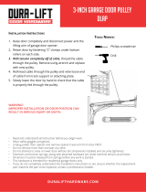
IMPORTANT INSTALLATION INSTRUCTIONS
To reduce the risk of severe injury or death to persons:
1. READ AND FOLLOW ALL INSTALLATION INSTRUCTIONS.
2. Install only on a properly balanced and lubricated garage door. An improperly balanced door
may not reverse and could result in severe injury or death. Repairs to cables, spring assemblies
and other hardware must be made by a professional service person before installing opener.
3. Disable all locks and remove all ropes connected to the garage door before installing the opener.
Ropes connected to a garage door can cause entanglement and death.
4. It possible, install door opener 7 feet or more above floor with the emergency release handle
mounted 6 feet above the floor.
5. Do not connect the opener to power source until instructed to do so.
6. Locate the Door Control within sight of the door at a minimum height of 5 feet where small
children cannot reach and away from all moving parts of the door.
7. Install the User Safety Instruction Label on the wall adjacent to the door control and the
Maintenance Instruction Label in a prominent location on the inside of the garage door.
8. Upon completion of the installation, the door must reverse when it comes in contact with a
one-inch high object or a 2x4 laid flat on the floor.
9. Do not wear watches, rings or loose clothing while installing or servicing an opener. Jewelry or
loose clothing can be caught in the mechanism of the garage door or the opener.
11

Installation Section: Pages 12 - 27
Installation Step 1
Determine Header Bracket Location
Installation procedures vary according to
garage door types. Follow the instructions
which apply to your door.
If the header bracket is not rigidly fastened to
a structural support on the header wall or
ceiling, the safety reverse system may not
work properly (see page 30). The door might
not reverse when required, and could cause
serious injury or death.
The garage door springs, cables, pulleys,
brackets and their hardware are under extreme
tension. Do not attempt to loosen, move or
adjust them yourself. Serious personal injury
or death could result. Call for professional
Vertical -- Ceilin -- garage door service.
Header __ _ Guldehne
Wall
2x4 Structural
Supports _ • Close the door and mark the inside
II1-- vertical centerline of the garage door.
III.IIYP_--_.-_-----__ II I IL,_ 1 • Extend the line onto the header wall
III].dl abovethedoor,
I]u_j IIt II;I __f I Remember, you can fasten the
II I_ L_ I1_1 III IIY/T I header bracket within 2 feet of the
!! IF1--__L--J_i ! left or right of the door center onlyif
II III I/I !l;_e_,_=gI_--I_ ! ] atorsionspringorcenterbearing
I III Ill tl:lG_'_e'i°°lllIit I plate is in the way; or you can attach
li_ ,i _L II L.[] I it to the ceiling (refer to page 14)
II_ Iff III _'1 [ I when clearance is minimal. (It may
11II I III Ill III I ! bemountedonthewallupsidedown
I III Ill _ I I if necessary, to gain approximately
I l 1 L 1/2".)
II tFf_ III Ill Ill I Ifyouneedtoinsta//theheaderbracket
II_Lt t I!1 II_ on a 2x4 (on wall or ceiling), use lag
!l _^I _ ...___ _ screws (not provided) to securely fasten
_ the 2x4 to structural supports as shown
.......... here and on page 13.
• Open your door to the highest
point of travel as shown. Draw
an intersecting horizontal line
on the header wall 2" above
the high point. This height will
provide travel clearance for the
top edge of the door.
Door clearance brackets are
available for sectional doors
when headroom clearance is
less than 2". See accessory
page 38.
Door
Ceiling
Header
_Wall Track
Highest Point
of Travel
Header
Track
of Travel
Proceed to Step 2, page 14.
Sectional door
with curved track
One-piece door
with horizontal track
12

Read the Safety instructions on page 12. They also apply to doors without tracks.
• Close the door and mark the
inside vertical centerline of
your garage door. Extend the
line onto the header wall
above door.
If headroom clearance is
minimal, you can install the
header bracket on the ceiling.
See page 14.
If you need to instal/the
header bracket on a 2x4 (on
wail or ceiling), use lag screws
(not provided) to securely
fasten the 2x4 to structural
supports as shown.
Header Wall
Vertical
Centedine
2x4
OPTIONAL CEILING MOUNT
FOR HEADER BRACKET
Door 1
Jamb
Hardware
Header Wall
Highest Point
of Travel
/
Header Highest Point
_/ Wall of Travel
Ii
One-piece door without track
jamb hardware
One-piece door without track
pivot hardware
• Open your door to the highest point of travel as
shown. Measure the distance from the top of the
door to the floor. Subtract the actual height of the
door. Add 8" to the remainder. (See Example).
Close the door and draw an intersecting horizontal
line on the header wall at the determined height.
If the total number of inches exceeds the height
available in your garage, use the maximum
height possible, or refer to page 14 for ceiling
installation.
EXAMPLE
Distance from top of door
(at highest point of travel) to floor ........................... 92"
Actual height of door ............................................. -88"
Remainder ................................................................ 4"
Add ......................................................................... +8"
Bracket height on header wall ............................... 12"
(Measure UP from top of CLOSED door.)
Proceed to Step 2, page 14.
13

"Installation Step 2 I
Install the Header Bracket
You can attach the header bracket either to the
wall above the garage door, or to the ceiling.
Follow the instructions which will work best for
your particular requirements,
Fasten the Header Bracket to the Wall
• Center the bracket on the vertical guideline with
the bottom edge of the bracket on the horizontal
line as shown (with the arrow pointing toward the
ceiling).
• Mark either set of bracket holes (do not use the
holes designated for ceiling mount). Drill 3/16" pilot
holes and fasten the bracket securely to a structural
support with the hardware provided.
__ Header __
Wall
Lag Screws
5/16"x9xt-5/8"
Wall
Mounting Holes
2x4
Structural
Suppod
J
Highest
Point of Travel
(of Garage Door)
Door
Spdng
Garage
Door
Vertical
Center
Line
The nail hole is for positioning
only. You must use lag screws to
mount the header bracket.
Optional
Wall Mounting
Holes
Hardware Shown Actual Size
q o01rewI>
5/16"-9xl-5/8"
Fasten the Header Bracket to the Ceiling
• Extend the vertical guideline onto the ceiling as
shown.
• Center the bracket on the vertical mark, no more
than 6" from the wall. Make sure the arrow is
pointing toward the wall. The bracket can be
mounted flush against the ceiling when clearance
is minimal.
• Mark holes designated for ceiling mount only. Drill
3/16" pilot holes and fasten bracket securely to a
structural support with the hardware provided.
Ceiling Mounting Holes
Door
Spdng
The nail hole is for positioning only,
You must use lag screws to mount
the header bracket•
Header
Wall
14

Installation Step 3
Attach the T-rail to the Header Bracket
Heade_
Brackel
Cable
Bracket
• Position the opener on the garage floor below the
header bracket. Use packing material as a
protective base.
If the door spring is in the way you'll need help.
Have someone hold the opener securely on a
temporary support to allow the T-rail to clear the
spring.
• Position the cable pulley bracket against the header
bracket.
• Align the bracket holes and join with a clevis pin as
shown.
• Insert a ring fastener to secure.
Ring Fastener
Header Bracket
Clevis Pin
5/16"x2-3/4 ' Cable
Pulley
Bracket
Door
\
Temporary
-- Support
Hardware Shown Actual Size
o]
Clevis Pin
5/16" x 2 3/4'
©
Ring Fastener
15

Installation Step 4
Position the Opener
Follow instructions which apply to your door
type as illustrated.
CAUTION
To prevent damage to steel, aluminum,
fiberglass or glass panel doors, do not rest the
opener on the door without using a 2x4.
SECTIONAL Door & ONE-PIECE Door with Track I
A 2x4 laid flat is convenient for setting an ideal
door-to-T-rail distance.
• Raise the opener onto a stepladder.
You will need help at this point if the ladder is
not tall enough,
• Open the door all the way and place a 2x4 laid flat
on the top section beneath the T-rail.
if the top panel hits the trolley when you raise
the door, pull down on the trolley release arm to
disconnect the inner and outer sections. The
trolley can remain disconnected until Step 12 is
completed,
T-rail 2x4
Door
Stepladder
Trol_se Arm
• With the door fully open and parallel to the floor,
measure the distance from the floor to the top of
the door.
• Using a stepladder as a support, raise the opener
to the same distance as the door from the floor (it
will be at a slight angle as shown).
• The top of the door should be level with the top of
the opener. Do not position the opener more than
2" above this point.
Header
Bracket
I
Top of Opener
Stepladder
16

Installation Step 5
Hang the Opener
Two representative installations are shown.
Yours may be different. Hanging brackets should
be angled, Figure 1, to provide rigidsupport. On
finished ceilings, Figure 2, attach a sturdy metal
bracket to structural supports before installing the
opener. The bracket and fastening hardware are not
_rovided. See accessory page 38.
• Measure the distance from each side of the opener
to the structural support.
• Cut both pieces of the hanging bracket to required
lengths.
• Drill 3/16" pilot holes in the structural supports.
• Attach one end of each bracket to a support with
5/16"-18xl -7/8" lag screws.
• Fasten the opener to the hanging brackets with
5/16"-18x7/8" screws, lock washers and nuts.
• Check to make sure the T-rail is centered over the
door (or in line with the header bracket if the
bracket is not centered above the door).
• Remove the 2x4. Operate the door manually. If the
door hits the rail, raise the header bracket.
Grease the top and underside of the_
rail surface where the trolley __
slides. A tube of grease is /__
supplied.
Hardware Shown Actual Size
I!!l!l!;LI!
5/16'18xl-7/8"
Hex Screw
5/16'- 18x7/8" Nut 5/16"-18 Lock Washer 5/16"
Figure 1
Supports
Measure
Screws
5/15/-18xl-7/8'
5/16'-18x7/8" Screw
_16" Lock Washer
5/16"-18 Nut
Figure 2
Hidden / " _ t
Support I " " /
/. / "_ _ _._f _ _ -- FINISHED CEILING --
- _ Lag Screws
- 5/16 -18xl-7/5/_ _ "
Bracket o o o o _ _- .
. ."-_ ___5/16" Lock Washer.u,
5/16 18_
17

i,
Installation Step 6
Install the Door Control
Locate the door control within sight of the door
at a minimum height of 5 feet where small
children cannot reach, and away from all moving
parts of the door and door hardware.
The door control is typically attached directly to the
wall. If installing into drywall, drill 5/32" holes and
use the anchors provided. For pre-wirad installations
'as in new home construction.), Console models
may be mounted to a standard single gang box
"Figure 2).
1. Strip 1/4" of insulation from one end of the bell
wire and connect it to the two screw terminals on
the back of the door control: white to 2 and
white/red to 1.
2. Door Control Button: Fasten securely with
6ABx1-1/2" screws.
Console Model: Pry off cover along one side
with a screwdriver blade (Figure 1). Fasten with
6ABx1-1/4" self-tapping screws (standard
installation) or 6-32x1" machine screws (pre-wired
installation) as follows:
• Install bottom screw, allowing 1/8" to protrude
above wall surface.
• Position bottom of door control on screw head
and slide down to secure. Adjust screw for snug
fit.
• Install top screw with care to avoid cracking
plastic housing. Do not overtighten.
• Insert top tabs and snap on cover.
3. (For standard installation only) Run the bell wire
up the wall and across the ceiling to the opener.
Use insulated staples to secure the wire in
several places. Be careful not to pierce the wire
with a staple, creating a short.
4. Connect the bell wire to the terminal screws on
the opener panel: white to 2; white/red to 1.
5. Position the antenna wire as shown.
Lighted Lighted
P°shBotto :,
DOOR
CONTROL STANDARD
BuTroN CONTROL
CONSOLE
PREMIUM
CONTROL
CONSOLE
Lighl
Lock
Back Panel
of Opener
Do not connect to live electrical wiring. Connect
only to 24 Volt low voltage wires. Connection to
live wires or higher voltage may cause setfous
injury from shock, burn or electrocution.
Children operating or playing with a garage
door opener can injure themselves or others.
The garage door could close and cause
serious injury or death.
Install the door control (or any additional push
buttons) out of the reach of children and away
from all moving parts of the door and door
hardware, but where the garage door is visible.
Do not allow children to operate the push
button(s) or the remote control(s).
A moving garage door could injure someone
under it. Activate the opener only when the
door is properly adjusted, you can see it clearly,
and there are no obstructions to door travel.
_..IIlllllllll_lllltllllll=l IIIt'll>
6AB x 1-1/2" Screw
Door Control Button
_ Illllllllltllll_llllllll]>
6AB x 1-1/4" Screw Insulated
Control Console (std installation) Staples
Control Console (pre-wired) Dry Wall Anchors
Hardware Shown
Actual Size
Figure 1 Figure 2
PRE-WIRED
REMOVE & REPLACE COVER INSTALLATION
ToReplace,TopFirstinsertTabs _ _ _ ,*• ToRemove, //_TwistHere "*
__ 2-Conductor
Bell Wire
Antenna
18
DOOR CONTROL
BuTroN (BACK)
Terminal Screws
STANDARD CONTROL
(BACK VIEW
Top
_Mounting
Hole
Terminal
" Screws
Bottom
Bell _. Mounting
Wire Hole
PREMIUM CONTROL
(BACK VIEW)
_ Top
Mountin_
,v, - Hole
_'_=TE_" Terminal
...... Bottom
,1 =._:_ Mountin,
-- Hole

6. Attach the User Safety Instruction label to the wall
near the door control, and the Maintenance
Instruction label in a prominent location on the
inside of the garage door.
Page 32 explains how to use the door control.
Do NOT connect the power and operate the
openerat this time. The trolley will travel to the
full open position but will not return to the
close position until the sensor beam is
connected and properly aligned.
See Safety Reversing Sensor instructions
beginning on page 21.
Installation Step 7
Install the Light and the Lens
Install the lights
• Install a 75 watt maximum light bulb in the socket.
The light will turn ON and remain lit for
approximately 4-1/2 minutes when power is
connected. Then the light will turn OFF.
• If the bulb burns out prematurely due to vibration,
replace it with a standard neck "Garage Door
Opener" bulb.
Install the lens (except for Model 53225)
• Apply slight pressure on the sides of the lens and
slide the tabs into the slots in the end panel.
• Reverse the procedure to remove the lens.
I
Light Lens
Lens Guide
Slot
75 Watt Max.
Light Bulb
Installation Step 8
Attach the Emergency
Release Rope and Handle
• Thread one end of the rope through the hole in
the top of the red handle so "NOTICE" reads right
side up as shown. Secure with an overhand knot.
The knot should be at least 1" from the end of
the rope to prevent slipping,
• Thread the other end of the rope through the hole
in the release arm of the outer trolley.
• Adjust rope length so the handle is 6 feet above
the floor. Secure with an overhand knot.
If it is necessary to cut the rope, heat seal the
cut end with a match or lighter to prevent
unraveling,
Do not use the red handle to pull the door
open or closed. The rope knot could become
untied and you could fail Use the emergency
release only to disengage the trolley and, if
possible, only when the door is closed.
Garage doors are heavy. If the door is open
when the handle is pulled, the door could
close inadvertently if it is not properly
balanced. Serious injury may result to persons
under the door. Make sure the doorway is clear
of persons and obstructions before pulling
handle when door is open.
n_j_ R_w_t Ar,n
19

Installation Step 9 I
Electrical Requirements
I
To reduce the risk of electric shock, your garage
door opener has a grounding type plug with a third
grounding pin. This plug will onlyfit into a grounding
type outlet.
If the plug doesn't fit into the outlet you have,
contact a qualified electrician to install the proper
outlet.
I To avoid installation difficulties,
do not run the opener at this time.
To prevent electrocution or fire, installation
and wiring must be in compliance with local
electrical and building codes.
Do NOTuse an extension cord, 2-wire adapter,
or change the plug in any way to make it fit
your outlet.
Right Wrong
If permanent wiring is required by your local code, refer to the following procedure:
To make a permanent connection through the
7/8" diameter hole in the top of the opener
according to local code):
Remove the opener cover screws and set the
cover aside.
• Remove the attached 3-prong cord.
• Connect the black (line) wire to the screw on the
brass terminal; the white (neutral) wire to the
screw on the silver terminal; and the ground wire
to the green ground screw. The opener must be
grounded.
• Reinstall the cover.
I
To avoid installation difficulties, I
do not run the opener at this time.
I
Ground Tab
Green
Screw
Wire
White Wire
Permanent
Wiring
Connections
Black
Wife
2O
/