
CDC-TI USER MANUAL
Preface
Copyright
This publication, including all photographs, illustrations and software, is protected
under international copyright laws, with all rights reserved. Neither this manual, nor
any of the material contained herein, may be reproduced without written consent of
the author.
Version 1.0A
Disclaimer
The information in this document is subject to change without notice. The manufac-
turer makes no representations or warranties with respect to the contents hereof
and specifically disclaims any implied warranties of merchantability or fitness for
any particular purpose. The manufacturer reserves the right to revise this publica-
tion and to make changes from time to time in the content hereof without obligation
of the manufacturer to notify any person of such revision or changes.
Trademark Recognition
Microsoft, MS-DOS and Windows are registered trademarks of Microsoft Corp.
MMX, Pentium, Pentium-II, Pentium-III, Celeron are registered trademarks of Intel
Corporation.
Other product names used in this manual are the properties of their respective owners
and are acknowledged.
Federal Communications Commission (FCC)
This equipment has been tested and found to comply with the limits for a Class B
digital device, pursuant to Part 15 of the FCC Rules. These limits are designed to
provide reasonable protection against harmful interference in a residential instal-
lation. This equipment generates, uses, and can radiate radio frequency energy and,
if not installed and used in accordance with the instructions, may cause harmful
interference to radio communications. However, there is no guarantee that interfer-
ence will not occur in a particular installation. If this equipment does cause harmful
interference to radio or television reception, which can be determined by turning
the equipment off and on, the user is encouraged to try to correct the interference by
one or more of the following measures:
• Reorient or relocate the receiving antenna
• Increase the separation between the equipment and the receiver
• Connect the equipment onto an outlet on a circuit different from that to
which the receiver is connected
• Consult the dealer or an experienced radio/TV technician for help
Shielded interconnect cables and a shielded AC power cable must be employed with
this equipment to ensure compliance with the pertinent RF emission limits govern-
ing this device. Changes or modifications not expressly approved by the system’s
manufacturer could void the user’s authority to operate the equipment.

ii
CDC-TI USER MANUAL
Declaration of Conformity
This device complies with part 15 of the FCC rules. Operation is subject to the follow-
ing conditions:
• This device may not cause harmful interference.
• This device must accept any interference received, including interference
that may cause undesired operation.
Canadian Department of Communications
This class B digital apparatus meets all requirements of the Canadian Interference-
causing Equipment Regulations.
Cet appareil numérique de la classe B respecte toutes les exigences du Réglement
sur le matériel brouilieur du Canada.
The manual consists of the following:
Describes features of the
motherboard.
H
page 1
Describes installation of
motherboard components.
H
page 7
H
page 27
H
page 53
Installing the Motherboard
Introducing the Motherboard
Provides information on us-
ing the BIOS Setup Utility.
Describes the motherboard
software.
Limits and methods of mesurement of radio disturbance char-
acteristics of information technology equipment
EN 55022
EN 61000-3-2
Disturbances in supply systems caused
EN 61000-3-3
Disturbances in supply systems caused by household appli-
ances and similar electrical equipment “ Voltage fluctuations”
EN 55024
Information technology equipment-Immunity characteristics-
Limits and methods of measurement
EN 60950
Safety for information technology equipment including electri-
cal business equipment
CE marking
About the Manual
This device is in conformity with the following EC/EMC directives:
Chapter 4
Chapter 1
Chapter 2
Chapter 3
Using BIOS
Using the Motherboard Software
Chapter 5
Trouble Shooting
Provides basic trouble
shooting tips.
page 57
H

iii
CDC-TI USER MANUAL
Chapter 2 7
Installing the Motherboard 7
Safety Precautions..............................................................................7
Installing the Motherboard in a Chassis.......................................7
Checking Jumper Settings..................................................................8
Installing Hardware...........................................................................10
Installing Memory Modules.......................................................10
Installing Add-on Cards..........................................................11
Connecting Optional Devices.................................................14
Installing a Hard Disk Drive/Optical Disk Drive/SATA Hard
Drive...........................................................................................23
Connecting Case Components........................................................24
Panel Header...............................................................................25
TABLE OF CONTENTS
Preface i
Chapter 1 1
Introducing the Motherboard 1
Introduction...........................................................................................1
Pakage Contents..................................................................................1
Specifications......................................................................................2
Motherboard Components................................................................4
I/O Ports...............................................................................................6
Chapter 3 27
Using BIOS 27
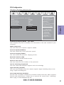
About the Setup Utility......................................................................27
The Standard Configuration........................ ...........................27
Entering the Setup Utility.......................................................27
Resetting the Default CMOS Values.....................................28
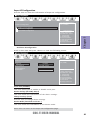
Using BIOS.........................................................................................28
BIOS Navigation Keys..............................................................29
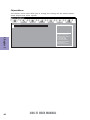
Main Menu.............................................................................30
Advanced Menu......................................................................31
Chipset Menu..........................................................................44
Tweak Menu...............................................................................47
Boot Menu...............................................................................49
Security Menu.........................................................................50
Exit Menu..................................................................................51
Updating the BIOS......................................................................52

iv
CDC-TI USER MANUAL
Chapter 4 53
Using the Motherboard Software 53
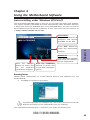
Auto-installing under Windows XP/Vista/7.................................53
Running Setup........................................................................53
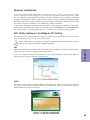
Manual Installation..........................................................................55
ECS Utility Software (Intelligent EZ Utility).....................................55
Chapter 5 57
Trouble Shooting 57
Start up problems during assembly..............................................57
Start up problems after prolong use............................................58
Maintenance and care tips..............................................................58
Basic Troubleshooting Flowchart.....................................................59

1
CDC-TI USER MANUAL
Chapter 1
Chapter 1
Introducing the Motherboard
Introduction
Thank you for choosing the CDC-TI motherboard of high performance, enhanced func-
tion. This motherboard has Onboard Cedarview CPU with a Thin Mini-ITX form factor
of 170 x 170 mm.
This motherboard is based on Intel
®®
®®
®
NM10 Express Chipset. It supports up to 4 GB of
system memory with single channel DDR3 SO-DIMM 1066/800 MHz. One optional
PCI Express x1 slot is supported. In addition, two mini PCI Express x1 slots are for
extending usage (one supports half-card, the other supports full-card.).
It implements an EHCI compliant interface that provides four USB 2.0 ports (two USB
2.0 ports at the rear panel and one USB 2.0 header supports additional two USB 2.0
ports).
The motherboard is equipped with a full set of I/O ports in the rear panel, including
one DC-IN port, one VGA port, one HDMI port, one RJ45 LAN connector, two USB 2.0
ports, and audio jacks for microphone and line-out.
In addition, this motherboard supports two SATA 3.0Gb/s connnectors for expan-
sion.
Your motherboard package ships with the following items:
Package Contents
CDC-TI Motherboard
Quick Installation Guide
User Manual
DVD
I/O Shield
2 SATA 3.0Gb/s Cables
The package contents above are for reference only, please take the actual
package items as standard.

Chapter 1
2
CDC-TI USER MANUAL
CPU
Specifications
• Intel
®
NM10 ChipsetChipset
• Singel channel DDR3 SO-DIMM memory architecture
• 2 x 204-pin DDR3 SO-DIMM sockets support up to 4 GB
• Supports DDR3 1066/800 MHz DDR3 SDRAM
Memory
• 1 x PCI Express x1 slot (Optional)
• 2 x mini PCI Express x1 Gen2 slots
(one supports half-card, the other supports full-card.)
• Supported by Intel
®
NM10 Express Chipset
- 2 x Serial ATA 3.0Gb/s devices
Expansion
Slots
Storage
• 1 x 19V DC-IN port
• 1 x D-Sub port (VGA)
• 1 x HDMI port
• 2 x USB 2.0 ports
• 1 x RJ45 LAN connector
• 1 x Audio port (1x Line out, 1x Mic in Rear)
Rear Panel I/O
LAN • Realtek 8111E Gigabit Lan (Co-lay Realtek 8105E)
- 10/100/1000 Fast Ethernet Controller
- Wake-on-LAN and remote wake-up support
• Intel
®
Onboard Cedarview CPU
• Intel FMB 10W
Note: Please go to ECS website for the latest CPU support list.
Note: Please go to ECS website for the latest Memory support list.
• 2 x 4-pin SYS_FAN connector with smart fan
• 1 x USB 2.0 header supports additional two USB 2.0 ports
• 2 x Serial SATA 3.0Gb/s connectors
• 1 x COM header (Optional)
• 1 x LVDS connector (Optional)
• 1 x Case open header
• 1 x SPDIF out header (Optional)
• 1 x Speaker header (Optional)
• 1 x Camera header
• 1 x Touch board header
• 1 x Card reader header
• 1 x ODD Power connector
• 1 x HDD Power connector
• 1 x Front Panel audio header
• 1 x Front Panel switch/LED header
• 1 x Parallel port header(LPT) (Optional)
• 1 x CLR_CMOS jumper
• 1 x LCD Select jumper (Optional)
Internal I/O
Connectors &
Headers
• Realtek ALC662
- 6 Channel High Definiton Audio Codec
- Compliant with HD audio specification
Audio

3
CDC-TI USER MANUAL
Chapter 1
• AMI BIOS with 32Mb SPI Flash ROM
- Supports ECS MIB III Utility
a. CPU Voltage Adjustable
b. Memory Voltage Adjustable
c. IMC Voltage Adjustable
- Supports Plug and Play, STR(S3)/STD(S4), Multi Boot
- Supports Hardware Monitor
- Supports ACPI 3.0 version & DMI
- Supports Audio, LAN, can be disabled in BIOS
- Supports ECS GUI UEFI BIOS
- Supports Graphic Over-Clocking
- Supports Dual-Monitor function
- F7 hot key for boot up devices option
- Supports Pgup clear CMOS Hotkey (Has PS2 KB Model only)
System BIOS
Form Factor
• Thin Mini-ITX Size, 170mm x 170mm
• Supports eBLU
• Supports eDLU
• Supports eSF
AP Suppport

Chapter 1
4
CDC-TI USER MANUAL
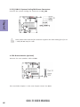
Motherboard Components
This picture may be different due to Optional Features on speccifications.

5
CDC-TI USER MANUAL
Chapter 1
Table of Motherboard Components
LABEL COMPONENTS
1. CPU Socket LGA559 socket with onboard Cedarview CPU
2. DIMM_1~2 Two 204-pin DDR3 SDRAM SO-DIMMs
3. BT Battery connector
4. SPK Buzzer header (optional)
5. CLR_CMOS Clear CMOS jumper
6. PCIE PCI Express x1 slot (optional)
7. SPEAKER 2 Channels audio speaker header (optional)
8. SPDIFO SPDIF out header (optional)
9. F_AUDIO Front panel audio header
10. CIR Consumer infrared
11. SPI_DEBUG SPI Debug header-for factory use only
12. CASE CASE open header
13. LDC Debug Card Header
Mini PCI Express x1 slot (one supports half-card, and
the other supports full-card)
15. CR Card reader header
16. ODD_PWR ODD power connector
17. HDD_PWR HDD power connector
18. F_USB Front panel USB 2.0 header
19. SATA1~2 Serial ATA 3.0 Gb/s connectors
20. CAMERA CCD header
21. TOUCH Touch board header
22. PANEL Front panel switch/LED header
23. SYS_FAN1~2 4-pin system cooling fan connector
24. COM Onboard serial port header (optional)
25. LPT Printer Header (optional)
26. DLVDS Dual Channels LVDS interface (optional)
27. BKLT_CTRL LCD panel Backlight control (optional)
28. BKLT_EN LCD panel Backlight power ON/OFF (optional)
29. LCD_SEL LCD select jumper (optional)
14. MPE1~2

Chapter 1
6
CDC-TI USER MANUAL
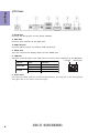
I/O Ports
1. DC-IN Port
Connect the DC-IN port to the power adapter.
2. VGA Port
Connect your monitor to the VGA port.
3. USB 2.0 Ports
Use the USB 2.0 ports to connect USB 2.0 devices.
4. HDMI Port
Y
ou can connect the display device to the HDMI port.
5. LAN Port
Connect an RJ-45 jack to the LAN port to connect your computer to the Network.
6
. Audio Ports
Use the two audio jacks to connect audio devices. The left jack is for microphone.
The right jack is for stereo line-out signal.
LAN LED Status Description
OFF
No data
Orange blinking Active
OFF
No link
Green Link
Activity LED
Link LED
LAN Port
Link LED Activity LED

Chapter 2
7
CDC-TI USER MANUAL
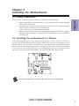
Chapter 2
Installing the Motherboard
2-1. Safety Precautions
2-2. Installing the motherboard in a Chassis
This motherboard carries a Thin Mini-ITX form factor of 170 x 170 mm. Choose a
chassis that accommodates this form factor. Make sure that the I/O template in the
chassis matches the I/O ports installed on the rear edge of the motherboard. Most
system chassis have mounting brackets installed in the chassis, which corresponds
to the holes in the motherboard. Place the motherboard over the mounting brack-
ets and secure the motherboard onto the mounting brackets with screws.
Follow these safety precautions when installing the motherboard:
• Wear a grounding strap attached to a grounded device to avoid damage
from static electricity.
• Discharge static electricity by touching the metal case of a safely grounded
object before working on the motherboard.
• Leave components in the static-proof bags.
• Always remove the AC power by unplugging the power cord from the power
outlet before installing or removing the motherboard or other hardware
components.
Do not over-tighten the screws as this can stress the motherboard.

Chapter 2
8
CDC-TI USER MANUAL
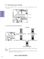
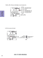
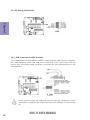
2-3. Checking Jumper Settings
This section explains how to set jumpers for correct configuration of the
motherboard.
1.When your panel connects to LVDS, please check LCD Select header setting
first.
2.Due to the differences of the panel parameters, please follow the above
illustration to place the jumper caps.
1. LCD_SEL: LCD select jumper (optional)

Chapter 2
9
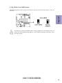
CDC-TI USER MANUAL
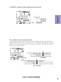
The following illustration shows the location of the motherboard jumpers. Pin 1 is
labeled.
To avoid the system instability after clearing CMOS, we recommend users to
enter the main BIOS setting page to “Load Default Settings” and then “Save
and Exit Setup”.
2. CLR_CMOS: Clear CMOS jumper

Chapter 2
10
CDC-TI USER MANUAL
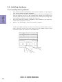
2-4. Installing Hardware
2-4-1. Installing Memory Modules
• This motherboard accommodates two memory modules. It can support
two 204-pin DDR3 SO-DIMM 1066/800.
• Do not remove any memory module from its antistatic packaging until
you are ready to install it on the motherboard. Handle the modules only
by their edges. Do not touch the components or metal parts. Always wear
a grounding strap when you handle the modules.
• You must install one module in DIMM1 or two modules in the two slots.
Total memory capacity is 4 GB.
• Refer to the following to install the memory modules.
Install the DIMM module into the slot and press it firmly down until it
seats correctly. Check that the cutouts on the DIMM module edge
connector match the notches in the DIMM slot.

Chapter 2
11
CDC-TI USER MANUAL
2-4-2. Installing Add-on Cards
The slots on this motherboard are designed to hold expansion cards and connect
them to the system bus. Expansion slots are a means of adding or enhancing the
motherboard’s features and capabilities. With these efficient facilities, you can
increase the motherboard’s capabilities by adding hardware that performs tasks
that are not part of the basic system.
MPE1~2 Slots
The mini PCI Express x1 slots are for extending usage, one sup-
ports half-card, and the other supports full-card.
Before installing an add-on card, check the documentation for
the card carefully. If the card is not Plug and Play, you may have
to manually configure the card before installation.
The PCI Express x1 slot is fully compliant to the PCI Express Base
Specification revision 2.0.
PCIE Slot

Chapter 2
12
CDC-TI USER MANUAL
1 Remove a blanking plate from the system case corresponding to the slot
you are going to use.
2 Install the edge connector of the add-on card into the expansion slot.
Ensure that the edge connector is correctly seated in the slot.
3 Secure the metal bracket of the card to the system case with a screw.
1. For some add-on cards, for example graphics adapters and network adapt-
ers, you have to install drivers and software before you can begin using the
add-on card.
2. The onboard PCI interface does not support 64-bit SCSI cards.
Follow these instructions to install an add-on card:
Please refer the following illustrations to install the add-on card:
Install the LAN Card in the PCIE X1 slot

Chapter 2
13
CDC-TI USER MANUAL
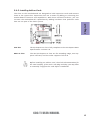
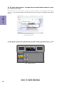
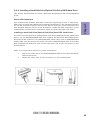
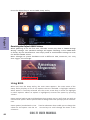
Follow these instructions to install a wireless card:
1 Remove a blanking plate from the system case, and insert the wireless
card into the MINIPCIE slot rightwards, then tighten the two screws (Please
refer to Picture 1).
2 Press the metal connector of the cable into the connector on the wireless
card. Ensure that the metal connector is correctly seated (Please refer to
Picture 2).
3 Make the other end of the cable (with a gold screw) through the upper hole
of the bracket, and tighten the antenna on to the gold screw after install-
ing a metal gasket on the screw (Please refer to Picture 3).
Picture 1 Picture 2 Picture 3

Chapter 2
14
CDC-TI USER MANUAL
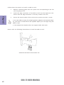
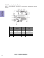
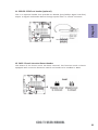
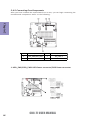
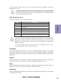
2-4-3. Connecting Optional Devices
Refer to the following for information on connecting the motherboard’s optional
devices:
No. Components No. Components
1SATA1~28 CIR
2 TOUCH/CAMERA/CR 9 SPEAKER
3COM10F_AUDIO
4 LPT 11 SPDIFO
5DLVDS12CASE
6BKLT_EN13 LDC
7BKLT_CTRL14 F_USB

Chapter 2
15
CDC-TI USER MANUAL
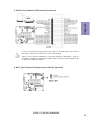
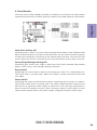
2. TOUCH/CAMERA/CR: Touch board header/CCD Header/Card reader header
SATA1~2 connectors are used to support the Serial ATA 3.0Gb/s device, simpler disk
drive cabling and easier PC assembly. It eliminates limitations of the current Paral-
lel ATA interface. But maintains register compatibility and software compatibility
with Parallel ATA.
1. SATA1~2: Serial ATA connectors
Users please note to install the card to the correct header.

Chapter 2
16
CDC-TI USER MANUAL
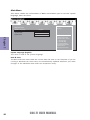
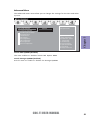
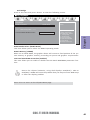
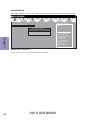
3. COM: Onboard serial port header (optional)
Connect a serial port extension bracket to this header to add a serial port to your
system.
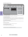
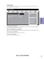
4. LPT: Onboard parallel port Header (optional)
This is a header that can be used to connect to the printer, scanner or other devices.
Page is loading ...
Page is loading ...
Page is loading ...
Page is loading ...
Page is loading ...
Page is loading ...
Page is loading ...
Page is loading ...
Page is loading ...
Page is loading ...
Page is loading ...
Page is loading ...
Page is loading ...
Page is loading ...
Page is loading ...
Page is loading ...
Page is loading ...
Page is loading ...
Page is loading ...
Page is loading ...
Page is loading ...
Page is loading ...
Page is loading ...
Page is loading ...
Page is loading ...
Page is loading ...
Page is loading ...
Page is loading ...
Page is loading ...
Page is loading ...
Page is loading ...
Page is loading ...
Page is loading ...
Page is loading ...
Page is loading ...
Page is loading ...
Page is loading ...
Page is loading ...
Page is loading ...
Page is loading ...
Page is loading ...
Page is loading ...
Page is loading ...
Page is loading ...
-
 1
1
-
 2
2
-
 3
3
-
 4
4
-
 5
5
-
 6
6
-
 7
7
-
 8
8
-
 9
9
-
 10
10
-
 11
11
-
 12
12
-
 13
13
-
 14
14
-
 15
15
-
 16
16
-
 17
17
-
 18
18
-
 19
19
-
 20
20
-
 21
21
-
 22
22
-
 23
23
-
 24
24
-
 25
25
-
 26
26
-
 27
27
-
 28
28
-
 29
29
-
 30
30
-
 31
31
-
 32
32
-
 33
33
-
 34
34
-
 35
35
-
 36
36
-
 37
37
-
 38
38
-
 39
39
-
 40
40
-
 41
41
-
 42
42
-
 43
43
-
 44
44
-
 45
45
-
 46
46
-
 47
47
-
 48
48
-
 49
49
-
 50
50
-
 51
51
-
 52
52
-
 53
53
-
 54
54
-
 55
55
-
 56
56
-
 57
57
-
 58
58
-
 59
59
-
 60
60
-
 61
61
-
 62
62
-
 63
63
-
 64
64


Ask a question and I''ll find the answer in the document
Finding information in a document is now easier with AI
Related papers
-
ECS TIGD-CI4 User manual
-
ECS BAT-I (V1.0) User manual
-
ECS CDC-I (V1.0) User manual
-
ECS CDC-M (V1.0) Specification
-
ECS G11 (V1.0) Operating instructions
-
ECS H61H-G11 (V1.0) Specification
-
ECS Z77H2-A2X Deluxe User manual
-
ECS H67H2-I (V1.1) User manual
-
ECS A55F2-M3 User manual
-
ECS P67H2-A3 (V1.0) Specification
Other documents
-
Gigabyte MQ77TN Owner's manual
-
Asus 90NB00A1-M03230 Datasheet
-
Nova RGBSP-12 User manual
-
ASROCK IMB-130 Series Owner's manual
-
SUPER MICRO Computer 5037C-T User manual
-
Supermicro SuperServer 5037C-i User manual
-
-
-
-
SUPER MICRO Computer Server 5017C-MTF User manual