BW Technologies DOCK2-2-1C1D1P-00-G User manual
- Category
- Carbon monoxide (CO) detectors
- Type
- User manual

iERP: 126103
D5617/6 [English]
© BW Technologies 2008. All rights reserved.
Automatic Test and Calibration Station
User Manual

Limited Warranty and Limitation Liability
BW Technologies LP (BW) warrants the product to be free from defects in material and workmanship under normal use and service for a period of two years, beginning on the date of
shipment to the buyer. This warranty extends only to the sale of new and unused products to the original buyer. BW’s warranty obligation is limited, at BW’s option, to refund of the purchase
price, repair or replacement of a defective product that is returned to a BW authorized service center within the warranty period. In no event shall BW’s liability hereunder exceed the
purchase price actually paid by the buyer for the Product.
This warranty does not include:
a) fuses, disposable batteries or the routine replacement of parts due to the normal wear and tear of the product arising from use;
b) any product which in BW’s opinion, has been misused, altered, neglected or damaged, by accident or abnormal conditions of operation, handling or use;
c) any damage or defects attributable to repair of the product by any person other than an authorized dealer, or the installation of unapproved parts on the product; or
The obligations set forth in this warranty are conditional on:
a) proper storage, installation, calibration, use, maintenance and compliance with the product manual instructions and any other applicable recommendations of BW;
b) the buyer promptly notifying BW of any defect and, if required, promptly making the product available for correction. No goods shall be returned to BW until receipt by the buyer of
shipping instructions from BW; and
c) the right of BW to require that the buyer provide proof of purchase such as the original invoice, bill of sale or packing slip to establish that the product is within the warranty period.
THE BUYER AGREES THAT THIS WARRANTY IS THE BUYER’S SOLE AND EXCLUSIVE REMEDY AND IS IN LIEU OF ALL OTHER WARRANTIES, EXPRESS OR IMPLIED, INCLUDING BUT NOT LIMITED TO ANY
IMPLIED WARRANTY OF MERCHANTABILITY OR FITNESS FOR A PARTICULAR PURPOSE. BW SHALL NOT BE LIABLE FOR ANY SPECIAL, INDIRECT, INCIDENTAL, OR BASED ON CONTRACT, TORT OR RELIANCE
OR ANY OTHER THEORY.
Since some countries or states do not allow limitation of the term of an implied warranty, or exclusion or limitation of incidental or consequential damages, the limitations and exclusions of
this warranty may not apply to every buyer. If any provision of this warranty is held invalid or unenforceable by a court of competent jurisdiction, such holding will not affect the validity or
enforceability of any other provision.
BW Technologies by Honeywell BW Technologies by Honeywell BW Technologies by Honeywell
Corporate Headquarters America Europe
2840 - 2nd Ave. SE 3279 West Pioneer Parkway 5 Canada Close
Calgary, AB Arlington, TX Banbury, Oxfordshire
Canada T2A 7X9 USA 76013 United Kingdom OX16 2RT

i
Table of Contents
Table Page
Limited Warranty and Limitation Liability ........................................................................................................................ 0
Introduction......................................................................................................................................................................... 1
Contacting BW Technologies by Honeywell.................................................................................................................... 2
Safety Information - Read First.......................................................................................................................................... 2
Getting Started.................................................................................................................................................................... 5
MicroDock II Base Station and Docking Modules............................................................................................................ 6
Parts of the MicroDock II Base Station and Docking Module .......................................................................................... 7
Display Elements ................................................................................................................................................................ 8
Pushbuttons........................................................................................................................................................................ 8
Docking Module Pushbuttons.......................................................................................................................................... 8
Base Station Pushbuttons ............................................................................................................................................... 9
Installation......................................................................................................................................................................... 10
Battery Installation ......................................................................................................................................................... 11
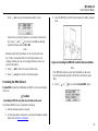
Inserting the GasAlertClip Extreme and the GasAlert Extreme..................................................................................... 12
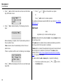
Inserting the GasAlertMicro ........................................................................................................................................... 14
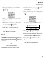
Inserting the GasAlertMicro 5/PID/IR............................................................................................................................. 16
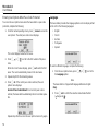
Inserting the GasAlertMicro 5/PID/IR Battery Pack.................................................................................................. 18
Inserting the GasAlertMicroClip..................................................................................................................................... 20
Inserting the GasAlertMax XT........................................................................................................................................ 22
Inserting the GasAlertQuattro........................................................................................................................................ 24
Inserting the GasAlertQuattro Battery Pack ............................................................................................................. 25
Adding Another Docking Module.................................................................................................................................... 27
Initializing the New Docking Module.............................................................................................................................. 31

MicroDock II
User Manual
Title Page
ii
Defining Pump Speed....................................................................................................................................................31
Mounting the MicroDock II ...............................................................................................................................................32
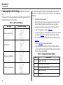
Changing Dip Switch Settings
(GasAlertClip Extreme only) ....................................................................................................................34
Using the Base Station.....................................................................................................................................................37
Confirming Inlet Setup ...................................................................................................................................................37
Activating the Base Station............................................................................................................................................37
Self-Test.........................................................................................................................................................................37
Deactivating the Base Station........................................................................................................................................38
User Options Menu ...........................................................................................................................................................39
Time/Date ......................................................................................................................................................................39
Inlet Setup......................................................................................................................................................................40
Gas Type ..................................................................................................................................................................41
Gas Concentration Level ..........................................................................................................................................43
Gas Cylinder Lot # Field ...........................................................................................................................................44
Pump Setup ...................................................................................................................................................................45
Contrast .........................................................................................................................................................................45
Backlight ........................................................................................................................................................................46
About..............................................................................................................................................................................46
Formatting the MMC/SD Card .......................................................................................................................................47
Inlet Select .....................................................................................................................................................................48
Pass Code .....................................................................................................................................................................49
Entering User Options When Pass Code Protected.................................................................................................50
Language.......................................................................................................................................................................50
Results History..................................................................................................................................................................51
Reconfiguring the Detector
(not applicable to the GasAlertClip Extreme)................................................................................................52
Gas Conflicts.....................................................................................................................................................................54
Abort Option...................................................................................................................................................................55

iii
MicroDock II
User Manual
Title Page
Conflicts .........................................................................................................................................................................55
Base Station Selects the Gas Inlet ...........................................................................................................................56
User Selects Gas Inlet..............................................................................................................................................56
Not Found ......................................................................................................................................................................57
Accessing the MMC/SD Card During a Test...................................................................................................................58
Order of Gases Applied for Bump Tests and Calibrations............................................................................................59
Bump Test..........................................................................................................................................................................62
Bump Test Results.........................................................................................................................................................65
Bump Pass ...............................................................................................................................................................65
Bump Fail..................................................................................................................................................................65
Incorrect Inlet Setup..................................................................................................................................................66
Sensor Disabled .......................................................................................................................................................66
Calibration .........................................................................................................................................................................67
Guidelines......................................................................................................................................................................67
Calibration Procedure
(All models excluding the GasAlertClip Extreme)..................................................................................68
GasAlertMicro 5 IR with CO
2
Sensor........................................................................................................................69
Calibration Results.........................................................................................................................................................70
Calibration Pass........................................................................................................................................................70
Calibration Fail..........................................................................................................................................................70
Incorrect Inlet Setup..................................................................................................................................................71
Sensor Disabled .......................................................................................................................................................71
Data Transfer
(GasAlert Extreme, GasAlertMicroClip, GasAlertMax XT, and GasAlertQuattro only) .............................................................72
Transferring Datalogs ....................................................................................................................................................72
Maximum Datalog Storage Capacity ........................................................................................................................73
Automatic Datalog Download
(GasAlertMicroClip, GasAlertMax XT, and GasAlertQuattro only)..........................................................73
Using the IR Link ......................................................................................................................................................73
Using the MicroDock II..............................................................................................................................................73

MicroDock II
User Manual
Title Page
iv
Base Station MMC/SD Card..............................................................................................................................................75
Event Logging................................................................................................................................................................75
Inserting/Replacing a MMC/SD Card.............................................................................................................................76
Accessing Test Results..................................................................................................................................................76
PC Requirements .....................................................................................................................................................76
Charging the Battery Pack (Excluding GasAlert Extreme and GasAlertClip Extreme)..............................................77
Charger/Battery Pack Guidelines...................................................................................................................................77
Charging Different Detectors Together..........................................................................................................................77
Charging Procedure.......................................................................................................................................................78
Maintenance ......................................................................................................................................................................79
Battery Pack Storage ....................................................................................................................................................79
GasAlertMicro and GasAlertMicro 5/PID/IR..............................................................................................................79
GasAlertMicroClip.....................................................................................................................................................79
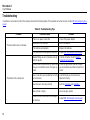
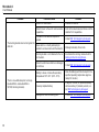
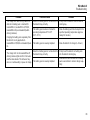
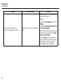
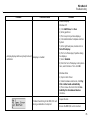
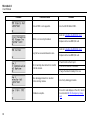
Troubleshooting................................................................................................................................................................80
Replacement Parts and Accessories ..............................................................................................................................87
Specifications....................................................................................................................................................................88
Charger Specifications...................................................................................................................................................89

v
List of Tables
Title Figure Page
1. International Symbols........................................................................................................................................... 4
2. The MicroDock II Base Station and Docking Module........................................................................................... 7
3. Display Elements ................................................................................................................................................. 8
4. Docking Module Pushbuttons............................................................................................................................... 8
5. Base Station Pushbuttons.................................................................................................................................... 9
6. Base Station Connections.................................................................................................................................. 10
7. Inserting the GasAlertClip Extreme and the GasAlert Extreme.......................................................................... 12
8. Inserting the GasAlertMicro................................................................................................................................ 14
9. Inserting the GasAlertMicro 5/PID/IR ................................................................................................................. 17
10. Inserting the GasAlertMicroClip.......................................................................................................................... 20
11. Inserting the GasAlertMax XT ............................................................................................................................ 22
12. Inserting the GasAlertQuattro............................................................................................................................. 24
13. Torque Specifications......................................................................................................................................... 27
14. Adding Another Docking Module........................................................................................................................ 27
15. Mounting the MicroDock II.................................................................................................................................. 33
16. Dip Switch Settings ............................................................................................................................................ 34
17. Changing Dip Switch Settings............................................................................................................................ 34
18. Inlets 2-5 – Available Gas Types........................................................................................................................ 41
19. Gas Type Application Table ............................................................................................................................... 60
20. Gas Application Rules........................................................................................................................................ 61
21. Charger Status LED ........................................................................................................................................... 78
22. Troubleshooting Tips ......................................................................................................................................... 80
23. Replacement Parts and Accessories ................................................................................................................. 87

MicroDock II
User Manual
vi

vii
List of Figures
Figure Title Page
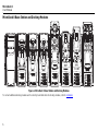
1. MicroDock II Base Station and Docking Modules................................................................................................. 6
2. The MicroDock II Base Station and Docking Module........................................................................................... 7
3. Base Station Pushbuttons.................................................................................................................................... 9
4. Base Station Connections.................................................................................................................................. 10
5. Inserting the GasAlertClip Extreme and the GasAlert Extreme.......................................................................... 12
6. Inserting the GasAlertMicro................................................................................................................................ 14
7. Inserting the GasAlertMicro 5/PID/IR ................................................................................................................. 16
8. Removing the Diffusion Adapter......................................................................................................................... 17
9. Removing the Micro 5/PID/IR Lithium Battery Pack........................................................................................... 18
10. Inserting the GasAlertMicroClip.......................................................................................................................... 20
11. Inserting the GasAlertMax XT ............................................................................................................................ 22
12. Inserting the GasAlertQuattro............................................................................................................................. 24
13. Removing the GasAlertQuattro Battery Pack..................................................................................................... 25
14. Adding Another Docking Module (Front View) ................................................................................................... 28
15. Adding Another Docking Module (Back View).................................................................................................... 29
16. Attaching Back Cover Plate (Back View)............................................................................................................ 30
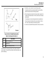
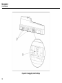
17. Attaching the Wall Mounting Plate ..................................................................................................................... 32
18. Parts of the Wall Mounting Plate........................................................................................................................ 33
19. Detaching the GasAlertClip Extreme Module..................................................................................................... 35
20. Changing Dip Switch Settings............................................................................................................................ 36
21. Inserting the MMC/SD Card into the Base Station............................................................................................. 47
22. Load Configuration File Dialog Box.................................................................................................................... 73
23. Save Configuration Dialog Box .......................................................................................................................... 74

viii
MicroDock II
User Manual
24. Save to MicroDock(s) Dialog Box.......................................................................................................................74
25. Replacing a MMC/SD Card ................................................................................................................................76

1
MicroDock II
Introduction
a Warning
To ensure personal safety, read the Safety Information before
using the MicroDock II Base Station.
The MicroDock II Automatic Test and Calibration Station (“the base sta-
tion”) provides automated calibration and bump testing for
• GasAlertClip Extreme,
• GasAlert Extreme,
•GasAlertMicro,
• GasAlertMicro 5,
• GasAlertMicro 5 PID,
• GasAlertMicro 5 IR,
• GasAlertMicroClip,
• GasAlertMax XT, and
• GasAlertQuattro detectors.
The base station also provides data transfer for
• GasAlert Extreme,
• GasAlertMicroClip,
• GasAlertMax XT, and
• GasAlertQuattro detectors.
A maximum of 8 modules can be connected to the base station.
Note
A maximum of six charging plus two non-charging modules
can be connected to the base station.
Refer to Charging the Battery Pack (Excluding GasAlert Extreme and
GasAlertClip Extreme).

MicroDock II
User Manual
2
Contacting BW Technologies by Honeywell
To contact BW Technologies by Honeywell, call:
USA: 1-888-749-8878
Canada: 1-800-663-4164
Europe: +44 (0) 1295 700300
Other countries: +1-403-248-9226
Address correspondence to:
BW Technologies by Honeywell
2840 – 2 Avenue S.E.
Calgary, AB T2A 7X9
CANADA
Email us at: info@gasmonitors.com
Visit BW Technologies by Honeywell’s website at: www.gasmonitors.com
ISO 9001
Safety Information - Read First
Use the base station only as specified in this manual.
International symbols on the base station and in this manual are
explained in Table 1.
Read the Caution statements on the following pages before using the
base station.
ec Caution
This instrument contains batteries. Do not mix with the solid waste
stream. Spent batteries should be disposed of by a qualified
recycler or hazardous materials handler.

3
MicroDock II
Safety Information - Read First
a Cautions
MicroDock ll base station
• If the base station is damaged or parts are missing, contact BW Technologies by Honeywell
immediately.
• The base station must be used only in an area that is free of hazardous gas. Do not use the base station in a hazardous
area. Failure to adhere to this caution can lead to fire and/or explosion.
• This equipment uses potentially harmful gas for calibrations. The base station must be attached to a venting system or
be used in a well-ventilated area.
• Do not calibrate the detector during or immediately after charging is complete.
• Perform calibrations and bump tests only in a safe area that is free of hazardous gas, in an atmosphere of 20.9% oxy-
gen.
• The maximum recommended exhaust line length is 50 ft. (15.24 m).
• Ensure that the inlet filter is clean.
• Ensure that all gas cylinders contain enough gas.
• Ensure the exhaust line is not connected to a negative pressure system.
• A demand flow regulator must be used with all gas cylinder connections. Input pressure not to exceed 10 psi.
• Do not expose the base station to electrical shock or severe continuous mechanical shock.
• The base station warranty will be void if the unit is disassembled, adjusted, or serviced by non-BW Technologies by
Honeywell personnel.
• Do not immerse the base station in liquids.
GasAlertMicro, GasAlertMicro 5/PID/IR, GasAlertMicroClip, GasAlertMax XT, and GasAlertQuattro Chargers
• If the charger is damaged or parts are missing, contact BW Technologies by Honeywell
immediately.
• Do not change or charge the batteries in a hazardous location. Do not use the charger in a hazardous location. Failure
to adhere to these cautions can lead to fire and/or explosion.
• Read and adhere to all instructions and cautions that are provided with the charger. Failure to do so can result in fire,
electric shock, personal injury, and/or property damage.

4
MicroDock II
User Manual
a Cautions
Table 1. International Symbols
• Use only BW approved batteries; do not use alkaline or other rechargeable batteries with this charger.
• For indoor use only.
• Do not immerse the charger in liquids.
• Do not expose the charger to electrical shock or severe continuous mechanical shock.
• Ensure the detector battery pack is locked in place before operating the detector.
• To eliminate the risk of electrical shock, disconnect and deactivate the charger when cleaning or performing mainte-
nance.
• Avoid touching the charger and detector contact pins.
• Substitution of components may impair Intrinsic Safety of the detector under charge.
• Do not charge the battery pack with any other charger.
• Do not attempt to disassemble, adjust, or service the charger unless instructions are provided to perform a procedure,
or a part is listed as a replacement part in the user manual. Use only BW Technologies replacement parts. Refer to
Replacement Parts and Accessories
.
• The charger warranty will be void if a customer, personnel, or third parties damage the charger during repair attempts.
Any non-BW Technologies by Honeywell service/repair attempts will void this warranty.
Symbol Description
n
Approved to both U.S. and Canadian Standards by CSA International
X
Conforms to European Union Directives

5
MicroDock II
Getting Started
Getting Started
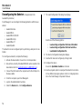
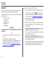
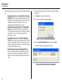
Confirm that the items listed below are included with the base station. If
the base station is damaged or parts are missing, contact the place of
purchase immediately.
• Batteries (four replaceable C-cell alkaline batteries)
• 128 MB Delkin MultiMediaCard (MMC) inserted
• USB cable
• Two to four calibration gas hoses (depending upon order at the
time of purchase) with quick connect fittings
• Inlet filter assembly
• Power adapter
• Charger adapter (charger models only)
• CD: MicroDock II User Manual and MicroDock II Quick Refer-
ence Guide translations
• MicroDock II Quick Reference Guide
• Fleet Manager II CD ROM
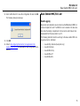
Note
A standard MicroDock II base station is shipped with two inlets.
A maximum of four calibration gas inlets can be included if
specified by the user before purchasing.
To order replacement parts, refer to Replacement Parts and Accesso-
ries.
For information regarding the operations and functions of the base sta-
tion, refer to the following figures and tables.
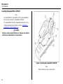
• Figure 1. MicroDock II Base Station and Docking Modules
• Figure 2. and Table 2. The MicroDock II Base Station and Dock-
ing Module
(describes the base station)
• Table 3. Display Elements
(describes the base station LCD icons)
• Table 4. Docking Module Pushbuttons
• Figure 3. and Table 5. Base Station Pushbuttons
• Figure 4. and Table 6. Base Station Connections


7
MicroDock II
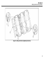
MicroDock II Base Station and Docking Modules
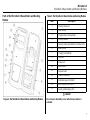
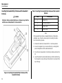
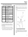
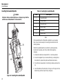
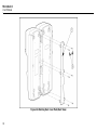
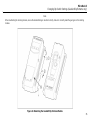
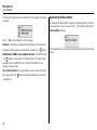
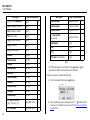
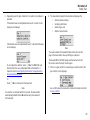
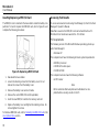
Parts of the MicroDock II Base Station and Docking
Module
Figure 2. The MicroDock II Base Station and Docking Module
Table 2. The MicroDock II Base Station and Docking Module
a Caution
Do not remove the battery cover while the base station is
activated.
Item Description
1
Docking module lid
2
Detector bay
3
Charger status LED (optional)
4
Docking module
5
Docking module pushbuttons and status LEDs
6
Battery cover
7
Charger port (optional)
8
USB port
9
Power port
10
Base station
11
Exhaust outlet
12
Station pushbuttons
13
Calibration gas inlet (inlet 2)
14
Zero air/purge inlet (inlet 1)
15
Liquid crystal display (LCD)

MicroDock II
User Manual
8
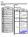
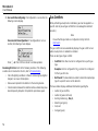
Display Elements
Table 3. Display Elements
* If powering the base station with batteries.
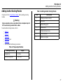
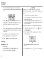
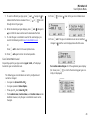
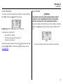
Pushbuttons
Docking Module Pushbuttons
Table 4. Docking Module Pushbuttons
Icon Description
AC power
Batteries charged*
Batteries half-charged*
Batteries at low level*
MMC or SD card
MMC or SD card not inserted
Test pass
Test fail
Cursor and sensor disabled
Scroll up
Scroll down
Selection arrow
Selected to be modified
Pass code protected
Pushbutton Description
C BUMP CHECK
To bump test a detector, press
C BUMP
CHECK.
After connecting a new docking module,
press and hold
C BUMP CHECK to
send a confirmation signal back to the
base station.
C CALIBRATION
To calibrate a detector, press
C CALI-
BRATION (all models excluding
GasAlertClip Extreme).
C DATA TRANSFER
To transfer datalog/event log information
from a detector, press
C DATA TRANS-
FER. (GasAlert Extreme,
GasAlertMicroClip, GasAlertMax XT, and
GasAlertQuattro only).
The Automatic Datalog Download option
is available for the GasAlertMicroClip,
GasAlertMax XT, and GasAlertQuattro
docking modules only. For more informa-
tion, refer to Automatic Datalog Down-
load (GasAlertMicroClip, GasAlertMax
XT, and GasAlertQuattro only).

9
MicroDock II
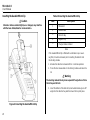
Pushbuttons
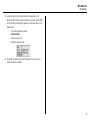
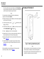
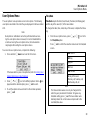
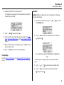
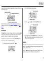
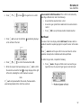
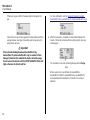
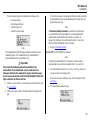
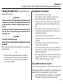
Base Station Pushbuttons
Figure 3. Base Station Pushbuttons
The base station pushbuttons activate, deactivate, scroll, select options,
and perform functions.
Table 5. Base Station Pushbuttons
Item Description
1
• Activate the base station
•Select menu to access the user options
• Select to scroll to different user options or
to other functions/selections within a user
option
•Select OK
2
•Select log to view the results history log
•Select sel to select an option
• Access a modifiable field
3
•Select exit to exit from a modifiable option
•Select exit from the user options menu to
enter normal operation
4
• Deactivate the base station
• Select to scroll to different user options or
to other functions/selections within a user
option

MicroDock II
User Manual
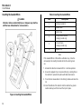
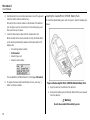
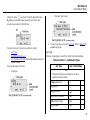
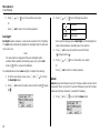
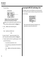
10
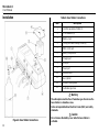
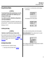
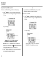
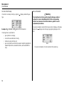
Installation
Figure 4. Base Station Connections
Table 6. Base Station Connections
a Warning
The atmosphere must be free of hazardous gas. Do not use the
base station in a hazardous area.
Follow all required National Electrical Codes (NEC) and safety
standards.
a Caution
Do not remove the battery cover while the base station is
activated.
Item Description
1
Inlet filter assembly (PURGE 1)
2
C-cell batteries (4)
3
Battery cover
4
Phillips pan head retaining screws (2)
5
MMC or SD card
6
Battery compartment
7
Charger port
8
USB port
9
Power port
10
Exhaust outlet
11
Gas cylinder
12
Demand flow regulator
13
Calibration gas hose
Page is loading ...
Page is loading ...
Page is loading ...
Page is loading ...
Page is loading ...
Page is loading ...
Page is loading ...
Page is loading ...
Page is loading ...
Page is loading ...
Page is loading ...
Page is loading ...
Page is loading ...
Page is loading ...
Page is loading ...
Page is loading ...
Page is loading ...
Page is loading ...
Page is loading ...
Page is loading ...
Page is loading ...
Page is loading ...
Page is loading ...
Page is loading ...
Page is loading ...
Page is loading ...
Page is loading ...
Page is loading ...
Page is loading ...
Page is loading ...
Page is loading ...
Page is loading ...
Page is loading ...
Page is loading ...
Page is loading ...
Page is loading ...
Page is loading ...
Page is loading ...
Page is loading ...
Page is loading ...
Page is loading ...
Page is loading ...
Page is loading ...
Page is loading ...
Page is loading ...
Page is loading ...
Page is loading ...
Page is loading ...
Page is loading ...
Page is loading ...
Page is loading ...
Page is loading ...
Page is loading ...
Page is loading ...
Page is loading ...
Page is loading ...
Page is loading ...
Page is loading ...
Page is loading ...
Page is loading ...
Page is loading ...
Page is loading ...
Page is loading ...
Page is loading ...
Page is loading ...
Page is loading ...
Page is loading ...
Page is loading ...
Page is loading ...
Page is loading ...
Page is loading ...
Page is loading ...
Page is loading ...
Page is loading ...
Page is loading ...
Page is loading ...
Page is loading ...
Page is loading ...
Page is loading ...
Page is loading ...
Page is loading ...
-
 1
1
-
 2
2
-
 3
3
-
 4
4
-
 5
5
-
 6
6
-
 7
7
-
 8
8
-
 9
9
-
 10
10
-
 11
11
-
 12
12
-
 13
13
-
 14
14
-
 15
15
-
 16
16
-
 17
17
-
 18
18
-
 19
19
-
 20
20
-
 21
21
-
 22
22
-
 23
23
-
 24
24
-
 25
25
-
 26
26
-
 27
27
-
 28
28
-
 29
29
-
 30
30
-
 31
31
-
 32
32
-
 33
33
-
 34
34
-
 35
35
-
 36
36
-
 37
37
-
 38
38
-
 39
39
-
 40
40
-
 41
41
-
 42
42
-
 43
43
-
 44
44
-
 45
45
-
 46
46
-
 47
47
-
 48
48
-
 49
49
-
 50
50
-
 51
51
-
 52
52
-
 53
53
-
 54
54
-
 55
55
-
 56
56
-
 57
57
-
 58
58
-
 59
59
-
 60
60
-
 61
61
-
 62
62
-
 63
63
-
 64
64
-
 65
65
-
 66
66
-
 67
67
-
 68
68
-
 69
69
-
 70
70
-
 71
71
-
 72
72
-
 73
73
-
 74
74
-
 75
75
-
 76
76
-
 77
77
-
 78
78
-
 79
79
-
 80
80
-
 81
81
-
 82
82
-
 83
83
-
 84
84
-
 85
85
-
 86
86
-
 87
87
-
 88
88
-
 89
89
-
 90
90
-
 91
91
-
 92
92
-
 93
93
-
 94
94
-
 95
95
-
 96
96
-
 97
97
-
 98
98
-
 99
99
-
 100
100
-
 101
101


BW Technologies DOCK2-2-1C1D1P-00-G User manual
- Category
- Carbon monoxide (CO) detectors
- Type
- User manual
Ask a question and I''ll find the answer in the document
Finding information in a document is now easier with AI
Related papers
-
BW Technologies DOCK2-3-1P-00-G Reference guide
-
-
-
-
BW Technologies XXYY-MC2 Technical Reference
-
-
-
-
-
Other documents
-
 Gas Clip Technologies Multi Gas Clip Simple Plus Portable Gas Detectors User guide
-
 Gas Clip -MGC-S Multi Gas Clip Simple User guide
-
Honeywell PHD6 Quick Reference Manual
-
 Hi-Capacity CH-5901 User manual
-
Honeywell BW Ultra Quick Reference Manual
-
AUTO METER AC-90 User manual
-
Gas Clip Technologies MGC-IR-PUMP User manual
-
Myfox TA4010 User manual
-
Honeywell BW Max XT ll Multi Gas Detector User guide
-
Gas Clip Technologies MGC User guide


