Mitsubishi VS-50805 Owner's manual
- Category
- Projection TVs
- Type
- Owner's manual

MITSUBISHI
THE BIG SCREEN COMPANY TM

CAUTION: TO REDUCE THE RISK OF ELECTRIC SHOCK, DO NOT REMOVE COVER
(OR BACK).
NO USER-SERVlCEABLE PARTS INSIDE.
REFER SERVICING TO QUALIFIED SERVICE PERSONNEL.
RISKOF ELECTRICSHOCK
DO NOT OPEN
/_The lightning flash with arrowhead symbol within an equilateral triangle is intended to alertthe user to the presence of uninsulated"dangerous voltage within the products enclosure
that may be of sufficient magnitude to constitute a risk of electric shock.
//_ The exclamation point within an equilateral triangle is intended to alert the user to thepresence of important operating and maintenance (servicing) instructions in the literature
accompanying the appliance.
Warning: To avoid permanently imprinting a fixed imageonto yourTV screen,pleasedo not displaythe same
stationary imageson the screen for more than 15%of your total TV viewing in one week. Examplesof stationary
imagesare letterbox top/bottom barsfrom DVD disc or other video sources,side barswhen showing standardTV
pictures on widescreenTV's,stock market reports, video game patterns, station logs,web sitesor stationary com-
puter images. Suchpatterns can unevenly agethe picture tubes causing permanent damageto theTV. Pleasesee
page56 for a detailed explanation.
Note: This equipment has been tested and found to comply with the limits for a Class B digital
device, pursuant to part 15of the FCC Rules. These limits are designed to provide reasonable
protection against harmful interference in a residential installation. This equipment generates, uses
and can radiate radio frequency energy and, if not installed and used in accordance with the instruc-
tions, may cause harmful interference to radio communications. However, there is no guarantee that
interference will not occur in a particular installation. If this equipment does cause harmful interfer-
ence to radio or television reception, which can be determined by turning the equipment off and on,
the user is encouraged to try to correct the interference by one or more of the following measures:
• Reorient or reJocate the receiving antenna
• Increase the separation between the equipment and receiver
• Connect the equipment into an outlet on a circuit different from
that to which the receiver is connected
• Consult the dealer or an experienced radio/TV technician for help
Changes or modifications not expressly approved by Mitsubishi could void the user's authority to operate
this equipment.
WARNING:
TO REDUCETHE RISKOF FIREOR ELECTRIC SHOCK, DO NOT EXPOSETHISAPPLIANCETO RAIN OR
MOISTURE.
CAUTION:
TO PREVENTELECTRICSHOCK, MATCH WIDE BLADE OF PLUGTO WIDE SLOT,FULLYINSERT.
NOTE TO CATV SYSTEM INSTALLER:
THIS REMINDER ISPROVIDEDTO CALLTHE CATV SYSTEMINSTALLER'SATTENTION TOARTICLE 820-40 OF
THE NEC THAT PROVIDESGUIDELINES FOR PROPERGROUNDING AND, IN PARTICULAR,SPECIFIESTHAT
THE CABLE GROUND SHALL BECONNECTEDTOTHE GROUNDING SYSTEMOFTHE BUILDING,AS CLOSE
TOTHE POINT OF CABLE ENTRYAS PRACTICAL.

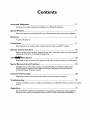
Contents
Important Safeguards 5
Instructions on safety and proper handlingof your Mitsubishi television
Special Features 7
Distinctive features, items included with your Mitsubishi television and hookup guidelines
Shortcuts 8
A quick reference list
Connections 9
Basichookups to an antenna, cable,components, IR emitter and HDTV receiver
Remote Control Functions 18
Features of the remote control, programming to work with other audio and video products,
explanation of buttons, controlling the sleep timer
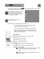
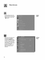
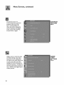
The I_l_Menu System 25
Explanation of the on-screen menu system and all menu screens and how to use the menus
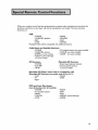
Special Remote Control Functions 59
Using the remote with other products, using the PIP (Picture-in-Picture), Side-by-side
and POP (Picture-outside-Picture) features, Formats, Mitsubishi's Active AV Network
and Home Theater IR system control
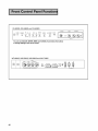
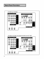
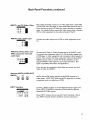
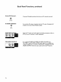
Control Panel Functions 68
Explanation of the front control panel buttons and the back panel terminals
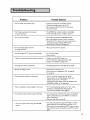
Troubleshooting 73
Common problems, notes on caring and cleaningfor your Mitsubishi television and how to obtain
service
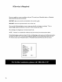
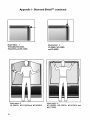
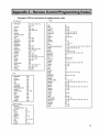
Appendices 77
Diamond ShieldTM removal and installation, remote control programming codes, bypassing
the parent lock, INPUT-3 component video and HDTV video connection compatibility


Please read all these instructions regarding your television set and retain for future refer-
ence. Follow all warnings and instructions marked on the television.
I. Read, Retain and Follow Instructions
Readaltsafety and operating instructionsbefore operating the appliance. Retain the safety and operating
instructionsfor future reference. Follow all operating and use instructions.
2. Heed Warnings
Adhere to altwarnings on the applianceand inthe operating instructions.
3. Cleaning
Unplug this TV receiver from the wall outlet before cleaning. Do not useliquid or aerosol cleaners.
Cleaners can permanently damagethe cabinet or screen. Usea damp cloth for cleaning.
4. Attachments and Equipment
Never add anyattachments and/orequipment without approval of the manufacturer assuch additions
may result in the risk of fire, electric shock or other personal injury.
5. Water and Moisture
Do not usethis TV receiver where contact with or immersionin water ispossible. Do not usenear bath
tubs,wash bowls, kitchen sinks,laundry tubs, swimming pools, etc.
@
6. Accessories
Do not placethis TV receiver on an unstable cart, stand,tripod, bracket, or table. TheTV receiver may
fall,causingserious injuryto a child or adult,and serious damageto the appliance. Use only
with acart, stand,tripod, bracket, or table recommended bythe manufacturer,or sold
with the TV receiver. Any mounting of the applianceshould follow the manufacturer's
instructions,and should use a mounting accessory recommended bythe manufacturer.
An applianceand cart combination should be movedwith care. Quick stops, excessive
force, and unevensurfaces maycausethe applianceandcart combination to overturn.
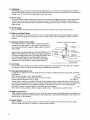
7. Ventilation
Slots and openings inthe cabinet are provided for ventilation and to ensure reliable operation of theTV
receiver andto protect it from overheating. Do not block these openings or allow them to be blocked
by placingtheTV receiver on a bed,sofa,rug,or other similar surface. Nor should it be placedover a
radiator or heat register. If the TV receiver is to be placed in a rack or bookcase,ensurethat there is
adequateventilation and that the manufacturer's instructionshavebeen adhered to.
. Power Source
ThisTV receiver should be operated only from the type of power source indicatedon the marking label.
If you are not sure of the type of power supplied to your home, consult your appliancedealeror local
power company.
.
Grounding or Polarization
ThisTV receiver isequipped with a polarized alternating current line plug havingone blade wider than
the other. This plug will fit into the power outlet only one way. If you are unable to insert the plug fully
into the outlet, try reversing the plug. If the plug should still fail to fit, contact your electrician to replace
your obsolete outlet. Do not defeat the safety purpose of the polarized plug.
I O. Power-Cord Protection
Power-supply cords should be routed so that they are not likely to be walked on or pinched by items
placed upon or against them, paying particular attention to cords at plugs, convenience receptacles, and
the point where they exit from the appliance.

I I. Lightning
For added protection for thisTV receiver during a lightningstorm, or when it isleft unattendedand unusedfor
longperiods of time, unplug it from the wait outlet and disconnect the antennaor cablesystem. This will prevent
damageto theTV receiver due to lightning and power-line surges.
12. Power Lines
An outside antenna system should not be locatedinthe vicinity of overhead power lines or other electric light
or power circuits, or where it canfall into such power linesor circuits. When installinganoutside antenna
system,extreme care should be taken to keepfrom touching such power lines or circuits ascontact with them
might be fatal.
13. Overloading
Do not overload wait outlets and extension cords asthis canresult ina risk of fire or electric shock.
14. Object and Liquid Entry
Never pushobjects of anykind into this TV receiver through openingsasthey maytouch dangerousvoltage
points or short-out parts that could result in a fire or electric shock. Never spill liquidof anykind on theTV
receiver.
15. Outdoor Antenna Grounding
If an outside antennaor cablesystem is connected to the TV
receiver,be sure the antennaor cablesystem isgrounded so as
to provide some protection againstvoltage surgesand built-up
static charges.
Section 810 of the National Electrical Code,ANSI/NFPA No. 70-
1984,provides informationwith respect to proper grounding of
the mast and supporting structure, grounding of the lead inwire
to an antennadischarge unit, size of grounding conductors,
locationof antenna dischargeunit,connection to grounding
electrodes, and requirements for the grounding electrode.
16. Servicing
EXAMPLE OF ANTENNA GROUNDING
ANTENNA
LEAD IN WkRE
GROUND CLAMP
ANTENNA
( DISCHARGE UNiT
(NEC SECTION 8_0-20)
GROUNDING
CONDUCTORS
(NEC SECTkON 8_0-21)
OUND CLAMPS
_ _"'_'_"_,_ p OWE R SERVICE GROUNDING
ELECTRODE SYSTEM
NEC ._ NATkONAL ELECTRICAL CODE (NEC ART 250, PART H)
Do not attempt to service this TV receiver yourself asopening or removing covers may expose you to danger-
ous voltage or other hazards. Refer atlservicing to qualified service personnel.
17. Damage Requiring Service
Unplug this TV receiver from the walloutlet and refer servicingto qualified service personnel under the follow-
ing conditions: (a)
When the power-supply cord or plug isdamaged. (b) If
liquid hasbeen spilled,or objects havefallen into theTV receiver. (c) If theTV
receiver hasbeen exposed to rain or water. (d) If theTV
receiver does not operate normally by following the operating instructions,adjust onty those controls that are
covered bythe operating instructionsasan improper adjustment of other controls may result in damageand witl
often require extensive work by a qualified technician to restore theTV receiver to itsnormal operation.
(e) If theTV receiver hasbeen dropped or the cabinet hasbeen damaged. (f)
When theTV receiver exhibits a distinct changein performance -- this indicatesaneedfor service.
18. Replacement Parts
When replacement parts are required, be sure the service technician hasused replacement parts specifiedby the
manufacturer or havethe samecharacteristics asthe original part. Unauthorized substitutions mayresult in fire,
electric shock or other hazards.
19. Safety Check
Upon completion of anyservice or repairs to this TV receiver,askthe service technician to perform safety
checksto determine that the TV receiver isin safeoperating condition.

0 HDTV Upgradeable - with the use of an optional HDTV receiver,
your television can display High Definition pictures
0Wide Screen Television- displays pictures in a widescreen 16:9 aspect
ratio for models WT-46805,WS-55805,WS-55905,WS-65905 andWS-73905
0Wide Screen Formats-for displaying anamorphic DVDs on models
VS-50805 and VS-60805
0 IRIS TM - room sensor that automatically adjusts brightness and contrast
0 Multibrand Remote Control - use one remote control for many
audio/video components
The following items are included with your newTV:
b 2 AAA
O batteries
Active A/V Network Cable
IR Emitter Cable
Dialnond Shiekd (may aiready be _nst akled )
The connections shown in this book are general. Cable systems as well as individual audio and/
or video components can vary from those shown here. The first diagrams show basic connec-
tions to antenna or cable systems. After you have completed these, you can then connect any
additional components (stereo, DVD, AV receiver, etc.).
IMPORTANT
To maximize your system for its best
performance, your dealer can help you
customize hookups and sell you any addi-
tional connection accessories that may be
needed for your individual equipment.

0 Connecting theTV to an antenna or wall outlet cable
0 Connecting an HD-1080 receiver - page 15
0 Remote control functions - pages 18-19
0 Menu screen summaries - pages 26-28
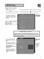
0 Setup Menu - pages 29-35
0 Setting theV-Chip parent lock - pages 44-48
0 Using PIP and POP features - page 60
0Troubleshooting- page 73
0 DVD component video and HDTV video connection
compatibility - page 83
- page 9

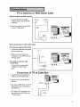
TV to Antenna or Wall Outlet Cable
Separate UHF andVHF antennas
I, Connect the UHF andVHF
antenna leads to the UHF/VHF
combiner,
2, Push the combiner onto ANT-A
on the TV back panel.
VHF A_te_na UHF Antenr_a
(Chanr_ls 2-_3) (Ch_nels 14_69)
Back SUe
TVback panel
Twin lead antenna or wall outlet cable
For antenna with twin flat leads
I. Connect the 300 ohm twin leads
to the transformer.
2. Push the 75 ohm side of the
transformer onto ANT-A on the
TV back panel.
For cable or antenna with
coaxial lead
Connect the incoming cable
to ANT-A on the TV back
panel.
30O Ohm FF_t _
lwln Le_d
Olxiona_ 30O Oh_ _o75 Ohm
M_tch_ T_ansfc_me_
TV back panel
Connection of TV to Cable Box
I. Connect the incoming cable to
ANT-A on the TV back panel.
2. Connect two coaxial cables as
follows:
• One from LOOP-OUT on theTV
back panel to IN on the back of
the cable box.
• One from OUT on the back of
the cable box to ANT-B on the
TV back panel.
TW_d¢_
mln_
9

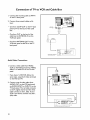
Connection of TV to VCR and Cable Box
I. Connect the incoming cable toANT-A
on theTV back panel.
2. Connect three coaxial cables as fol-
{ows:
• One from LOOP-OUT on theTV back
panel to IN on the back of the cable
box.
• One from OUT on the back of the
cable box toANTENNA IN on the
VCR back panel.
• One from ANTENNA OUT on the
VCR back panel to ANT-B on the TV
back panel.
R_ Ten_nar_
Audio Video Connections
I. Connect a video cable from VIDEO,
OUT on theVCR back panel to VIDEO,
INPUT-I or INPUT-2 on theTV back
panel.
If you have a S-VHS VCR, follow the
same steps, using the S-Video terminals
on theVCR and TV.
2. Connect a set of audio cables from
AUDIO, OUT on the VCR back panel
to AUDIO, INPUT- Ior INPUT-2 on the
TV back panel. The red cable connects
to the R (right) channel and the white
cable connects to the L (left). If your
VCR is non-stereo, connect only the L
(left) cable.
@@@@®
10

Connection of TV to VCR and Antenna or
Wall Outlet Cable
Antenna/Cable Connections
I. Connect the incoming cable to ANT-A on
theTV back panel.
2. Connect two coaxial cables as follows:
• One from LOOP-OUT on theTV back
panel to ANTENNA IN on theVCR back
panel.
• One fromVCR back panelANTENNA OUT
to ANT-B on the TV back panel.
Audio/Video Connections
I. Connect a video cable fromVIDEO, OUT
on theVCR back panel toVIDEO, INPUT- I
or INPUT-2 on the TV back panel (INPUT-
I shown).
If you have a S-VHSVCR, follow the same
steps, using the S-Video terminals on the
VCR and TV.
2. Connect a set of audio cables from AU-
DIO OUT on theVCR back panel to
AUDIO, INPUT-I or INPUT-2 on theTV
back panel. The red cable connects to the
R (right) channel and the white cable
connects to the L (left). If yourVCR is
non-stereo, only connect the L (left) cable
(Input-I shown).
.....................i
o_/o_F _t_ _t _ OFF
II

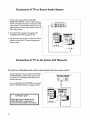
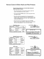
Connection of TV to Stereo Audio System
I. Connect the audio cables from AUDIO,
MONITOR OUTPUT on the TV back panel to
TV IN orAUX IN terminals on the back of the
audio system. The red cable connects to the R
(right) channel and the white cable connects to
the L (left) channel.
2, Turn off the TV'S speakers through the AV
CONNECTION Menu (pages 32-34).
3, Set the audio system's input to theTV orAUX
position to hear the TV's audio through your
stereo system.
Audio system b_ p_ne_s_a_
TV_kpan_
@@@
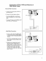
Connection of TV to the Active AJV Network
To control your Mitsubishi audio and/or video products with one remote control
Connect the A/V network cable from ACTIVE
A/V NETWORK on theTV back panel to IN
on the back of a Mitsubishi VCR that hasA/V
network terminal
Turn the ACTIVE A/V NETWORK on through
theAV CONNECTION menu (pages 32-34).
IMPORTANT
Check the Owner's Guide of your
added Mitsubishi components to
ensure the best possible connections.
TV back panel
Mitsubishi Component back panel section
12

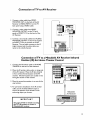
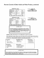
Connection of TV to AV Receiver
I, Connect a video cable fromVIDEO,
MONITOR OUT on the back of the AV
Receiver toVIDEO, INPUT-I on theTV
back panel using aVIDEO cable,
2, Connect a video cable fromVIDEO,
MONITOR OUTPUT on the TV back
panel to VIDEO TV IN on the back of the
AV Receiver,
3, Connect a set of audio cables from AUDIO,
MONITOR OUTPUT on the TV back panel
toAUDIOTV IN on the back of the AV
Receiver, The red cable connects to the R
(right) channel and the white cable con-
nects to the L (left) channel,
Connection of TV to a Mitsubishi AV Receiver Infrared
Emitter (IR) for Home Theater Control
I, Connect the IR emitter cable to IR HOME
THEATER on the back of the television,
2, Place the IR emitter cable under or along side
of theAV receiver, Place the IR lens directly
in front of the infrared location of the AV
receiver, Infrared locations are usually on the
front glass section of the receiver,
3, Place the unused transmitter in an out-of-the-
way location,
4, For permanent installation of the IR emitter
cable, use the included adhesive tape to
secure the bottom of the emitter to the
anchoring object you choose,
IMPORTANT I
See pages 67-68 for details on using I
the TV s IR emitter to control a
M tsub sh AV rece vet. I
TV back panel
Mitsubishi
AV Receiver
13

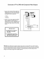
Connection of TV to DVD with Component Video Outputs
I. Connect the ComponentVideo cables from
VIDEO OUT on the back of the DVD player
to DVDVIDEO input on theTV back panel,
matching the correct components:
• YtoY,
• Cr to Cr,
• Cb to Cb,
2. Connect a set of audio cables from AUDIO
OUT on the back of the DVD player to
AUDIO, INPUT-3 on theTV back panel. The
red cable connects to the R (right) channel
and the white cable connects to the L (left)
channel.
IMPORTANT
h SeeAppendix 4 for component
video signal compatibility
information.
2. For DigitalAudio connections,
see the Owner's Guides of your
DVD Player and AV receiver.
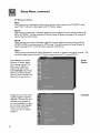
Warning: Don't displaythe samestationary imageson the screenfor more than 15%of your total TV viewing in
one week. Examplesof stationary imagesare letterbox top/bottom bars from DVD disc or other video sources,side
bars when showing standardTV pictures on widescreenTV's,stock market reports, video gamepatterns, station Iogos,
web sites or stationary computer images.Suchpatterns can unevenly agethe picture tubes causingpermanent
damageto the T_. Pleaseseepage74 for a detailed explanation.
14

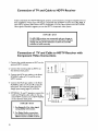
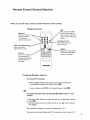
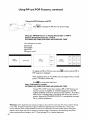
Connectors for TV and Cable to HDTV Receiver
The TV back panel has 5 RCA type connectors, for the HDTV
connection. The back panel of your HDTV receiver may use
RCA type connectors or BNC type connectors for its connec-
tion. If your HDTV receiver comes with BNC type connec-
tions, you will have to purchase BNC to RCA adaptors, to
connect theTV to the HDTV receiver. These adaptors should
be available at electronics supply stores.
BNC to Adaptol
RCA BNC Fitted to
Adaptor Connector Connection
RCA
Connec_r
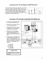
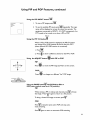
Connection of TV and Cable to Mitsubishrs HD-1080 Receiver
I. Connect the outside antenna toANT
on the optional HD-1080 receiver.
2. Connect the incoming cable toANT-A
on the television back panel.
3. Connect the HDTV cable to HDTV
CONTROL on the TV back panel and
the HDTV receiver back panel.
4. OPTIONAL: To useTV speakers,
connect the audio cables to HDTV
L(left) and R(right) AUDIO on the
HDTV receiver and the television back
panel.
5. Connect the color coded BNC cables
to HDTVVIDEO on the HDTV re-
ceiver. After fitting the BNC to RCA
adaptors onto the BNC cables, connect
them to the television back panel. The
sequence for connecting the color
cables is:
Y = green cable
Pr = red cable
Pb = blue cable
H = white cable
V = yellow cable
IIIIIIIIIIIIIIII
0111111011111111
IIIIIIIIIIIIIIII
IIIIIIIIIIIIIIII
IMPORTANT
For Digital Audio connections, see
the Owner's Guides of your HDTV
receiver.
15

Connection of TV and Cable to HDTV Receiver
Industry Standards for HDTV RGB signals systems, synchronizations and signal strengths have not
been established. These inputs will not be compatible with all HDTV receivers that offer RGB. If
your HDTV receiver offers both a HDTV component (Y,Pr,Pb) video system and a HDTV RGB
video signals, Mitsubishi suggests you use the HDTV component video system.
IMPORTANT
If a HD-1080 receiver was connected and you change to
another DTV receiver, you must turn the Power off, then
unplug and plug in the television to allow the new HD
receiver to work correctly.
Connection of TV and Cable to HDTV Receiver with
Component Video Connections
I. Connect the outside antenna to ANT on the
optional HDTV receiver.
2. Connect the incoming cable to ANT-A on
the television back panel.
3. Connect the RCA type cables or the fitted
RCA/BNC cables toY, Pr and Pb on the
HDTV receiver.
4. Connect the RCA type cables or the fitted
RCA/BNC cables toY, Pr,and Pb on theTV
back panel. You must also select the DTV
Assign Input setting (page 35) of YPrPb.
5. OPTIONAL: To useTV speakers, connect the
L(left) and R(right) audio cables to the op-
tional HDTV receiver and to HDTVAUDIO
on the television back panel.
IMPORTANT
I. SeeAppendix 4 for video signal
compatibility information.
2. For Digital Audio connections,
see the Owner's Guides of your
HDTV receiver and AV receiver.
if......................
16

Connection of TV and Cable to HDTV Receiver with
RGB Connections
I, Connect the outside antenna to
ANT on the optional HDTV re-
ceiver.
2. Connect the incoming cable to ANT-
A on the television back panel.
3. Connect the RGB cables to the
HDTV receiver and the televesion
back panel. The sequence for
connecting the cables is:
HDTV Receiver TV Back
Panel
G (green) = Y
R (red) = Pr
B (blue) = Pb
If the receiver has separate sync*,
also connect:
H (horizontal sync) = H
V (vertical sync) = V
do not connect if HDTV Receiver uses
"Sync on Green".
You must also select the DTVAssign
Input setting (page 35) of RGB.
4. OPTIONAL:To useTV speaker, connect
the L(left) and R(right) audio cables to
the optional HDTV receiver and to
HDTV AUDIO on the television back
panel.
IMPORTANT
I. SeeAppendix 4 for video signal
compatibility information.
2. For DigitalAudio connections,
see the Owner's Guides of your
HDTV receiver and AV receiver.
ROA a_C _itt_d to
A_p_r Conn_tor C0n_on
17

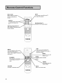
Select switch
Selects which A/V
will be controlled by the
remote
Numbers
Individually
or enter informasion into
TV
SQV (SuperQuickView TM)
Scan through a memorized lis
favorite channels
Power
/oT:ntShPeO , ;rn?dcO.forthe
QV (QuickView TM)
Switchesto last channel viewed
INPUT
(Ant-A,Ant-B, DTV, Input- I,
Input-2,1nput-3 [DVD component]
and Input-4)
CHANNEL
View channels in increasing
or decreasing
order
VOLUME
Increases or decreases so
SUB
HDTV
receiver is connected, use to enter a
subchannel number
SLEEP
Sets theTV to turn off
within 2 hours
VIDEO
y selects the Video
settings
AUDIO
- Individually selects the
Audio settings
MUTE
Turns on or off the sound
18

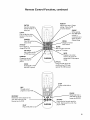
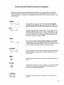
Remote Control Functions, continued
ENTER
Use after selecting a
channel number or
menu item
LIGHT
Press to light the white
buttons
control
CANCEL
Clear SQV and some_
menu entries
PIP/POP
Use to display or
change PIP or POP
PIP INPUT
Use to select the
or POP input source
FORMAT
Change the size and
shape of the main TV
picture
EXCH
Exchange PiP
and main TV picture
ADJUST
Selects menu items. Change
settings. Moves the PIP
on-screen location
MENU
on-screen
menu choices
HOME
Exit on-screen menus and
return to TV viewing
GUIDE
When optional
HD-1080 HDTV
receiver is
connected, use to
display the DTV
Channel Guide
INFO
• Displays an on-screen
summary of currentTV
settings and V-Chip program
ratings
PIP CH
Change the PIP channel, for
Ant-A, Ant-B or DTV (with
optional HD- 1080 receiver)
REC
Manually record
programs on yourVCR
REWIREV
Rewind and reverse search for the
VCR. Skip reverse for CD.
Reverse scan for DVD
PLAY
PlaysaVCR, DVD or CD
© © © (i)
© © ©
©©O
©©©_
STOP
To stop aVCR, DVD or
PAUSE
_Temporarily stops a
VCR, DVD or CD or
freezes the PIPIPOP
FFIFWD
Fast forward or forward search for
forward for a CD. Fast
play for a DVD
19

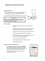
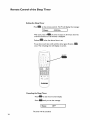
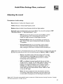
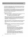
Operating Your Remote Control
Installing the batteries
I. Remove the back cover of the remote control by pushing the
tab in the direction of the arrow and sliding off the cover.
2. Load the batteries, making sure the polarities(+) and (-) are correct.
IMPORTANT
When you replace the batteries in your remote control,
the remote may return to its initial setting. You may
need to set up your remote again.
@@
For best results
Be within 20 feet of the equipment when using the remote
control
Don't press two or more buttons at the same time, unless you
are specifically instructed to do so in this owner's guide.
Don't allow the remote control to get wet or become heated.
Avoid dropping the remote control on a hard surface.
When cleaning the remote control, don't use any harsh chemi-
cals. Use only a soft, slightly moistened cloth.
Don't mix new batteries with old ones.
Don't heat, take apart, or throw batteries into a fire.
Use AAA alkaline batteries.
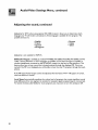
Using the remote control with yourTV
You can use your remote to control the TV, CABLE/DBS/
DTV, VCR, DVD or AUDIO. The remote has been preset
to operate theTV and other Mitsubishi products. It can be
set to control other brands of audio/video equipment.
To operate the "IV, the select switch at the top of the
remote should be set toTV.
r_l I-_
0000
000
O O O
;;;oo
20
Page is loading ...
Page is loading ...
Page is loading ...
Page is loading ...
Page is loading ...
Page is loading ...
Page is loading ...
Page is loading ...
Page is loading ...
Page is loading ...
Page is loading ...
Page is loading ...
Page is loading ...
Page is loading ...
Page is loading ...
Page is loading ...
Page is loading ...
Page is loading ...
Page is loading ...
Page is loading ...
Page is loading ...
Page is loading ...
Page is loading ...
Page is loading ...
Page is loading ...
Page is loading ...
Page is loading ...
Page is loading ...
Page is loading ...
Page is loading ...
Page is loading ...
Page is loading ...
Page is loading ...
Page is loading ...
Page is loading ...
Page is loading ...
Page is loading ...
Page is loading ...
Page is loading ...
Page is loading ...
Page is loading ...
Page is loading ...
Page is loading ...
Page is loading ...
Page is loading ...
Page is loading ...
Page is loading ...
Page is loading ...
Page is loading ...
Page is loading ...
Page is loading ...
Page is loading ...
Page is loading ...
Page is loading ...
Page is loading ...
Page is loading ...
Page is loading ...
Page is loading ...
Page is loading ...
Page is loading ...
Page is loading ...
Page is loading ...
Page is loading ...
Page is loading ...
Page is loading ...
Page is loading ...
Page is loading ...
Page is loading ...
-
 1
1
-
 2
2
-
 3
3
-
 4
4
-
 5
5
-
 6
6
-
 7
7
-
 8
8
-
 9
9
-
 10
10
-
 11
11
-
 12
12
-
 13
13
-
 14
14
-
 15
15
-
 16
16
-
 17
17
-
 18
18
-
 19
19
-
 20
20
-
 21
21
-
 22
22
-
 23
23
-
 24
24
-
 25
25
-
 26
26
-
 27
27
-
 28
28
-
 29
29
-
 30
30
-
 31
31
-
 32
32
-
 33
33
-
 34
34
-
 35
35
-
 36
36
-
 37
37
-
 38
38
-
 39
39
-
 40
40
-
 41
41
-
 42
42
-
 43
43
-
 44
44
-
 45
45
-
 46
46
-
 47
47
-
 48
48
-
 49
49
-
 50
50
-
 51
51
-
 52
52
-
 53
53
-
 54
54
-
 55
55
-
 56
56
-
 57
57
-
 58
58
-
 59
59
-
 60
60
-
 61
61
-
 62
62
-
 63
63
-
 64
64
-
 65
65
-
 66
66
-
 67
67
-
 68
68
-
 69
69
-
 70
70
-
 71
71
-
 72
72
-
 73
73
-
 74
74
-
 75
75
-
 76
76
-
 77
77
-
 78
78
-
 79
79
-
 80
80
-
 81
81
-
 82
82
-
 83
83
-
 84
84
-
 85
85
-
 86
86
-
 87
87
-
 88
88


Mitsubishi VS-50805 Owner's manual
- Category
- Projection TVs
- Type
- Owner's manual
Ask a question and I''ll find the answer in the document
Finding information in a document is now easier with AI
Related papers
-
Mitsubishi VS-45607 User manual
-
-
-
-
-
-
-
-
-
Mitsubishi LT-2220 Owner's manual
Other documents
-
 Mitsubishi Electronics WS-55905 User manual
-
Quasar SP2729 User manual
-
 Senior TV LTC3204 Owner's manual
-
 Mitsubishi Electronics HS-U778 User manual
-
ProScan Plus Silver PSVR85 User manual
-
 Mitsubishi Electronics CS-35305 User manual
-
Panasonic Car Satellite TV System CT-36DV60 User manual
-
-
-


