Page is loading ...

Owner's
Manual
Model No.
139.53962SRT
139.53975SRT
For Residential Use
Only
Caution:
Read and follow all
safety rules and
operating instructions
before first use of this
product.
Fasten the manual
near the garage door
after installation.
Complies with UL325 [11_ _
regulations effective
January 1, 1993
CRAFTSMAN®
GARAGE DOOR OPENER
112HP
• Safety Precautions
• Assembly
• Installation
• Adjustment
• Care and Maintenance
• Operation
• Troubleshooting
• Parts List
Sears, Roebuck and Co., Hoffman Estates, IL 60179 U.S.A.

Contents Page
A review of safety alert symbols................................. 2
You'll need tools.......................................................... 3
Safety information regarding garage door
locks and ropes ......................................................... 3
Testing your garage door for sticking,
binding and balance .................................................. 3
lUustration of sectional door installation .....................4
Illustration of one-piece door installation ....................5
Carton inventory .......................................................... 6
Hardware inventory ..................................................... 7
Assembly section - pages 8 - 11
Assemble the rail & install the trolley........................ 8
Fasten the railto the opener ..................................... 9
Installthe idler pulley ................................................ 9
Installchain/cable & attach the sprocketcover......10
Tighten the chain .................................................... 11
Installation section - pages 11 - 27
Installationsafety instructions................................. t 1
Determine header bracket location
Sectional door...................................................... 12
One-piece door .................................................... 13
Installthe header bracket ....................................... 14
Attach the railto header bracket ............................ 15
Positionthe opener ................................................. 16
Hang the opener ..................................................... 17
Installthe door control ............................................ 18
Contents Page
install the lightsand lenses ...................................... 19
Attach emergency release rope and handle ...........19
Electrical requirements ............................................. 20
Safety reversing sensor information ........................ 21
install the safety reversing sensor ..................... 22, 23
Fasten door bracket (sectional door) ....................... 24
Fasten door bracket (one-piece door) ..................... 25
Connect door arm to trolley (sectional door) ...........26
Connect door arm to trolley (one-piece door) ..........27
Adjustment section - pages 28 - 30
Travel limit adjustments ........................................... 28
Force adjustments .................................................... 29
Test the safety reversing sensor .............................. 30
Test the safety reverse system ............................... 30
Operation safety instructions ..................................... 31
Care of your opener ................................................... 31
Maintenance schedule ............................................... 31
Operation of your opener ........................................... 32
Receiver and remote control programming ...............33
Having a problem? ............................................... 34, 35
Repair parts, rail assembly ......................................... 36
Repair parts, installation ............................................. 36
Repair parts, opener assembly .................................. 37
Accessories ................................................................ 38
Index ........................................................................... 39
How to order repair parts ........................................... 40
Warranty ..................................................................... 40
Start by Reviewing these Important Safety Alert Symbols
When you see these Safety Symbols on the following pages, they will alert you to the possibility of
serious injury or death if you do not comply with the corresponding instructions. The hazard may
come from something mechanical or from electric shock. Read the instructions carefully.
Mechanical Electrical
When you see this Safety Symbol on the following pages, it will alert you to the possibility of damage
to your garage door and/or the garage door opener if you do not comply with the corresponding
instructions. Read the instructions carefully.
This garage door opener is designed and tested to offer safe service provided it is installed, operated,
maintained and tested in strict a_cordance with the safety instructions contained in this manual.

You'll Need Tools
During assembly, installation and adjustment of the opener, instructions will call for hand tools shown below.
Level _ _ HackSaw "_"_
Tape Measure _
/_1 _5/32" Drill Bits I _ ___ _ _=_=_=_ __"_-""-'_Plie rs Screwdriver
Stepladder /2% / 6 and 1/4" Sockets _ - "_ .
L_ and Wrench Locking phem Adjustable End Wrench
An unbalanced garage door might not reverse
when required and someone under the door
could be seriously injured or killed.
If your garage door binds, sticks or is out of
balance, call for professional garage door
service. Garage doors, door springs, cables,
pulleys, brackets and their hardware are under
extreme tension and can cause serious Injury
or death. Do not try to loosen, move or adjust
them yourself!
Ropes left on a garage door could cause
someone to become entangled and killed.
Remove all ropes connected to the door before
installing and operating the opener.
Identify the type and height of your door and any
special conditions that exist and any additional
materials that may be required by referring to the lists
on page 4 or page 5.
To avoid damage to the garage door and
opener, disable locks before installing and
operating the opener. Use a wood screw or nail
to hold locks in the "open" (unlocked)
position.
Operation at other than 120V 60 Hz will cause
opener malfunction and damage.
Before you begin, complete the following test to
make sure your door is balanced, and is not
sticking or binding:
• Liftthe door about halfway as shown. Release the
door. It should stay in place, supported entirely by
its springs.
• Raise and lower the door to see if there is any
binding or sticking.
iiii!i!i!ili!
V::::::::::
!iii!_ii;
kv::::::::
rx:;:r_:::
<v_::::r::_

Before you begin, survey your garage area to
see whether any of the conditions below apply
to your installation.
is needed for lightweight garage doors
Hodzontal and vedical reinforcement
/
(fiberglaSS, steel, aluminum, door
with glass panels, etc.).
See page 24 for delails.
__HeaderWal/_l
aFIro°_r mludstthboefI_loelr.
Extension
Spring
OR
-Torsion
Spring
Safety
Reversing
Based on your particular requirements, there are
several installation steps which might call for
materials and/or hardware not included in the carton.
• Step 1, page 12 - Look at the wall or ceiling above
the garage door. The header bracket must be
securely fastened to structural supports.
• Step 5, page 17 - Do you have a finished ceiling in
your garage? If so, a support bracket and
additional fastening hardware may be required.
• Safety reversing sensor, page 21 - Depending
upon garage construction, extension brackets (see
Accessories page 38) or wood blocks may be
needed to fasten sensors to mounting locations.
• Step 10, page 22 - Floor mounting of the safety
reversing sensor will require hardware not
)rovided.
• Step 11, page 24 - Do you have a steel, aluminum,
fiberglass or glass panel door? If so, horizontal
and vertical reinforcement is required.
• Look at the garage door where it meets the floor.
It must close on the floor all the way across.
Otherwise, the safety reverse system may not
work properly. See page 30. Floor or door should
be repaired.
FINISHED CEILING
Support bracket &
fastening hardware
is required.
See page 17.
J
Access Deer
©
Header
Bracket
Trolley
Stop Bolt Trolley
Closed Position
Chain
Release
Rope & Handle
Header
Wall Arm
Door
Garage Bracket
• The opener can be installed within 4 feet to the left
or right of the door center if there is a torsion spring
or center bearing plate in the way of the header
bracket or door bracket area. If your door has
extension springs, the opener must be installed in
the center of the door. See pages 12 and 24.
• Do you have an access door in addition to the
garage door? If not, Model 53702 Emergency Key
Release is required. See page 38.
• If your door is more than 7 feet high, see the rail
extension kits listed on page 38.
You may find it helpful to refer back to this page as you proceed with the installation of your opener.

Before you begin, survey your garage area to
see whether any of the conditions below apply
to your installation.
One-Piece Door without Track
Supportbracket
& fastening
hardwareis requirsd.
See page 17.
Header
Wall
Reversing
etween floor and bottom Sensor
of door must not exceed 1/4".
Reversing Sensor
Based on your particular requirements, there are
several installation steps which might call for
materials and/or hardware not included in the carton.
• Step 1, page 13 - Look at the wall or ceiling above
the garage door. The header bracket must be
securely fastened to structural supports.
• Step 5, page 17 - Do you have a finished ceiling in
your garage? If so, a support bracket and
additional fastening hardware (not provided) may
be required.
• Safety reversing sensor, page 21 - Depending on
garage construction, wood blocks or extension
brackets (see Accessories page 38) may be
needed to fasten sensors to mounting locations.
• Step 10, page 22 - Floor mounting of the safety
reversing sensor will require hardware that is not
provided.
• Step 11, page 25 - Generally, a one-piece door
does not require reinforcement. If your door is
lightweight, you can refer to the information
relating to sectional doors on page 24.
• Step 11, page 25 - Depending on your door's
construction, you might need additional mounting
hardware for the door bracket.
• Do you have an access door in addition to the
garage door? If not, Model 53702 Emergency Key
Release is required. See page 38.
• The gap between the bottom of the garage
door and the floor cannot exceed 1/4".
Otherwise, the safety reverse system may not
work properly. See page 30. The floor or the door
should be repaired.
i
Closed Position
O Trolley Stop Bolt Cable Trolley
Emergency
Release
Rope &Handle
teader
One-P_
Reversing
Sensor
Closed Position
Trolley Stop Bolt Cable Chain
Header
Walt-
Straight
Door Arm
e Door
Rail
Emergency
Release
Handle
You may find it helpful to refer back to this page
as you proceed with the installation of your
opener.

Carton Inventory
Your garage door opener is packaged in two cartons which contain parts illustrated below. Accessories will
depend on model purchased. If anything is missing, carefully check the packing material. Parts may be "stuck" in
the foam. Hardware for assembly and installation is shown on page 7.
Premium Control Console
Trolley
@
Chain
Idler Pulley
Rail
Front (header)
Section
Safety Sensor
Bracket
Sprocket Cover
(MODEL 139.53975)
SECURITY4,
Keyless Ent_/
Chain and Cable
Header Bracket
(2) Safety Reversing Sensors
(1 Sending Eye and 1 Receiving Eye)
with
2-Conductor White & White/Black Bell Wire
attached
SECURITY,I,
"l_ree-Function Remote Control
with Visor Clip (2)
/
Rail
Center/Back
Sections
Door Bracket
2-Conductor Bell Wire
White & White/Red
J
Curved Door
Arm Section
SafetyandLabels I
Literature
Light Lens (2)
H
Hanging Brackets
Straight Door
Arm Section
6

Separate all hardware from the packages In the rail carton and the opener carton, as
shown below, for the assembly and installation procedures.
ASSEMBLY
Lock Nut Lock Washer Nut _L_'_'-_
1/4"-BO (2) 3i8" (1) we" (_)
)))))))))))) _ LinkMaster(2)
Bolt 1/4"-20 x 1-3/4" (2)
Chain Spreader (2)
O_(i(((((((((((((((((((((((((((((((((((((((((((((((((((r((((i
Trolley Threaded Shaft (t)
tdlerB01t(1)
INSTALLATION
_llLIt_llJllllllllllID
Hex Screw
5/16"-18x7/8" (4)
{_llllllllat_
Lag Screw
5/16"-9xl -5/8" (2)
Hex Screw Spacer (2) Lock Nut Nut Lock Washer Ring
1/4" - 20 x 5/8" (4) t/4"-20 (10) 5/16"-18 (4) 5/16" (7) Fastener (3)
Cardage Bolt [_
IIIlillillllllllllD .and,°
5/16"-18x2-1/2" (2)
_ll'lllllll'ltll Illt_ _,,,,,,,,,,,,,,,,,,,,,,,,__,,,,,,,,,,,,,,,,,,,,,
Lag Screw Screw Screw
5/16"-18x1-7/8" (2) 6ABxlo1/4" (2) 6-32xl" (2)
Clevis Pin Clevis Pin Clevis Pin
5/16"xl-U2" (1) 3/16"x1" (1) 5/16"x1-1/4" (1)
Dry Wall
Anchors (2)
Insulated
Staples (10)
_ope
SAFETY REVERSING SENSOR
Carriage Bolt
1/4"-20xt/2" (2)
Insulated
Wing Nut (2) Staples (20)

Assembly Section: Pages 8 - 11
To avoid installation difficulties, do not run the garage door opener until instructed to do so.
Assembly Step I I
Assemble the Rail & Install the Trolley
I
The front rail has a cut out "window"at the door end
(see illustration). The hole above this window Is
larger on the top of the rail than on the bottom. A
smaller hole 3- I/2" away is close to the rail edge.
The back rail has a similar hole close to the edge,
about 4.3/4" from the far end. A 3-piece rail uses
two back rails.
Preferred assembly is to position the rails right
side up, with the small holes along the same
edge.
1. Remove the straight door arm and clevis pin
packaged inside the front rail and set aside for
Installation Step 12.
2. Align the rail sections on a flat surface exactly as
shown and slide the tapered ends into the larger
ones. Tabs along the side will lock into place.
3. Place the powerhead on packing material to
protect the cover, and rest the back end of the rail
on top. For convenience, put a support under the
front end of the rail.
4. As a temporary trolley stop, clamp a locking pliers
onto the rail, 8" from the center of the idler pulley
hole, as shown.
5. Check to be sure there are 4 black plastic wear
pads inside the inner trolley. If they became loose
during shipping, check all packing material. Snap
them back into position as shown.
6. Connect the inner and outer trolleys as shown.
7. Slide the trolley assembly along the rail from the
back end to the locked pliers.
/
End
/
Back Rails
(TO POWERHEAD)
/
Cut-Out Front Rail
(TO DOOR)
Tapered
End
Inner Trolley
Wear Pads
8

Assembly Step 2 I
Fasten the Rail to the Opener
I
• Insert a 1/4"-20xl-3/4 bolt into the cover
protection bolt hole on the back end of the rail as
shown. Tighten securely with a 1/4"-20 lock nut.
• Remove the two screws from the top of the
opener.
• Attach spreaders to the U bracket by snapping
them into place.
• Place the U bracket, fla_i_'e down, on the opener
and align the bracket holes with the screw holes.
Fasten with the previously removed screws.
• Align the rail assembly with the top of the opener,
and slide the rail end onto the U-bracket as far as
it will go.
"U" Bracket
/ Bolt
Opener
Sprccket
Hardware Shown Actual Size Oq.F_,,_
Eli ))))))))))))L00k.u,
Bolt 1/4"o20x 1-3/4 1/4'-20
Cover Protection
Bolt Hole
Lock Nut
HookSpreader
intoBack Slots,
thenSnapTab
Into FrontSlot
Assembly Step 3
Install the Idler Pulley
• Lay the chain/cable beside the rail, as shown.
Grasp the end with the cable loop and pass
approximately 12" of cable through the window.
Allow it to hang until Assembly Step 5.
• Remove the tape from the idler pulley. The inside
center should be pre-greased. If dry, regrease to
ensure proper operation.
• Place the idler pulley into the window as shown.
• Insert the idler bolt from the top through the rail
and pulley. Tighten with a 3/8" lock washer and
nut underneath the rail until the lock washer is
compressed.
• Rotate the pulley to be sure it spins freely.
• Insert a 1/4"-20xl-3/4 bolt into the trolley stop
hole in the front of the rail as shown. Tighten
securely with a 1/4"-20 lock nut.
I Chain and
Cable
Bolt
3/8" Lock _
Washer I
_-- 3/8" Nut
t
Grease
InsidePulley
Idler
Pulley
Cable Loop
Bolt
I
Idler Pulley
Hardware Shown Actual Size
Idler Bolt Bo_tt/4'-2B x t-3/4 LockNut 1/4"-20 Nut 3/8" LockWasher3/8"

Assembly Step 4
Install the Chain/Cable
and Attach the Sprocket Cover
1. Pull the cable around the idler pulley and toward
the trolley.
2. Connect the cable loop to the retaining slot on
the trolley, as shown:
• From below, push pins of master link bar up
through cable loop and trolley slot.
• Push master link cap over pins and past pin
notches.
• Slide clip-on spring over cap and onto pin
notches until both pins are securely locked in
place.
3. With the trolley against the pliers, dispense the
remainder of the cable/chain along the rail toward
the powerhead and around the sprocket. The
sprocket teeth must engage the chain.
4. Check to make sure the chain is not twisted, then
connect it to the threaded shaft with the
remaining master!ink..
5. Thread the inner nut and lock washer onto the
the trolley shaft.
6. Insert the trolley threaded shaft through the hole
in the trolley. Be sure the chain is not twisted.
7. Loosely thread the outer nut onto the trolley
shaft.
8. Remove the locking pliers.
9. Align the tabs on the sprocket cover with the slots
in the mounting plate. Squeeze cover and insert
tabs in slots.
Idler
Pulley
DispensingCarton
Leave Chain and Cable
inside Dispensing
Carton to Prevent Kinking.
Keep Chain and Cable
Taut When Dispensing
i
I i
i
Master Link _ Master
Clip-On Spr_ng _ Link Cap
i
Trolley Pin
Threaded Notch
Shaft
Master
Link Bar
Round
;lotted Hole
' ' Hole
i i
' Sprocket Opener
Cable Cover ; ' Sprocket
Front Back
I q
i
Master Link
Master
Clip-On Spring _ _ Link Cap
Cable
Loop
\
Mounting
Plate
10

Assembly Step 5
Tighten the Chain
• Spin the inner nut and lock washer down the
threaded shaft, away from the trolley.
• To tighten the chain, turn outer nut in the direction
shown (Figure 1).
When the chain is approximately 1/2" above the
base of the rail at its midpoint, re-tighten the inner
nut to secure the adjustment.
_rocket noise can result if chain istoo loose.
I
When installation is complete, you may notice some
chain droop with the door closed. This is normal. If the
chain returns to the position shown in Figure 2 when
the door is open, do not re-adjust the chain.
NOTE: During future maintenance, ALWAYS pull the
emergency release handle to disconnect trolley before
adjusting chain.
NOTE: You may notice loosening of chain after
Adjustment Step 4 (Test the Safety Reverse System).
Check for proper tension and readjust chain if
necessary. Then repeat Adjustment Step 4.
Figure I Outer Lock Trolley
Nut Washer Shaft
To ]3ghtenOuter Nut _ I I /
_er Nut
Inner Nut
Figure 2
Chain i=
!
I
Base of Rail Mid length of Rail
You have now finished assembling your garage door opener. Please read the following
warnings before proceeding with installation.
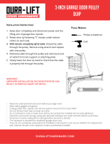
IMPORTANT INSTALLATION INSTRUCTIONS
To reduce the risk of severe injury or death to persons:
1. READ AND FOLLOW ALL INSTALLATION INSTRUCTIONS.
2. Install only on a properly balanced and lubricated garage door. An improperly balanced door
may not reverse and could result in severe injury or death. Repairs to cables, spring assemblies
and other hardware must be made by a professional service person before installing opener.
3. Disable all locks and remove all ropes connected to the garage door before installing the opener.
Ropes connected to a garage door can cause entanglement and death.
4. If possible, install door opener 7 feet or more above floor with the emergency release handle
mounted 6 feet above the floor.
5. Do not connect the opener to power source until instructed to do so.
6. Locate the Door Control within sight of the door at a minimum height of 5 feet where small
children cannot reach, and away from all moving parts of the door.
7. Install the User Safety Instruction Label on the wall adjacent to the door control and the
Maintenance Instruction Label in a prominent location on the inside of the garage door.
8. Upon completion of the installation, the door must reverse when it comes in contact with a
one-inch high object or a 2x4 laid flat on the floor.
9. Do not wear watches, rings or loose clothing while installing or servicing an opener. Jewelry or
loose clothing can be caught in the mechanism of the garage door or the opener.
11

Installation Section: Pages 12- 27
Installation Step 1
Determine Header Bracket Location
Installation procedures vary according to
garage door types. Follow the Instructions
which apply to your door.
Header
Vertical
Finished __
Ceiling
If the header bracket is not rigidly fastened to
a structural support on the header wall or
ceiling, the safety reverse system may not
work properly (see page 30). The door might
not reverse when required, and could cause
serious injury or death.
The garage door springs, cables, pulleys,
brackets and their hardware are under extreme
tension. Do not attempt to loosen, move or
adjust them yourself. Serious personal injury
or death could resulL Call for professional
garage door service.
2x4 Structural • Close the door and mark the inside
Suppo_s vertical centerline of the garage door.
• Extend the line onto the header wall
above the door.
Remember, you can fasten the header
bracket within 4 feet of the left or right
of the door center only if a torsion
spring or center bearing plate is in the
-ve_icat way; or you can attach it to the ceiling
(refer to page 14) when clearance Is
minimal. (It may be mounted on the
wall upside down if necessary, to gain
approximately 1/2".)
If you need to install the header bracket
on a 2x4 (on wall or ceiling), use lag
screws (not provided) to securely fasten
the 2x4 to structural supports as shown
here and on page 13.
• Open your door to the highest
point of travel as shown. Draw
an intersecting horizontal line
on the header wall 2" above
the high point. This height will
provide travel clearance for the
top edge of the door.
Door clearance brackets are
available for sectional doors
when headroom clearance is
less than 2". See accessory
page 38.
Ceiling
H'
Header
Wall
,,-- 2" Track
Highest Point
of Travet
Door --
Highest Point
of Travel
Proceed to Step 2, page 14.
Sectional door
with curved track
One-piece door
with horizontal track
12

Read the Safety instructions on page 12. They also apply to doors without tracks.
• Close the door and mark the
inside vertical centerline of
your garage door. Extend the
line onto the header wall
above door,
If headroom clearance is
minimal, you can install the
header bracket on the ceiling.
See page 14.
• If you need to install the
header bracket on a 2x4 (on
wall or ceiling), use lag screws
(not provided) to securely
fasten the 2x4 to structural
supports as shown.
Header Wall
Vertical
Centedine
2x4
Unfinished --
OPTIONAL CEILING MOUNT
FORHEADER BRACKET
-1
Jamb
Hardware
Header Wall
/
Highest Point
of Travel
/
One-piece door without track
jamb hardware
Header Highest Point
I_ Wall of Travel
Q
JS
One-piece door without track
pivot hardware
• Open your door to the highest point of travel as
shown. Measure the distance from the top of the
door to the floor. Subtract the actual height of the
door. Add 8" to the remainder. (See Example).
• Close the door and draw an intersecting horizontal
line on the header wall at the determined height.
If the total number of inches exceeds the height
available in your garage, use the maximum
height possible, or refer to page 14 for ceiling
installation.
EXAMPLE
Distance from top of door
(at highest point of travel) to floor........................... 92"
Actual height of door ............................................. -88"
Remainder ................................................................ 4"
Add ......................................................................... +8"
Bracket height on header wall ............................... 12"
(Measure UP from top of CLOSED door.)
Proceed to Step 2, page 14.
13

Installation Step 2 I
Install the Header Bracket
You can attach the header bracket either to the
wall above the garage door, or to the ceiling.
Follow the instructions which will work best for
your particular requirements.
Wall Header Bracket Installation
• Center the bracket on the vertical guideline with
the bottom edge of the bracket on the horizontal
line as shown (with the arrow pointing toward the
ceiling).
• Mark the vertical set of bracket holes. Drill 3/16"
pilot holes and fasten the bracket securely to a
structural support with the hardware provided.
2X4
Structural
Header Suppoff
Bracket Vedical
\ Center
Line
Highest Point of
Garage DoorTravel
Vertical
Center
Line
Spring
Waft Mount
Optional
Mounting Holes
Hardware Shown Actual Size
5/16"-9xl-5/8"
Ceiling Header Bracket Installation
• Extend the vertical guideline onto the ceiling as
shown.
• Center the bracket on the vertical mark, no more
than 6" from the wall. Make sure the arrow is
pointing toward the wall. The bracket can be
mounted flush against the ceiling when clearance
is minimal.
• Mark the side holes. Drill 3/16" pilot holes and
fasten bracket securely to a structural support with
the hardware provided,
Ceiling
Mounting Holes
Door Spring
Vertical
Center Line
14

Installation Step 3
Attach the Rail to the Header Bracket
HeaderBracket
NOTE: (Optional) With an existing Craftsman
installation, you may to-use the old header bracket
with the two plastic spacers included in the hardware
bag. Place the spacers inside the bracket on each
side of the rail, as illustrated.
• Position the opener on the garage floor below the
header bracket. Use packing material as a
protective base.
If the door spring is in the way you'll need help.
Have someone hold the opener securely on a
temporary support to allow the rail to clear the
spring.
• Position the front railend within the header bracket
and join with a 5/16"x1-1/2" clevis pin as shown.
• Insert a ring fastener to secure.
Mounting
Hole
Existing
Header Bracket
0
Clevis Pin
Spacer
Mounting
Hole
OPTION WITH
-ZXISTING CRAFTSMAN
INSTALLATION
Hardware Shown Actual Size
©
Clevis Pin 5/16"xiol/2" Ring fastener
15

Installation Step 4
Position the Opener
Follow instructions which apply to your door
type as illustrated.
A 2x4 laid flat is convenient for setting an ideal
door-to-T-rail distance.
• Raise the opener onto a stepladder as shown. You
will need help at this point if the ladder is not tall
enough.
• Open the door all the way and place a 2x4 laid flat
on the top section beneath the rail.
ff the top panel hits the trolley when you raise
the door, pull down on the trolley release arm to
disconnect the inner and outer sections. The
trolley can remain disconnected until Step 12 is
completed.
Trolley
_ Outer_Trolley InnerlTrolley ,
• ] '
Release arm
I ONE'PIECE Door without Track I
• With the door fully open and parallel to the floor,
measure the distance from the floor to the top of
the door.
• Using a stepladder as a support, raise the opener
to this height (it will be at a slight angle as shown).
• The top of the door should be level with the top of
the opener. Do not position the opener more than
2" above this point.
I
16

Installation Step 5
Hang the Opener
Two representative installations are shown. Yours
may be different. Hanging brackets should be
angled, Figure 1, to provide rigid support. On
finished ceilings, Figure 2, attach a sturdy metal
bracket to structural supports before installing the
opener. The bracket and fastening hardware are not
)rovided. See accessory page 38.
1. Measure the distance from each side ofthe
opener to the structural support.
2. Cut both pieces of the hanging bracket to
required lengths.
3. Ddll 3/16" pilot holes in the structural supports.
4. Attach one end of each bracket to a support with
5/16"-18xl -7/8" lag screws.
5. Fasten the opener to the hanging brackets with
5/16"-18x7/8" screws, lock washers and nuts.
6. Check to make sure the rail is centered over the
door (or in line with the header bracket if the
bracket is not centered above the door).
7. Remove the 2x4. Operate the door manually. If
the door hits the rail, raise the header bracket.
NOTE: Do NOT connect power to opener at this
time.
Figure I
5/
5/
Screws
Distance 5/16"-18xl-7/8"
Figure 2
Hidden .. -" ""
.. -" .-. --_ .---" -- Finished Ceiling --
Lag
Screws
_2" 5/16"-18xl -7/8" .---
" 5/16"-18x7/8" Screw
5/16" Lock Washer
--_" 5/16"-18 Nut
5/16"-18x7/8" Screw
5/16" Lock Washer
5/16 18N_
Hardware Shown Actual Size
lllll ILILIlllllll
Lag Screw
5/16'-18xl-7/8"
5/16 % 18x7/8" Nut 5/16"o18 Lock Washer 5/16"
17

Installation Step 6 I
Install the Premium Control Console
Locate the door control within sight of the door at a
minimum height of 5 feet where small children
cannot reach, and away from all moving parts of the
door and door hardware.
The door control is typically attached directly to the
wall. If installing into drywall, drill 5/32" holes and
use the anchors provided. For pre-wired installations
(as in new home construction), Console models
may be mounted to a standard single gang box
(Figure 2).
1. Strip 1/4" of insulation from one end of the bell
wire and connect it to the two screw terminals on
the back of the door control: white to 2, and
white/red to 1.
2. Pry off cover along one side with a screwdriver
blade (see Figure 1). Fasten with 6ABxl-1/4" self-
tapping screws (standard installation) or 6-32xl"
machine screws (pre-wired installation) as follows:
• Install bottom screw, allowing 1/8" to protrude
above wall surface.
• Position bottom of door control on screw head and
slide down to secure. Adjust screw for snug fit.
• Ddll and install top screw with care to avoid
cracking plastic housing. Do not overtighten.
• insert top tabs and snap on cover.
3. (For standard installation) Run the bell wire up the
wall and across the ceiling to the opener. Use
insulated staples to secure the wire in several
places. Be careful not to pierce the wire with a
staple, creating a short.
4. Connect the bell wire to the terminal screws on
the opener panel: white to 2; white/red to 1.
5. Position the antenna wire as shown.
Do not connect to live electrical wiring. Connect
only to 24 Volt low voltage wires, Connection to
live wires or higher voltage may cause serious
injury from shock, burn or electrocution.
Children operating or playing with a garage
door opener can injure themselves or others.
The garage door could close and cause
serious injury or death.
Install the door control (or any additional push
buttons) out of the reach of children and away
from all moving parts of the door and door
hardware, but where the garage door is visible.
Do not allow children to operate the push
button(s) or the remote control(s).
A moving garage door could injure someone
under iL Activate the opener only when the
door is properly adjusted, you can see it
clearly, and there are no obstructions to door
travel.
Hardware Shown Actual Size
_ ItlIl,l,lil_l,IIl,l,l,l,,_
6AB x 1-1/4" Screw Insulated
Control Console (std installation) Staples
Control Console (pre-wired) Dry Wall Anchors
Figure 1
REMOVE & REPLACE COVER
To Replace, To Remove,
Insert Twist
Top Tabs _ _ Here
First ._ J
Figure 2
PRE+WIRED
INSTALLATION
24 Volt
2-Conductor
Bell Wire
Bell Wire
BACK VIEW
Lock
PREMIUM CONTROL CONSOLE
18

6. Attach the User Safety Instruction label to the wall
near the door control, and the Maintenance
Instruction label in a prominent location on the
inside of the garage door.
Page 32 explains how to use the door control.
Do NOT connect the power and operate the
opener at this time. The trolley will travel to the
full open position but will not return to the
close position until the sensor beam is
connected and properly aligned.
See Safety Reversing Sensor instructions
beginning on page 21,
Installation Step 7
Install the Lights and the Lenses
I
Install the lights:
• Install a 75 watt maximum light bulb in each
socket. The lights will turn ON and remain lit for
approximately 4-1/2 minutes when power is
connected. Then the lights will turn OFF.
• Use standard neck Garage Door Opener bulbs for
replacement.
Install the lenses:
• Apply slight pressure on the sides of each lens
and slide the tabs into the slots in the side panels.
• For convenience, the lenses may be installed
after Adjustment Step 4 on page 30.
• Reverse the procedure to remove the lenses.
75Watt Max,
Lens Ught Bulb
_t Lens
_ _ _ Slot
Lens"
Tab
Installation Step 8
Attach the Emergency
Release Rope and Handle
• Thread one end of the rope through the hole in
the top of the red handle so "NOTICE" reads right
side up as shown. Secure with an overhand knot,
at least 1" from the end of the rope to prevent
slipping.
• Thread the other end of the rope through the hole
in the release arm of the outer trolley.
• Adjust rope length so the handle is 6 feet above
the floor. Secure with an overhand knot.
If it is necessary to cut the rope, heat seal the
cut end with a match or lighter to prevent
unraveling.
Do not use the red handle to pull the door
open or closed. The rope knot could become
untied and you could fall. Use the emergency
release only to disengage the trolley and, if
possible, only when the door is closed.
Garage doors are heavy. If the door is open
when the handle is pulled, the door could
close inadvertently if it is not properly
balanced. Serious injury may result to persons
under the door. Make sure the doorway is clear
of persons and obstructions before pulling
handle when door is open.
Release arm
Release Handle
19

Installation Step 9
Electrical Requirements
I
To reduce the risk of electric shock, your garage
door opener has a grounding type plug with a third
grounding pin. This plug will onlyfit into a grounding
type outlet.
Ifthe plug doesn't fit intothe outlet you have,
contact a qualified electrician to install the proper
outlet.
I
To avoid installation difficulties, I
do not run the opener at this time.
I
To prevent electrocution or fire, Installation
and wiring must be in compliance with local
electrical and building codes.
Do NOTuse an extension cord, 2-wire adapter,
or change the plug in any way to make it fit
your outlet.
QQ
Right Wrong
If permanent wiring is required by your local code, refer to the following procedure:
To make a permanent connection through the
7/8" diameter hole in the top of the opener
(according to local code):
• Remove the opener cover screws and set the
cover aside,
• Remove the attached 3-prong cord.
• Connect the black (line) wire to the screw on the
brass terminal; the white (neutral) wire to the
screw on the silver terminal; and the ground wire
to the green ground screw. The opener must be
grounded.
• Reinstall the cover.
I To avoid installation difficulties,do not run the opener at this time,
Ground Tab
Green
Scr6w
Wire
White Wire
Permanent
Wiring
Connections
Black
Wire
Wire
2O
/