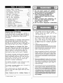
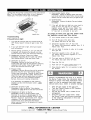
Kenmore 14117678801 Owner's manual
- Category
- Barbecues & grills
- Type
- Owner's manual
This manual is also suitable for

Use and Care Guide
! T
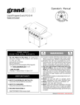
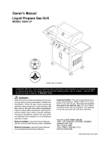
Liquid Propane Gas (LPG) Grill
Model141.16678801
Natural Gas (NG)Grill
Model141.17678801
®
• Safety
• Assembly
• Use and Care
• Cooking Guide
• Frequently Asked Questions
Call us first if you have any problem with
this product. We can help you with ques-
tions about assembly and grill operation or
if there are damaged or missing parts
when you unpack this unit from the ship-
ping box. Please call before contacting
your local retailer.
1- 888-317-7642
8am-8pm CST, Monday throu,qh Friday
• NOTE TO ASSEMBLER/INSTALLER:
Leave this guide with the consumer.
• NOTETO CONSUMER:
Keep this guide for future reference.
• RECORDYOURSERIAL#
(see silver CSA label on main body of grill)
• Failure to comply with these instructions could
result in a fire or explosion that could cause
serious bodily injury, death or property damage.
• Whether this grill was assembled by you or
someone else, you must read this entire manual
before using your grill to ensure the grill is
properly assembled, installed and maintained.
• Use your grill at least 3 feet away from any
wall or surface. Use your grill at least 3 feet
away from combustible objects that can melt or
catch fire such as vinyl or wood siding, fences
and overhangs or sources of ignition including
pilot lights on water heaters and live electrical
appliances.
• THIS GAS APPLIANCE ISDESIGNED FOR OUT-
DOOR USE ONLY.
• Never use your gas grill in a garage, porch,
shed, breezeway or any other enclosed area.
• Never obstruct the flow of ventilation air
around your gas grill housing.
• Never disconnect the gas regulator or any gas
fitting while your grill is lit. A lit grill can ignite
leaking gas and cause a fire or explosion which
could result in property damage, personal injury
or death.
Guide # P80106008H - Date:2008/01/15
Sears, Roebuck and Co., Hoffman Estates, IL 60179, USA www.sears.com

Primary Safety Warnings ........................... 1-3
Warranty Terms and Conditions .................. 2
Pre-Assembly Instructions .............................. 3
Part Diagrams and Lists .......................... 4-9
Assembly Instructions .............................. 10-12
LP Gas Tank Installation ...................... 13-15
Natural Gas Connection .............................. 16
Use & Care Instructions:
• Lighting Instructions ................................. 17
• Troubleshooting ......................................... 18
• Rotisserie Instruction ......................... 19--21
• Cleaning and Maintenance ................ 22-23
• Cooking Guide ................................... A1-A6
• Frequently Asked Questions ............ AS-A9
• Repair Protection Agreement ............... A10
Kenmore Elite Full Warranty
1. Do not store spare LP cylinder
within 10 feet (3m) of this appliance.
2. Do not store or use gasoline or
other flammable liquids and
vapors within 25 feet (8m) of this
appliance.
3. When cooking with oil/grease, do
not allow the oil/grease to get
hotter 350°F (177°C)
4. Do not leave oil/grease unattended.
If this grill fails due to a defect in material or
workmanship within two years fro(_, the date of
purchase, call 1-800-4-MY-HOME to arrange for
free repair (or replacement if repair proves
impossible).
Limited Warranty on Stainless Steel Burners
Any stainless steel burner that ever rusts
through will be replaced free of charge. After
the second year from the date of purchase you
must pay the labor cost to have it installed.
Limited Warranty on Selected Grill Parts
For three years from the date of purchase, any
stainless or painted steel part will be replaced
Free of charge if it rusts through. After the
second year from the date of purchase you
*nust pay the labor cost to have it installed.
All warranty coverage excludes ignitor batteries
and grill part paint loss or rusting, which are
either expendable parts that can wear out from
normal use in less than a year, or are condi-
tions that can be the result of normal use,
accident or improper maintenance.
All warranty coverage is void if this grill is ever
used for commercial or rental purposes.
All warranty coverage applies only if this grill is
Jsed in the United States.
This warranty gives you specific legal rights,
and you may have other rights which vary from
state to state.
Sears, Roebuck and Co., Hoffman Estates, IL
i
i
© Sears Brands, LLC
• LPG models must be used with Liquid
Propane Gas and the regulator assembly
supplied. Natural Gas models must be used
with Natural Gas only.
Keep gas regulator hose away from hot grill
surfaces and dripping grease. Avoid unneces-
sary twisting of hose. Visually inspect hose
prior to each use for cuts, cracks, excessive
wear or other damage. If the hose appears
damaged do not use the gas grill. Call Sears
at 1-888-317-7642 for a certified replacement
hose.
California Proposition 65
Combustion byproducts produced when using
this product contain chemicals known to the
State of California to cause cancer, birth de-
fects, or other reproductive harm.
Brass components on the grill, such as hose
fittings, propane cylinder valves (sold sepa-
rately) and burner valve stems, contain lead
which is known to the State of California to
cause cancer, birth defects, or other reproduc-
tiveharm.
Never use charcoal or lighter fluid in this gas
grill. Failure to comply with these instructions
could result in a grease fire or explosion that
could cause serious bodily injury, death or
propertydamage.
The Grease Draining Tray and Grease Recep-
tacle must be visually inspected before each
grill use.Remove any grease and wash Grease
Draining Tray and Grease Receptacle with a
mild soap and warm water solution. Failureto
comply with these instructions could re-
sult in a grease fire or explosion that cou Id
cause serious bodilyinjury, death or prop-
erty damage.

Failure to comply with these instructions may
result in a hazardous situation which, if not
avoided, may result in injury.
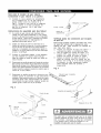
Spiders and small insects can spin webs and
nest in the grill BL transit and
warehousing as flow
obstruction around the
Burner FIRE"
can caus ate an
unsafe
:K
as folb o this
at least _ll or
whenever and if
your grill ha
period of time
1. Remove the the rear of each Main
Burner using a Phillips Head Screwdriver.
2. Carefully lift each Burner up and away from the
Gas Valve Orifice.
3. Check and clean Burner/Venturi Tubes for
insects and insect nests. A clogged tube can
lead to a fire beneath the grill.
4. Refer to the figure below and perform one of
these 3 cleaning methods:
[] METHOD 1: Bend a stiff wire or wire coat
hanger into a small hook as shown and run
the hook through the Burner Tube and inside
the Burner several times to remove debris.
TO CLEAN BURNERTUBE,
INSERT HOOK Burner Port
HERE L_ Foo_
_Burner Tube
[] METHOD 2: Use a bottle brush with a flexible
handle and run the brush through the Burner
Tube and inside the Burner several times to
remove any debris.
[] METHOD 3: Use an air hose to force air
through each Burner Tube. The forced air
should pass debris or obstructions through
the Burner and out the Ports.
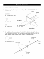
For safe operation ensure the Gas Valve Assem-
bly Orifice is inside the Burner Tube before using
your grill. See figure. If the Orifice is not inside
the Burner Tube, lighting the Burner may cause
explosion and/or fire resulting in serious bodily
injury and/or property damage.
Gas VaIve AssembIy Orifice
\
\
BurnerTube
To expedite the assembly process follow these
general guidelines:
[] Tools Required forAssembly :
• protective work gloves
• Phillips Head Screwdriver
[]
[]
[]
While it is possible for one person to unpack this gas
grill, obtain assistance from another person when
handling the large pieces.
Use the Hardware and Part Diagrams to ensure all
items are included and free of damage.
Do not assemble or operate the grill if it appears
damaged. If there are damaged or missing parts
when you unpack the shipping box or you have
questions during the assembly process, call the:
Grill Information Center 1-888-317-7642
8am-8pm CST, Monday throu.qh Friday
Grill Installation Codes
The installation must conform with local codes or, in the
absence of local codes, with the National Fuel Gas
Code, ANSI Z223.1/NFPA 54, Storage and Handling of
Liquefied Petroleum Gases, ANSI/NFPA58,Natural Gas
and Propane Installation Code, CSA B149.1, Propane
Storage and Handling Code, B149.2.
When using electrical appliances, basic
safety precautions should always be used.
If you smell gas:
1. Shut off gas to the appliance.
2 Extinguish any open flame.
3. Open lid.
4. If odor continues, keep away from
the appliance and immediately call
your gas supplier or your fire
department.
• This appliance, when installed, must be electri-
cally grounded in accordance with local codes
or, in the absence of local codes, with the
National Electrical Code, ANSI/NFPA 70, or the
Canadian Electrical Code, CSA C22.1.
• Keep any electrical supply cord and the fuel
supply hose away from any heated surfaces.

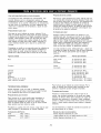
PART#
P06001062A
S112G0408E
S313G04081
S112G0408E
$313G04081
S112G0306E
Alreadylnstalled onthe
PARTDESCRIPTION
Hardware Pack
Phillips Head Screw 1/4"xl/2"
Flange Nut 1/4"
Phillips Head Screw 1/4"xl/2"
Flange Nut 1/4"
Phillips Head Screw 3/16"x3/8"
QTY PURPOSEOFPART
1 For use in assemblyofMode1141.16678801 & 141.17678801
7
Attaches Side Shelf Left to Bowl Side Panel
2
7
Attaches Side Burner Frame toBowl Side Panel
2
2 Attaches Decorative Panel to Bowl Side Panel
Cart Rear and Right Cart Side Panel
P055360014 Hose Holder(LPG Only)
2 Attaches Regulator with Hose to Cart Rear Panel and Right
Cart Side Panel
P055360014 Hose Holder (NG Only) 1 Attaches Extension Hose to Right Cart Side Panel
Already installed on the Cart Bottom Shelf
S233G05461 Wing Bolt5/16"x4-1/2"
S303G0504D Special Nut 5/16"
Already installed on the Tool Holder
$313G04081 Flange Nut 1/4"
1
Secures Gas Tank
1
I 2 IAttaches Tool Holder to Left Side Shelf
©
Phillips Head Screw Flange Nut 1/4"
1/4" x 1/2" Qty. 4
Qty. 14 Part # S313G04081
Part # S112G0408E
r-
Already installed on the Cart Bottom Shelf
_!/_!/!/!/!/!/_!/!/!/!1
Wing Bolt 5/16"x4-1/2"
Qty. 1
Part # $233G05461
Scale 1:2
Speciai Nut 5/16"
Qty. 1
Part # S303G0504D
Scale 1:2
Already installed on the Tool
Holder
Already installed on the Cart Rear
and Right Side Panel
Hose Holder
Qty. 2 (Model 141.16678801)
Qty. 1 (Model 141.1767880!)
Part # P055360014
Scale 1:2
Phillips Head Screw 3/16"x3/8"
Qty. 2
Part # S112G0306E
Flange Nut 1/4"
Qty. 2
Part # $3!3G04081
* Two Battery/AA included in the Hardware Pack.
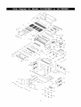
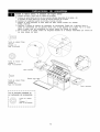
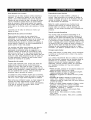
4

10
11
79
78
\
75
76
24
20_
B8
13
14
23_
33 28
69
8 18
9 15
12 19
\ B2
% B9
B10
A4_
B3

KEY DESCRIPTION PART # QTY
1 Lid Assembly P0014707M4 1
2 Temperature Gauge P00601287C 1
2A Temperature Gauge Seat P00614027C 1
3 Lid Handle P00205068M 1
3A Lid Handle Heat Insulating Spacer P06801028A 2
4 Protective Pad P055180021 4
5 Name Plate P00410039C 1
6 Cooking Rack/Secondary P01518004A 1
7 Cooking Grid 13" P01604013B 2
8 Cooking Grid 6.5" P01604010A 1
9 Cooking Grid/Infrared Burner P01615030F 1
10 Heat Diffuser P017080364 5
11 Burner/Main P020080324 5
12 Grill Bowl P0071344E4 1
13 Grease Draining Plate P069020174 2
14 Heat Diffuser Bracket, Front P033280154 5
15 Heat Diffuser Bracket, Rear P033280174 5
16 Burner Heat Shield P069060344 1
17 Grease Tray Heat Shield, Upper P069030634 1
18 Wind Shield, Rear P069040444 1
19 Burner Bracket P0220509G4 1
Gas Valve/Manifold Assembly (LPG Only) Y0060410 1
20
Gas Valve/Manifold Assembly (NG Only) Y0060411 1
21 Gas Manifold P03708002C 1
22 Gas Manifold Connector P03715006D 1
23 Gas Collector Box with Electrode P02609009M 5
24 Electric Wire Set P02615123A 1
25 Electric Wire Set, 7-contact P02615124A 1
26 Control Panel, Upper P0291182FS 1
27 Control Panel P0291183ES 1
27A Control Panel Bracket P03303029D 2
28 Electric Ignitor, 4-port P02502274C 2
30 Electric Ignitor Protector, 5-Port P03343007A 2
31 Bowl Wind Shield P069060764 1
32 Control Knob P03428073H 6
32A Control Knob Spring P05504021A 8
33 Control Knob Seat P03413011J 7
Grease Tray (LPG Only) P02717234A 1
34
Grease Tray (NG Only) P02717244A 1
34A Grease Tray Heat Shield (LPG Only) P06901017C 1
35 Grease Tray Handle P0272003H4 1
36 Wheel for Grease Tray P05354002A 4
37 Regulator With Hose, 27" (LPG Only) P03601039A 1
38 Regulator (NG Only) P03628001B 1
39 Hose Holder P055360014 2
40 Hose, 12ft., 1/2" ID (NG) P03704001A 1
41 Extension Hose (NG Only) P03718002L 1
42 Infrared Burner Assembly P020050104 1
43 Thermocouple Bracket P033270354 1
44 Infrared Burner Electrode P02618007M 1
45 Infrared Burner Thermocouple P05305018A 1

KEY DESCRIPTION PART# QTY
46 BowlSupportBracket,Left P01301010K 1
47 BowlSupportBracket,Right P01302010K 1
CartBottomShelf(LPGOnly) P010200024 1
48
CartBottomShelf(NGOnly) P010200034 1
49 CartSidePanel,Left P076140104 1
50 CartSidePanel,Right P076150214 1
51 CartPartitionPanel,Left P07512008N 1
52 CartPartitionPanel,Right(NGOnly) P07512009N 1
53 CartBottomPanelBracket P033280244 4
54 CartRearPanel P077010704 1
55 Caster2-1/2in. P05117010A 2
56 Caster2-1/2in.,with Brake P05110007A 2
57 CartSeat,LF P05327009Q 1
58 CartSeat,RF P05327011Q 1
59 CartSeat,LR P05327010Q 1
60 CartSeat,RR P05327012Q 1
61 Door,Left P04302040L 1
62 Door,Right P04303040L 1
63 DoorHandle P00205073M 2
64 DoorHingeBracket,UpperLeft P033140414 1
65 DoorHingeBracket,UpperRight P033140494 1
66 CartBracket P033060284 1
67 Weight P05344004Q 1
68 Handle/Drawer P00212003M 2
69 Drawer Y0420010 2
70 CartPartitionPanelBracket,FrontLeft P019070101 1
71 CartPartitionPanelBracket,FrontRight P019070091 1
72 CartPartitionPanelBracket,Rear P019070111 2
73 DoorMagnet P05523005M 4
74 DrawerSlideSet P01907006B 2
75 SideShelf,Left P01106009S 1
76 DecorativePanelforSideShelf P07503007P 1
77 LightingStick P05313012E 1
78 ToolHolder P05209004H 1
79 ToolHooks P055141314 4
A1 SideBurnerFrame P01108013S 1
A2 DecorativePanelforSideBurnerFrame P07502017P 1
A3 SideBurnerBody P023010194 1
A4 SideBurnerLid P01127007S 1
SideBurnerwithBrassRing(LPOnly) P02002007A 1
A5
SideBurnerwithBrassRing(NGOnly) P02002014A 1
A6 SideBurnerPotSupport P008050104 1
A7 SideBurnerElectrode P02614053C 1
SideBurnerGasValve(LPGOnly) Y0060589 1
A8
SideBurnerGasValve(NGOnly) Y0060590 1
A9 SideBurnerControlKnob P03401013H 1
A10 SideBurnerControlKnobSeat P03408053J 1
A11 SideBurnerConnectionHose,Plug P037050511 1

KEY DESCRIPTION PART# QTY
A12 SideBurnerConnectionHose,Bracket P033410014 2
A13 SideBurnerBracket P033270374 1
A14 ElectricWire,1-contact P02627001L 1
B1 RotisserieBurnerAssembly P02007067A 1
RotisserieBurnerOrifice(LPGOnly) P06527003A 1
B2
RotisserieBurnerOrifice(NGOnly) P06527004A 1
B3 RotisserieBurnerExtensionTube P03717044B 1
B4 RotisserieBurnerElectrodeAssembly P02610005B 1
B5 RotisserieBurnerWindShield P069060724 1
B6 RotisserieBurnerFrame P020070154 1
B7 RotisserieBurnerWindShield,Front P069050504 1
B8 ControlKnobForRotisserieBurner P03411423J 1
B9 RotisserieBurnerThermocouple P05305021A 1
B10 RotisserieBurnerThermocoupleBracket P033280474 1
RotisserieAssembly Y0250142 1
HardwarePack P06001062A 1
UseandCareGuide P80106008H 1
For the repair or replacement parts you need:
Call anytime 1-800-4-MY-HOME® (1-800-469-4663)
To obtain the correct replacement parts for your gas grill, please refer to the part numbers in this parts
list. The following information is required to ensure you receive the correct parts:
1. Model and Serial Number (see CSA label on grill)
2. Part Number
3. Part Description
4. Quantity of parts needed
Important: Use only Sears replacement parts. The use of any part that is not a Sears replacement part
can be dangerous and will also void your product warranty. Keep this Use and Care Guide for
convenient referral and for part replacement.

7
6
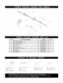
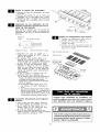
KEY PARTS DESCRIPTION PART # QTY
1 Rot. Motor Bracket P03307003G 1
2 Rot. Screw #10-24x3/4" UNC $112G10124 2
3 Rot. Hex Nut #10-24 $362G10124 2
4 Rot. Washer 3/16" S411G0308B 2
5 Rot. Spit P05508170F 1
6 Rot. Holding Fork P05508169F 2
7 Rot. Thumbscrew 3/8"xl/2" S196G0608B 3
8 Rot. Collar P05508168F 1
9 Rot. Bushing P055081 67F 1
10 Rot. Motor/AC P07101025A 1
[)IIIIIIIIIIIIIIII
Rot. Thumbscrew Rot. Screw#10-24x3/4" Rot. Washer 3/16" Rot. Hex Nut#10-24
3/8"x1/2" UNC Qty. 2 Qty. 2
Qty. 3 Qty. 2 Part# S411G0308B Part# S362G10124
Part# S196G0608B Part# $1!2G10124

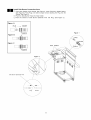
Install Left Side Shelf and Right Side Burner Frame
[] Raise lid and remove all packing materials.
[] Place the Side Shelf over the Left Side Shelf Brackets and Side Burner Frame over the
Right Side Shelf Brackets.
[] Tighten securely by using Screws and Nuts provided.
[] Secure Decorative Panel to Bowl Side Panel using Phillips Head Screw 3/16"x3/8".
[] Remove 2 Flange Nuts from the Tool Holder. Slide the 4 Tool Hooks onto the Tool
Holder with the hooks facing the Left Side Shelf. Attach Tool Holder to Side Shelf
using these Flange Nuts.
[] From the front of the grill, slide the assembled Tray side tabs over the side rails
underneath the Grill Bowl.
Phillips Head Screw
1/4" x 1/2"
Qty. 14
Part# S112G0408E
Phillips Head Screw
3/16"x3/8"
Qty. 2
Part # S112G0306E
Decorative Panel
Flange Nut 1/4"
Qty. 4
Part# $313G04081
Grease Tray
\
Decorative Panel
I-
Already installed on the Tool
Holder
Flange Nut 1/4"
Qty. 2
Part# $313G04081
10

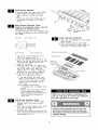
Install Side Burner Connection Hose
[] Push back Sleeve of the Socket. See Figure A. Insert Plug then release Sleeve.
See Figure B. Push Plug until sleeve snaps forward locking the Plug into the
Socket. See Figure C.
[] Push the Side Burner Hose into hose holder.
[] Push the Socket of Side Burner Electrode Wire into Plug. (See Figure 2).
Figure A
PLUG SOCKET
Figure B
Figure C
_SLEEVE
Hose Holders
Figure 1
Plug
Figure 2
Side Burner Electrode Wire
Plug Socket
11

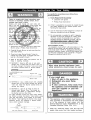
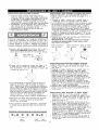
Install Ignitor Batteries
[] Unscrew Ignitor Cap from Control Panel.
[] Place supplied AA batteries into the
ignitor Slots with positive pole facing
you.
[] Position the Caps and Springs over the
AA batteries and tighten onto Control
Panel.
Main Burners Electrode Check
Perform this Electrode Check with the
assistance of another person.
This test will ensure that the Spark Electrode Tips
are properly positioned so your grill lights easily
and properly.
f
H nstall Cooking Components
[] Place the Heat Diffusers on lower ledge
above Burners.
[] Place Cooking Grids on bowl ledge.
[] Place the Secondary Cooking Rack into
the slots on Grill Bowl Side Panels
Spark Receiver Spark Electrode Tip
[]
[]
[]
[]
Be sure all Control Knobs are set to
"OFF" and open the Grill Lid.
Have your assistant stand behind to the
right of the grill and look toward the front
of the grill bowl. Never put your face
inside the Grill Bowl.
Press the Ignitor Cap. You should hear
a "clicking" sound. Your assistant should
see a blue spark within each Gas
Collector Box. If a spark is present the
Electrode Tips are properly positioned.
If no spark is seen, the Spark Gap
needs to be adjusted as follows:
• If the gap between the Spark Elec-
trode Tip and Receiver is more than
3/16" use long nose pliers to gently
squeeze the Gas Collector Box to
narrow gap.
• If no "clicking" sound is heard:
• AA Batteries may be installed back-
wards.
• Electric wires may be loose. Remove
the AA Batteries and inspect the
Ignitor Junction Box found behind the
Control Panel and reconnect any
loose wires.
H Side Burner Electrode Check
[] Open side burner lid. Remove plastic
shipping band from burner and pot
support.
[] Push and turn side burner Control Knob
to _€. Look for spark between tip of
electrode and burner.
[] If you don't see a spark from side burner elec-
trode, adjust gap between electrode and
burner surface to 3/16 in.
Secondary Cooking
Cookin
SIots for
Secondary
Cooking Rack
Diffusers
When you have finished assembling your
grill be sure that all screws are tightened
for safe operation of your grill.
Failure to read and follow the Use and Care
Instructions could result in a fire or explosion
that could cause serious bodily injury, death or
property damage.
12

CORRECT LP GAS TANK USE
[] LP Gas grill models are designed for use with a
standard 20 lb. Liquid Propane Gas (LP Gas) tank,
not included with grill. Never connect your gas grill to
an LP Gas tank that exceeds this capacity. A tank of
approximately 12 inches in diameter by 18-1/2 inches
high is the maximum size LP Gas tank to use. You
must use an "OPD" gas tank which offers a listed
Overfill Prevention Device. This safety feature
prevents tank from being overfilled which can cause
malfunction of LP Gas tank, regulator and/or grill.
[] The LP Gas tank must be constructed and marked in
accordance with the Specifications for LP-Gas Cylin-
ders of the U.S. Department of Transportation (D.O.T.)
or the National Standard of Canada, CAN/CSA-B339,
Cylinders, Spheres and Tubes for Transportation of
Dangerous Goods; and Commission, as applicable.
[] The LP Gas tank must have a shutoff valve, terminat-
ing in an LP Gas supply tank valve outlet, that is
compatible with a Type 1 tank connection device. The
LP Gas tank must also have a safety relief device
that has a direct connection with the vapor space of
the tank.
[] The tank supply system must be arranged for vapor
withdrawal.
[] The LP Gas tank used must have a collar
to protect the tank valve.
[] Never connect an unregulated LP gas tank to your
gas grill. The gas regulator assembly supplied with
your gas grill is adjusted to have an outlet pressure
of 11" water column (W.C.) for connection to an LP
gas tank. Only use the regulator and hose assembly
supplied with your gas grill. Replacement regulators
and hose assemblies must be those specified by
Sears. See Parts List.
[] Have your LP Gas dealer check the release valve
after every filling to ensure it remains free of defects.
[] Always keep LP Gas tank in upright position.
[] Do not subject the LP Gas tank to excessive heat.
[] Never store an LP Gas tank indoors. If you store
your gas grill in the garage always disconnect the
LP Gas tank first and store it safely outside.
[] LP Gas tanks must be stored outdoors in a well-
ventilated area and out of the reach of children.
[] Disconnected LP Gas tanks must not be stored in a
building, garage or any other enclosed area.
[] The regulator and hose assembly can be seen after
opening the doors (if applicable) and must be
inspected before each use of the grill. If there is
excessive abrasion or wear or if the hose is cut, it
must be replaced prior to using the grill again.
[] Never light your gas grill with the lid closed or
before checking to ensure the burner tubes are fully
seated over the gas valve orifices.
[] Never allow children to operate your grill. Do not
allow children or pets to play near your grill.
13
[] Use of alcohol, prescription or non-prescription
drugs can impair your ability to properly assemble
and safely operate your grill.
[] Keep fire extinguisher readily accessible. In the
event of a oil/grease fire, do not attempt to
extinguish with water. Use type B extinguisher
or smother with dirt, sand or baking soda.
[] In the event of rain, cover the grill and turn off
the burner and gas supply.
[] Use your grill on a level, stable surface in an
area clear of combustible materials.
[] Do not leave grill unattended when in use.
[] Do not move the appliance when in use.
[] Allow the grill to cool before moving or storing.
[] Do not use your grill as a heater.
[] This grill is not intended to be installed in or on
recreational vehicles and/or boats.
[] Never use charcoal in this gas grill.
A Do not store a spare LP-Gas tank under or near
this appliance.
B. Never fill the tank beyond 80 percent full; and
C. If the information in "(a)" and "(b)" is not followed
exactly, a fire causing death or serious injury may
occur.
• Use your grill at least 3 feet away from any
wall or surface. Use your grill at least 3 feet
away from combustible objects that can melt
or catch fire such as vinyl or wood siding,
fences and overhangs or sources of ignition
including pilot lights on water heaters and live
electrical appliances.
• Outdoor cooking gas appliance shall not be
used under overhead combustible construction.
• Never use your gas grill in a garage, porch, shed,
breezeway or any other enclosed area.
• Never obstruct the flow of ventilation air around
your gas grill housing.
• In windy conditions, always position the front of
grill to face oncoming wind to reduce smoke and
heat blowing in your face and prevent potential
hazards to self and grill.
NOTE: For illustration purpose,
your grill model may differ

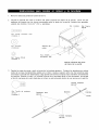
NOTE about LP Gas Tank Exchange Programs
• Many retailers that sell grills offer you the option of
replacing your empty LP Gas tank through an exchange
service. Use only those reputable exchange compa-
nies that inspect, precision fill, test and certify their
tanks. Exchange your tank only for an OPD safety
feature-equipped tank as described in the LP Gas tank
section of this guide.
• Always keep new and exchanged LP Gas tanks in an
upright position during use, transit or storage.
• Leak test new and exchanged LP Gas tanks BEFORE
connecting one to your grill.
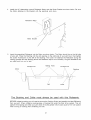
How to Leak Test your LP Gas Tank
For your safety:
• All leak tests must be repeated each time your LP Gas
tank is exchanged or refilled.
• When checking for gas leaks do not smoke.
• Do not use an open flame to check for gas leaks.
• Your grill must be leak tested outdoors in a well-
ventilated area, away from ignition sources such as
gas fired or electrical appliances. During the leak test,
keep your grill away from open flames or sparks.
• Do not use household cleaning agents. Damage to
gas assembly components can result.
[] Use a clean paintbrush and a 50/50 mild soap and
water solution.
[] Brush soapy solution onto LP Gas tank in the areas
indicated by the arrows. See diagram.
[] If growing bubbles appear do not use or move the
LP Gas tank. Call an LP Gas Supplier or your Fire
Department.
J
4
/
To Install LP Gas Tank (LPG model only):
Secure a 201b LP Gas Tank to Gas Grill
[] Screw the Wing Bolt and Special Nut to Cart
Bottom Shelf.
[] Turn your LP Gas Tank Valve clockwise to the
closed or OFF positon.
[] Place LP Gas tank into tank hole on bottom shelf
or (on select models) slide the Tank Tray out of
the cabinet until it is fully extended. The Tank Tray
has an auto lock position and may need to be
pulled firmly.
[] install the tank so the Tank Valve faces the front
right corner of cabinet.
[] Secure Gas Tank with Special Nut and Wing Bolt.
The Special Nut has
to be mounted to the
Wing Bolt BEFORE
inserting tank into
tank hole.
With the Special Nut,
the Wing Bolt holds
the tank foot firmly.
H!I!I/I!/!/!I!/!/!I//!///////_
If growing bubbles appear do not use or move
the LP Gas tank. Contact an LP Gas Supplier
or your fire department!
Special Nut 5/16" Wing Bolt 5/16"x4-1/2"
Qty 1 Qty. 1
Part # S303G0504D Part # $233G05461
Scale 1:2 Scale 1:2
NOTE: Many different size propane gas tank bottom
collars are available in the market, especially with the
popularity of tank exchange programs, tf your tank
bottom collar does notfit into the tank hole after attaching
the special nut tothe wing bolt, simply remove the special
nut and secure the tank using the wing bolt only.
14

LP Gas Model only:
Connect Regulator with Hose to your LP Gas Tank
[] Turn all Burner Valves to the OFF position.
[] Inspect the valve connection port and regulator
assembly for damage or debris. Remove any
debris. Never use damaged or plugged equip-
ment.
[] Connect the regulator assembly to the tank valve
and HAND TIGHTEN nut clockwise to a full stop.
DO NOT use a wrench to tighten because it could
damage the Quick Coupling Nut and result in a
hazardous condition.
[] Open the tank valve 1/4 to 1/2 (counterclockwise)
and use a soapy water solution to check all
connections for leaks before attempting to light
your grill. See "Checking for LP Gas Leaks". If
a leak is found, turn the tank valve off and do not
use your grill until the leak is repaired.
Type 1 connection per
ANSI Z21.58-2007/CSA
1.6-2007 Quick
Couphng Nut
CAUTION: When the appliance is not in use the gas
must be turned off at the tank. Place dust cap on
cylinder valve outlet whenever the cylinder is not in
use. Only install the type of dust cap on the cylinder
valve outlet that is provided with the cylinder valve.
Other types of caps or plugs may result in leakage
of propane.
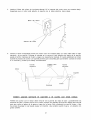
Check all connections for LP Gas Leaks
Never test for leaks with a flame. Prior to first use,
at the beginning of each season, or every time
your LP Gas tank is changed, you must check for
gas leaks. Follow these three steps:
[] Make a soap solution by mixing one part liquid
detergent and one part water.
[] Turn the grill Control Knobs to the full OFF
position, then turn the gas ON at source.
[] Apply the soap solution to all gas connections
indicated by the arrows. See diagram. If
bubbles appear in the soap solution the
connections are not properly sealed. Check
each fitting and tighten or repair as necessary.
Gas Valve / Manifold Assembly
LP Gas Tank
If you have a gas leak that cannot be repaired ]
by tightening, turn off the gas at the source,
disconnect fuel line from your grill and call /
1-800-4-MY-HOME ® or your gas supplier for repair_
assistance, j
Disconnecting A Liquid Propane Gas (LPG)
Tank From Your Grill
[] Make sure the Burner Valves and LP Gas tank
valve are off. (Turn clockwise to close.)
[] Detach the hose and regulator assembly from
the LP Gas tank valve by turning the Quick
Coupling Nut counterclockwise.
15

Natural Gas Model only:
Connecting Natural Gas To Your Grill
[] Connect the Swivel nut of the 12' Natural Gas
Hose to the vertical fitting of NG Regulator as
shown in Fig. 1. Connect the other hose end
(male plug) to the gas supply line from house.
Also, read and follow all natural gas safety
instructions below.
Natural Gas Safety Instructions
[]
[]
[]
[]
[]
Your natural gas grill is designed to operate on
natural gas only, at a pressure of 4" water column
(W.C.) with natural gas regulator. The gas pres-
sure Regulator supplied with this appliance must
be used. This Regulator is set for an outlet
pressure of 4" W.C.
Install a Shutoff Valve at the gas supply source
outdoors at a point after the gas pipe exits the
outside wall and before the quick-disconnect
hose. Or install it at the point before the gas line
piping enters the ground. See Fig. 2.
Pipe sealing compound or pipe thread tape
resistant to the action of natural gas must be used
on all male pipe thread connections.
Disconnect your gas grill from fuel source when
the gas supply is being tested at high pressures.
This gas grill and its individual shutoff valve must
be disconnected from the gas supply pipe system
during any pressure testing of that system at
pressure in excess of 1/2 psi (3.5kpa).
Turn off your gas grill when the gas supply is
being tested at low pressures. The grill must be
isolated from the gas supply pipe system by
closing its individual manual shutoff valve during
any pressure testing of the gas supply pipe
system at pressures equal to or less than 1/2 psi
(3.5kpa).
Fig. 1
• ,_se, 12 ft./NG
Vertical fitting_
Swivel nut
Check all connections for NG Leaks
Never test for leaks with a flame. Prior to first use,
at the beginning of each season, you must check
for gas leaks. Follow these three steps:
[] Make a soap solution by mixing one part liquid
detergent and one part water.
[] Turn the grill Control Knobs to the full OFF
position, then turn the gas ON at source.
[] Apply the soap solution to all gas connections
indicated by the arrows. See Fig. 3. If bubbles
appear in the soap solution the connections are
not properly sealed. Check each fitting and
tighten or repair as necessary.
Fig. 3
Gas Valve Manifold Assembly
/
Fig. 2
NG Regulator
Outside Wall
To Grill
Male Fitting
Inside Wall
Gas ;upply
Shut Off
Locking
Shut Off
Quick
Disconnect
16
Hose, 12 ft./NG
If you have a gas leak that cannot be repaired
by tightening, turn off the gas at the source,
disconnect fuel line from your grill and call
1-800-4-MY-HOME ° or your gas supplier for repair
assistance.

Grill Lighting Instructions
1. Before each use, check all hoses for cracks, nicks, cuts,
burns or abrasions. If a hose is damaged in any way, do
not use your grill before replacing the hose with an
authorized part from the Parts List. Also make sure all
gas supply connections are securely tightened.
2. Familiarize yourself with the safety and Use and Care
instructions in this Manual. Do not smoke while lighting
grill or checking gas supply connections.
3. Be sure the LP Gas tank is filled.
4. Open the Grill Lid during lighting.
Failure to replace a faulty hose, secure gas supply
connections or to open the Lid before proceeding
to the Lighting Procedures could result in a fire
or explosion that could cause serious bodily injury,
death, or property damage.
5. Set Control Knobs to OFF and open the LP Gas
tank valve SLOWLY 1/4 of a turn. For Natural Gas
open the Shut Off Valve at source.
|
Open LP Gas tank
OFF
6. Push and turn Burner Control Knob to _€ and you will
hear a clicking sound as the burner is being ignited.
Once the burner is lit, turn the knob back to Hi.
I
Low_
OFF
7. Ifignition does not occur in 5 seconds, turn gas off at
source and turn Control Knobs OFF. Wait at least 5
minutes for gas to clear, then retry. If your grill still fails
to light turn the burner Control Knob(s) and gas source
OFF and conduct a leak test of ALL gas connections
and gas sources as explained in the LP Gas Tank
installation of this manual. If no leaks are detected,
wait 5 minutes for any gas to clear and repeat the
lighting procedure.
8. After one Burner is lit, turn the tank valve SLOWLY one
more 1/4 of a turn.
9. Turn Knob for each other burner and light as you move
toward the fuel source.
Burner Control Knobs on Control Panel
Main Burner Rotisserie Infrared
Burner Burner
17
Rotisserie Burner Lighting Instructions
1. Follow steps 1 through 5 of the Grill Lighting
Instructions.
2. Push and turn Burner Control Knob to _ and hold
knob in.
3. Keep pressing while you turn knob to Hi and hold in
5 - 10 seconds before releasing.
4. If ignition does not occur in 10 seconds, turn gas off
at source and turn Control Knobs OFF. Wait at least
5 minutes for gas to clear, then retry. If your grill still
fails to light turn the Control Knob(s) and gas
source OFF and conduct a leak test as explained in
the LP Gas Tank Installation of this manual. If no
leaks are detected, wait 5 minutes for any gas to
clear and repeat the lighting procedure.
5. After Burner is lit, turn the tank valve SLOWLY one
more 1/4.
IMPORTANT: Do not use the Rotisserie Burner and Main
Burners at the same time. Backburner is for Rotisserie
Cooking only.
ROTISSERIE
BURNER KNOB:
!
OFF
Infrared Burner
1.
INFRARED BURNER SIDE BURNER
KNOB: KNOB:
|
Hi
OFF
Lighting Instructions
Follow steps 1 through 5 of the Grill Lighting
Instructions.
2. Push and turn Burner Control Knob to _: and hold
knob in.
3. Keep pressing while you turn knob to Hi and hold in
5 - 10 seconds before releasing.
4. If ignition does not occur in 10 seconds, turn gas off
at source and turn Control Knobs OFF. Wait at least
5 minutes for gas to clear, then retry. If your grill still
fails to light turn the Control Knob(s) and gas
source OFF and conduct a leak test as explained in
the LP Gas Tank Installation of this manual. If no
leaks are detected, wait 5 minutes for any gas to
clear and repeat the lighting procedure.
5. After Burner is lit, turn the tank valve SLOWLY one
more 1/4 of a turn.
Side Burner Lighting Instructions
1. Follow steps 1 through 5 of the Grill Lighting
Instructions.
2. Push and turn Burner Control Knob to _¢and you
will hear a clicking sound as the burner is being
ignited. Once the burner is lit,tum the knob back to Hi.
3. If ignition does not occur in 5 seconds, turn gas off
at source and turn Control Knobs OFF. Wait at least
5 minutes for gas to clear, then retry. If your grill still
fails to light turn the Control Knob(s) and gas
source OFF and conduct a leak test as explained in
the LP Gas Tank Installation of this manual. If no
leaks are detected, wait 5 minutes for any gas to
clear and repeat the lighting procedure.
4. After Burner is lit, turn the tank valve SLOWLY one
more 1/4 of a turn.
Manually Lighting Your Grill By Paper Match
To light your gas grill by match, insert a match into the
Lighting Stick and follow steps 1 through 5 of the Grill
Lighting Instructions. Then, light the match and place
(continue over page)

LightingStickthroughtheCookingGridonthegrillasshown
below.TurnthenearestControlKnobtotheHisettingto
releasegas.TheBurnershouldlightimmediately.
Match
LightingStick
Troubleshooting
If the grill fails to light :
1. Turn gas off at source and turn Control Knobs to
OFF. Wait at least 5 minutes for gas to clear, then
retry.
2. If your grill still fails to light, check gas supply
and connections.
3. Repeat lighting procedure. If your grill still fails
to operate, turn the gas off at source, turn the
Control Knobs to OFF, then check the following:
[] Misalignment of Burner Tubes over Orifices
Correction: Reposition Burner Tubes over Orifices.
See Cleaning Burner Tubes and Burner Ports.
[]
[]
Obstruction in gas line
Correction: Remove fuel line from grill. Do not
smoke! Open gas supply for one second to clear any
obstruction from fuel line. Close off gas supply at
source and reconnect fuel line to grill.
Plugged Orifice
Correction: Remove Burners from grill by removing
the screw from the rear of each Burner using a
Phillips Head Screwdriver. Carefully lift each Burner
up and away from gas valve Orifice. Remove the
Orifice from gas valve and gently clear any obstruc-
tion with a fine wire. Then reinstall all Orifices,
Burners, Screws and cooking components.
If an obstruction is suspected in Gas Valves or
Manifold, call the Grill Information Center. 1-888-
317-7642
[]
[]
Obstruction in Burner Tubes
Correction: Follow the Burner Tube cleaning
procedure on page 23 of this Use and Care Guide.
Misalignment of Ignitor on Burner
Correction: Check for proper position of the
Electrode Tip as shown in step 4 page 12. The
gap between the Spark Electrode Tip and Spark
Receiver should be approximately 3/16". Adjust if
necessary. With the gas supply closed and all
Control Knobs set to OFF press the Electric
Ignitor cap and check for the presence of a spark
at the Electrode.
[]
[]
[]
Disconnected Electric Wires
Correction: Inspect the Electric Ignitor (see Parts
List) found behind the Control Panel. Connect loose
Electric wires to Junction Box and try to light the grill.
Weak AA battery
Correction: Unscrew the ignitor Cap and replace
the battery.
If the grill still does not light you may need to
purge air from the gas line or reset the
regulator excess gas flow device. Note: This
procedure should be done every time a new
LP Gas tank is connected to your grill.
To purge air from your gas line and/or reset
the regulator excess gas flow device:
[] Turn Control Knobs to the OFF position.
[] Turn off the gas at the tank valve.
For Natural Gas shut off NG valve.
[] Disconnect regulator from LP Gas tank.
For Natural Gas disconnect regulator from 12 ft.
Natural Gas Hose.
[]
[]
Let unit stand 5 minutes to allow air to purge
from gas line.
Reconnect regulator to the LP Gas tank.
For Natural Gas reconnect regulator to 12 ft.
Natural Gas Hose.
[] Turn tank valve on SLOWLY 1/4 of a turn.
For Natural Gas open Shut Off valve.
[] Open the Grill Lid.
[] Push and turn the LEFT Control Knob to Hi.
[] Press Electric Ignitor for 3-4 seconds to light
the burners.
Should a FLASHBACK fire occur in or around
the Burner Tubes, follow the instructions below.
Failure to comply with these instructions could
result in a fire or explosion that could cause
serious bodily injury, death, or property damage.
• Shut off gas supply to the gas grill.
• Turn the Control Knobs to OFF position.
• Open the Grill Lid.
• Put out any flame with a Class B fire
extinguisher.
• Once the grill has cooled down, clean
the Burner Tubes and Burners according
to the cleaning instructions in this Use
and Care Guide.
l
GRILL INFORMATION CENTER /
1
Call8amto8pmCST 1-888-317-7642 MondaythroughFriday
18

Never lean over the grill cooking area
while lighting your gas grill. Keep your
face and body a safe distance (at least
18 inches) from the Lighting Hole or
Burners when lighting your grill by
match.
CORRECT ROTISSERIE USE
Read all instructions before initial use.
IMPORTANT: When using electrical appliances, basic
safety precautions should always be used.
The Rotisserie Motor is set for 120V, 60Hz AC current.
The Rotisserie is for outdoor use only.
Do not let children operate or play nearby your grill or
Rotisserie.
Connecting Rotisserie
Always attach the assembled Rotisserie to your grill first
and then plug the Cord into an outlet.
Operating Rotisserie
Do not operate the Rotisserie if the cord or plug be-
comes damaged, or if the Rotisserie malfunctions or
has been damaged in any manner.
The use of accessory attachments is not recommeded
by the manufacturer and may cause injuries. Do not use
this Rotisserie other than for its intended use.
Do not immerse Electrical Cord, Plug or Motor in water
or expose to rain, as this may result in an electrical
shock.
Disconnect Rotisserie
Be careful as all surfaces will be hot, both grill and
Rotisserie parts. Use protective mitts to handle the
Rotisserie.
Unplug the Rotisserie from electrical outlet when not in
use and before cleaning. Allow to cool before adding or
removing parts.
When Roitsserie cooking place a Cooking Pan under
the food to be cooked as this will capture the drippings
and keep your grill clean of excess grease which could
cause a fire.
CAUTION: Handle with care when moving a Cooking
Pan with hot oils
Should a grease fire occur, turn the burners and gas off
and leave the grill lid Closed until the fire is out.
Store the Rotisserie indoors
When Rotisserie is not in use, store it indoors in a dry
place.
Keep any electrical supply cord and the fuel
supply hose away from any heated surface.
ELECTRICAL EQUIPMENT USE
1.
2.
To protect against electric shock, do not immerse
cord or plugs in water or other liquid.
Unplug from the outlet when not in use and before
cleaning. Allow to cool before putting on or taking off
parts.
3. Do not operate any outdoor cooking gas appliance with
a damaged cord, plug, or after the appliance malfunc-
tions or has been damaged in any manner. Contact the
manufacturer for repair.
4. Do not let the cord hang over the edge of a table or
touch hot surfaces.
5. Do not use an outdoor cooking gas appliance for
purposes other than intended.
6. When connecting, first connect plug to the outdoor
cooking gas appliance then plug appliance into the
outlet.
7.
8.
Use only a Ground Fault interrupter (GFI) protected
circuit with this outdoor cooking gas appliance.
Never remove the grounding plug or use with an
adapter of 2 prongs.
9. Use only extension cords with a 3 prong grounding
plug, rated for the power of the equipment, and
approved for outdoor use with a W-A marking.
19

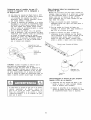
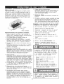
.
2.
Remove all components from the carton.
Attach the Motor Bracket on the outside of the left grill bowl panel. Align the two holes of the Bracket
with the holes on the grill bowl. Tighten securely using two Screws #10-24x3/4" UNC, Plain Washers
and Nuts provided.
Washer
#10-24 Nut
[ 11111111111111111
Rot. Screw #10-24x3/4" UNC x2
©
Rot. Washer x2
Motor Bracket
Rot. Nut #10-24 x2
r
//
Rot. Screw#10-24x3/4"
UNC with washers
and nuts
Outside of left grill
bowl panel
.
Slide the Spit through the piece of meat or poultry and the Holding Forks onto each end of the Rotisserie
Spit. Adjust spacing between Holding Forks to accommodate your food, then tighten the Thumbscrews
to keep the Holding Forks in position. Slide the Collar and Bushing onto the threaded end of the Spit.
Do not tighten the Collar Thumbscrew until the Rotisserie is placed into your grill.
Thumbscrew
3/8"x1/2"
Rot.Thumbscrew 3/8"xl/2" x3
Holding Forks
Spit
Bushing
Collar
Thumbscrew
3/8"x1/2"
2O
Page is loading ...
Page is loading ...
Page is loading ...
Page is loading ...
Page is loading ...
Page is loading ...
Page is loading ...
Page is loading ...
Page is loading ...
Page is loading ...
Page is loading ...
Page is loading ...
Page is loading ...
Page is loading ...
Page is loading ...
Page is loading ...
Page is loading ...
Page is loading ...
Page is loading ...
Page is loading ...
Page is loading ...
Page is loading ...
Page is loading ...
Page is loading ...
Page is loading ...
Page is loading ...
Page is loading ...
Page is loading ...
Page is loading ...
Page is loading ...
Page is loading ...
Page is loading ...
Page is loading ...
Page is loading ...
Page is loading ...
Page is loading ...
Page is loading ...
Page is loading ...
Page is loading ...
Page is loading ...
Page is loading ...
Page is loading ...
Page is loading ...
Page is loading ...
Page is loading ...
Page is loading ...
Page is loading ...
-
 1
1
-
 2
2
-
 3
3
-
 4
4
-
 5
5
-
 6
6
-
 7
7
-
 8
8
-
 9
9
-
 10
10
-
 11
11
-
 12
12
-
 13
13
-
 14
14
-
 15
15
-
 16
16
-
 17
17
-
 18
18
-
 19
19
-
 20
20
-
 21
21
-
 22
22
-
 23
23
-
 24
24
-
 25
25
-
 26
26
-
 27
27
-
 28
28
-
 29
29
-
 30
30
-
 31
31
-
 32
32
-
 33
33
-
 34
34
-
 35
35
-
 36
36
-
 37
37
-
 38
38
-
 39
39
-
 40
40
-
 41
41
-
 42
42
-
 43
43
-
 44
44
-
 45
45
-
 46
46
-
 47
47
-
 48
48
-
 49
49
-
 50
50
-
 51
51
-
 52
52
-
 53
53
-
 54
54
-
 55
55
-
 56
56
-
 57
57
-
 58
58
-
 59
59
-
 60
60
-
 61
61
-
 62
62
-
 63
63
-
 64
64
-
 65
65
-
 66
66
-
 67
67


Kenmore 14117678801 Owner's manual
- Category
- Barbecues & grills
- Type
- Owner's manual
- This manual is also suitable for
Ask a question and I''ll find the answer in the document
Finding information in a document is now easier with AI
in other languages
Related papers
-
Centro Barbecue Stainless 4000B Safe use User guide
-
Kenmore Stainless Steel 4 Burner Gas Grill with Oven Owner's manual
-
Kenmore Elite 141.16678800 Owner's manual
-
-
-
-
 Kenmore Elite Elite 141.17677 Owner's manual
-
-
-
 Kenmore Elite 14116673 Owner's manual


Other documents
-
 Grand Hall CSTS13ALP Owner's manual
-
Member's Mark M5205ANG Owner's manual
-
Members Mark MONARCH04ANG Owner's manual
-
Barbeques Galore B3808ALP Owner's manual
-
-
-
 Grand Cafe CGI08ALP Owner's manual
-
-
 Patio Chef SS54 Owner's manual
-
Barbeques Galore XI08ANG Owner's manual


