Mattel H0638 Owner's manual
- Category
- Motorcycles
- Type
- Owner's manual
This manual is also suitable for

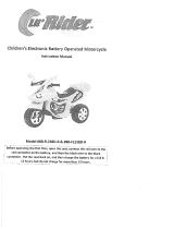
Owner's Manual
with Assembly Instructions
For Models H0638 and H4808
Harley-Davidson is a registered trademark
and the motorcycle sound is a trademark of
H-D Michigan, Inc. used under license.
In an effort to provide the best products possible, we periodically make
product modifications. Actual product may not be identical to item pictured here.
Please read this manual and save it with your original sales receipt.
Tools needed for assembly: Phillips Screwdriver, Hammer, Safety Scissors, Slotted Screwdriver
and Adjustable Wrench (no tools included).
Use only with a Power Wheels
®
12 Volt Rechargeable Battery
and a Power Wheels
®
12 Volt Charger (both included).
Sound Box requires three “AA” (LR6) alkaline batteries (batteries not included) for operation.
®

2
Table of Contents
Important Information
A Important Information . . . . . . . . . . . . . . . . . . . . . . . . . . . . . . . . . . . . . . . . . . . . . . . . . . . . . . . . . . . . . . . . . . . . .2
B Warnings and Cautions . . . . . . . . . . . . . . . . . . . . . . . . . . . . . . . . . . . . . . . . . . . . . . . . . . . . . . . . . . . . . . . . . . . .3
C Parts . . . . . . . . . . . . . . . . . . . . . . . . . . . . . . . . . . . . . . . . . . . . . . . . . . . . . . . . . . . . . . . . . . . . . . . . . . . . . . . . .4
D Parts Diagram . . . . . . . . . . . . . . . . . . . . . . . . . . . . . . . . . . . . . . . . . . . . . . . . . . . . . . . . . . . . . . . . . . . . . . . . . . .8
E Battery Charging . . . . . . . . . . . . . . . . . . . . . . . . . . . . . . . . . . . . . . . . . . . . . . . . . . . . . . . . . . . . . . . . . . . . . . . . .9
F Assembly . . . . . . . . . . . . . . . . . . . . . . . . . . . . . . . . . . . . . . . . . . . . . . . . . . . . . . . . . . . . . . . . . . . . . . . . . . . . .11
G Label Decoration . . . . . . . . . . . . . . . . . . . . . . . . . . . . . . . . . . . . . . . . . . . . . . . . . . . . . . . . . . . . . . . . . . . . . . . .27
H Battery Installation . . . . . . . . . . . . . . . . . . . . . . . . . . . . . . . . . . . . . . . . . . . . . . . . . . . . . . . . . . . . . . . . . . . . . .28
I Battery Care and Disposal . . . . . . . . . . . . . . . . . . . . . . . . . . . . . . . . . . . . . . . . . . . . . . . . . . . . . . . . . . . . . . . .30
J Caring For Your Vehicle . . . . . . . . . . . . . . . . . . . . . . . . . . . . . . . . . . . . . . . . . . . . . . . . . . . . . . . . . . . . . . . . . . .30
K Rules For Safe Driving . . . . . . . . . . . . . . . . . . . . . . . . . . . . . . . . . . . . . . . . . . . . . . . . . . . . . . . . . . . . . . . . . . .31
L How to Operate Your Vehicle . . . . . . . . . . . . . . . . . . . . . . . . . . . . . . . . . . . . . . . . . . . . . . . . . . . . . . . . . . . . . . .32
M FCC Note (United States Only) . . . . . . . . . . . . . . . . . . . . . . . . . . . . . . . . . . . . . . . . . . . . . . . . . . . . . . . . . . . . .33
N Statement of Limited Warranty . . . . . . . . . . . . . . . . . . . . . . . . . . . . . . . . . . . . . . . . . . . . . . . . . . . . . . . . . . . . .33
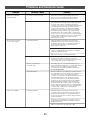
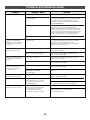
O Problems and Solutions Guide . . . . . . . . . . . . . . . . . . . . . . . . . . . . . . . . . . . . . . . . . . . . . . . . . . . . . . . . . . . . .34
•Your new vehicle requires adult assembly. Please set
aside at least 90 minutes for assembly.
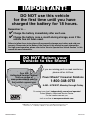
•You must charge your battery for 18 - 30 hours before
you use your vehicle for the first time.We recommend
that you start charging your battery before beginning
assembly. Please see Battery Charging beginning on
page 9 for detailed instructions.
• Read this manual carefully for important safety informa-
tion and operating instructions before using your vehicle.
Keep this manual for future reference as it contains
important information.
• This vehicle is designed for use on: grass, asphalt and
other hard surfaces; on generally level terrain; and by
children 3 years of age and older.
• Make sure children know and follow these rules for safe
driving and riding:
- always sit on the seat.
- always wear shoes.
- only 1 (one) rider at a time.
• Please note that the front wheel of the vehicle can lift
slightly off the ground during use, especially if the vehicle
is driven forward in high speed from a stopped position.
This is a normal occurrence and is not cause for alarm.
The vehicle will not tip. The rear wheel is designed to act
as a stabilizer by restricting front wheel lift, preventing
the vehicle from tipping. To prevent front wheel lift, teach
your child to start the vehicle in low speed and shift to
high speed only when already moving forward.
• Use this vehicle ONLY outdoors. Most interior flooring
can be damaged by riding this vehicle indoors.
Fisher-Price
®
will not be responsible for damage to
floor if the vehicle is used indoors.
A
•For safety reasons, your vehicle has been pre-set so
that it will operate at low speed. Note that the power
boost button on the handlebar will not operate in the
pre-set, low speed mode. You must connect the
high speed hook-up to allow operation of the
vehicle at high speed when pressing the power
boost button on the handlebar. Please see page 32
for detailed instructions.
•To prevent damaging the motors and gears, teach
your child to stop the vehicle before switching direction.
Do not tow anything behind the vehicle or overload it.
Do not exceed the maximum weight capacity of
65 lb (29.5 kg).
• If you have any questions about your Power Wheels
®
vehicle, please call our toll-free service lines at
1-800-348-0751 from 8 AM to 6 PM (EST) Monday
through Friday. Trained customer service representatives
are available to take your call in English or French.
Habla Español? Si usted tiene alguna pregunta ó
necesita asistencia llame gratis 1-800-348-0755 para los
Estados Unidos. Tenemos representantes que hablan
español para atender su llamada.
•For your convenience, Power Wheels
®
maintains an
independently owned and operated Authorized
Service Center Network with more than 400 authorized
service centers nationwide. The authorized service centers
will repair or replace parts under warranty at no extra
charge, and can perform non-warranty repairs for
a minimal charge. To find the authorized service center
nearest to you, visit us on-line at www.powerwheels.com
or call 1-800-348-0751.
• If you would like to register your vehicle, please visit us
on-line at www.powerwheels.com.

3
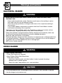
CAUTION
• In the unassembled state, this package contains small parts. Adult assembly is required.
• Use the charger in dry locations only.
WARNING
• Prevent Injuries and Deaths
• Direct Adult Supervision Required
• Keep Children Within Safe Riding Areas.
These areas must be:
- away from swimming pools and other bodies of water to prevent drownings
- generally level to prevent tipovers
- away from steps, steep inclines, cars, roads and alleys.
RIDING HAZARD
WARNING
• Battery can fall out and injure a child if vehicle tips over. Always use battery clamp.
• PREVENT FIRE
- Never modify the electrical system. Alterations could cause a fire resulting in serious
injury and could also ruin the electrical system.
- Use of the wrong type battery or charger could cause a fire or explosion resulting in
serious injury.
- Use of Power Wheels
®
components in products other than Power Wheels
®
vehicles
could cause overheating, fire or explosion.
• The battery must be handled by adults only. The battery is heavy and contains sulfuric
acid (electrolyte). Dropping the battery could result in serious injury.
•Never allow children to charge the battery. Battery charging must be done by adults only.
A child could be injured by the electricity involved in charging the battery.
• Read the safety instructions on the battery.
• Examine the battery, charger and their connectors for excessive wear or damage each time
you charge the battery. If damage or excessive wear is detected, do not use the charger or
the battery until you have replaced the worn or damaged part.
• HOT motors. Handle carefully.
Warnings and Cautions
B
ELECTRICAL HAZARD

4
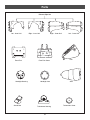
Steering Bushing - 2
Steering Stop
Parts
C
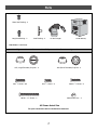
Wheel - 2
• If you experience a problem with this product, or are missing a part, please call us at 1-800-348-0751, rather than
return this product to the store.
• Please identify all parts before assembly and save all packaging material until assembly is complete to ensure that no
parts are discarded.
•Metal parts have been coated with a lubricant to protect them during shipment. Wipe all metal parts with a paper towel
to remove any excess lubricant.
T
M
Vehicle Body
Fender
Left Footboard
Vehicle Frame
Horn
Air Cleaner Cover
Primary Cover

5
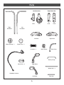
Exhaust Pipe Set
Parts
Tachometer Housing
Sound Box
Tachometer Cover
Front Fork Cover
Tank
Seat
Front Fork
Headlight Lens
Headlight Housing
Right - Outer Half
Left - Outer Half
Right - Inner Half
Left - Inner Half

6
Handgrip - 2
Parts
Right Shock SetLeft Shock Set
InnerOuter
Inner Outer
Left
Handlebar
Right
Handlebar
Left Strut
Signal Housing - 2
Right Strut
Signal Lens - 2
Wheel Axle - 2
Fork Axle
Wire Cover
Battery Clamp
Handlebar Harness
Right Mirror
Mirror Lens - 2
Mirror Clamp
Left Mirror

7
12 Volt Battery
Not Shown: Label Sheet
12-VOLT
CHARGER
12 Volt Charger
Pb
Axle Bushing - 2
Parts
All Shown Actual Size
.354 (Small Diameter) Cap Nut - 2
.354"
.437 (Large Diameter) Cap Nut - 4
For your convenience we’ve included extra fasteners!
Note: Tighten and loosen all screws with a Phillips screwdriver. Do not over-tighten the screws.
#8-32 Acorn Nut – 4
#8 x
3
/
4
" Screw – 63
#8-32 x
3
/
4
" Screw – 2
#8-32 x 1
5
/
8
" Screw – 2
.437"
#8 x
1
/
2
" Screw – 4
Short Hex Bushing - 2
Long Hex Bushing - 2

8
T
M
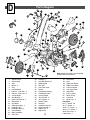
Parts Diagram
D
1. Vehicle Frame
2. Vehicle Body
3. Seat
4. Wheel - 2
5. Tank
6. Left Footboard
7. Exhaust - Inner Half - 2
8. Exhaust - Outer Half - 2
9. 12 Volt Battery
10. Axle Bushing - 2
11. Short Hex Bushing - 2
12. Wheel Axle - 2
13. Air Cleaner
14. Steering Bushing - 2
15 Headlight Lens
16. Headlight Housing
17. Left Handlebar
18. Right Handlebar
19. Front Fork
20. Handgrip - 2
21. Long Hex Bushing- 2
22. Steering Stop
23. Fork Axle
24. Front Fork Cover
25. Fender
26. Tachometer Housing
27. Tachometer Cover
28. 12 Volt Charger
29. .354 Cap Nut - 2
30. .437 Cap Nut - 4
31. Battery Clamp
32. Left Strut
33. Handlebar Harness
34. Signal Housing - 2
35. Signal Lens - 2
36. Right Mirror
37. Wire Cover
38. Horn
39. Right Inner Shock
40. Right Outer Shock
41. Left Inner Shock
42. Left Outer Shock
43. Sound Box
44. Primary Cover
45. Mirror Clamp
46. Left Mirror
47. Mirror Lens - 2
Not Shown
#8 x
3
/
4
" Screw - 63
#8 x
1
/
2
" Screw - 4
#8-32 x
3
/
4
" Screw - 2
#8-32 x 1
5
/
8
" Screw - 2
#8-32 Acorn Nut - 4
Label Sheet - 2
5
2
28
3
16
15
19
17
23
6
12
7
8
1
21
42
12
22
29
4
20
24
14
29
43
31
9
41
39
40
30
30
14
21
4
32
25
18
33
36
20
37
34
35
26
27
10
30
11
Note: Some parts shown are assembled
on both sides of the vehicle.
12-VOLT
CHARGER
44
13
38
46
45
47
47

9
Battery Charging
E
Important Notes
•Your new battery must be charged for at least
18 hours before you use it in your vehicle for
the first time.
•We recommend that you start charging your battery
before beginning assembly of your new vehicle.
•The battery must be upright while charging.
• The charger is not a toy.
• Do not short circuit the battery.
•You do not need to remove the battery from your vehicle
to recharge it.
• Before charging the battery, examine the battery case for
cracks and other damage which may cause sulfuric acid
(electrolyte) to leak during the charging process. If
damage is detected, do not charge the battery or use it
in your vehicle. Battery acid is very corrosive and can
cause severe damage to surfaces it contacts.
• Do not charge the battery on a surface (such as kitchen
counter tops) which could be damaged by the acid
contained inside the battery. Take precautions to protect
the surface on which you charge your battery.
• If your battery is old and will not accept a charge, do not
leave it in your vehicle. Always remove a dead battery
from the vehicle.
• Use only a Power Wheels
®
12 volt charger (120 VAC
60 Hz 28W with an output of 12 VDC 1200mA) to
charge your Power Wheels
®
12 volt battery.
• When replacing the 12 volt battery, use only a
Power Wheels
®
12 volt battery.
About Thermal Fuses
Yo ur Power Wheels 12 volt battery is equipped with a
built-in thermal fuse. The thermal fuse is a self-resetting
safety device which automatically “trips” and shuts down
operation of the vehicle if the vehicle is overloaded or the
driving conditions too severe. Once a fuse has “tripped”,
it will automatically reset itself after approximately 25
seconds and allow the vehicle to resume normal
operations. To avoid repeated automatic shutdowns,
do not overload the vehicle by exceeding the 65 lbs.
maximum weight capacity or by towing anything behind
the vehicle. Avoid severe driving conditions, such as
driving up slopes or running into fixed objects, which
can cause the wheels to stop spinning while power is still
being supplied to the motors and make sure your child
stops the vehicle before switching speeds or direction.
If a thermal fuse in a battery continually trips under
normal driving conditions, please contact your local
Power Wheels
®
Authorized Service Center. For the
location of the Authorized Service Center nearest to
you, please visit us on-line at www.powerwheels.com,
or call 1-800-348-0751.
CAUTION
Use the charger in dry locations only.
WARNING
• Battery can fall out and injure a child if
vehicle tips over. Always use battery clamp.
• PREVENT FIRE
- Never modify the electrical system.
Alterations could cause a fire resulting in
serious injury and could also ruin the
electrical system.
- Use of the wrong type battery or
charger could cause a fire or explosion
resulting in serious injury.
- Use of Power Wheels
®
components in
products other than Power Wheels
®
vehicles could cause overheating,
fire or explosion.
• The battery must be handled by adults only.
The battery is heavy and contains sulfuric
acid (electrolyte). Dropping the battery could
result in serious injury.
•Never allow children to charge the battery.
Battery charging must be done by adults
only. A child could be injured by the
electricity involved in charging the battery.
• Read the safety instructions on
the battery.
• Examine the battery, charger and their
connectors for excessive wear or damage
each time you charge the battery. If damage
or excessive wear is detected, do not use
the charger or the battery until you have
replaced the worn or damaged part.
ELECTRICAL HAZARD

10
Battery Charging
T
M
Pb
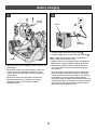
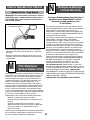
• Plug the charger connector into the battery .
• Plug the charger into a standard 120 volt wall outlet .
Note: If power flow to the wall outlet is controlled by a
switch, make sure the switch is “ON”.
•Before first-time use, charge the battery for at least 18
hours. Never charge the battery longer than 30 hours.
• Recharge the battery for at least 14 hours after each
use of your vehicle. Do not charge the battery longer
than 30 hours.
• Once the battery is charged, pull firmly on the charger
connector to disconnect it from the battery. Unplug the
charger from the wall outlet. The battery is now ready to
be installed in your vehicle. Please see the Battery
Installation section on page 29 for detailed instructions on
installing your battery. If your battery is already installed in
your vehicle, simply plug the motor harness connector
into the battery and replace the seat.
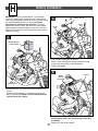
• Remove the two screws holding the battery clamp to the
vehicle body.
• Remove the battery clamp. Set the battery clamp and
screws aside. Do not throw out the battery clamp or
screws. You will use them when installing your battery
(see page 29).
• Remove the battery from the battery compartment.
• Remove and discard any cardboard in the battery
compartment which may have been added for
shipping purposes.
Battery
Charger
Connector
Battery
Battery
Clamp
1
2

11
Assembly
F
Children can be harmed by small parts,
sharp edges and sharp points in the
vehicle’s unassembled state, or by
electrical items. Care should be taken in
unpacking and assembly of the vehicle.
Children should not handle parts,
including the battery, or help in
assembly of the vehicle.
WARNING
T
M
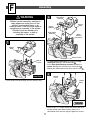
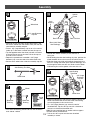
• Lift to remove the vehicle body from the vehicle frame.
Vehicle
Frame
Vehicle
Body
1
T
M
• Fit motor harness connector up through the large
rectangular opening in the vehicle body .
• Fit the high speed hook-up connector through the
square opening near the front of the vehicle body .
•Position the vehicle body on top of the vehicle frame .
Square
Opening
Motor
Harness
Connector
Vehicle Frame
Vehicle
Body
Large
Rectangular
Opening
High Speed
Hook-Up
2
T
M
•Insert six #8 x
3
/
4" screws through the vehicle body and
into the vehicle frame. Make sure the holes in the
vehicle body and frame are aligned. Tighten the screws.
Vehicle
Frame
Vehicle
Body
3
Front View

12
Assembly
T
M
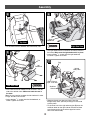
• Fit the motor harness between the vehicle body tabs.
Motor
Harness
Ta b
Ta b
Top View
• Fit the tabs on the left footboard into the slots in the left
side of the vehicle frame. Make sure both tabs are in
the slots.
Hint: You may need to squeeze the left footboard in order
to align the tabs with the slots.
•Insert two #8 x
3
/4" screws into the left footboard, as
shown. Tighten the screws.
Left
Footboard
Ta b
Ta b
Slots
4
5
T
M
• The right footboard was inserted in the vehicle frame at
the factory. Make sure the right footboard is in place.
•Insert two #8 x
3
/4
" screws into the right footboard,
as shown. Tighten the screws.
Right
Footboard
6
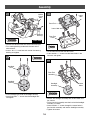
• Separate the exhaust pipe set pieces. Note the
R (right side) and L (left side) markings on the inside
of each piece.
• Fit the inner half of the right exhaust pipe (R) over the
stabilizer wheel on the right side of the vehicle. Make
sure the peg on the inner exhaust pipe fits into the
hole in the vehicle body.
T
M
Stabilizer
Wheel
Vehicle
Body Hole
Right Exhaust
Pipe - Inner Half
Peg
7
Right Side View
Left Side View

13
Assembly
T
M
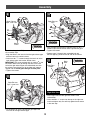
Right Exhaust
Pipe - Outer Half
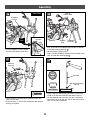
• Fit the outer half of the right exhaust pipe (R) to the
inner half of the right exhaust pipe.
Hint: Use a long-shaft Phillips screwdriver to complete
this assembly step.
• Align the holes in the inner half of the right exhaust pipe
with the holes in the vehicle frame.
•Insert four #8 x
3
/4" screws through the inner half of the
right exhaust pipe and into the vehicle frame.
IMPORTANT! The screw marked with an asterisk
*
in the
illustration above must go through the hole in the inner
half of the right exhaust pipe, the vehicle body and into
the vehicle frame. Make sure all the holes are properly
aligned and the screw goes through all three parts.
• Tighten the screws.
T
M
Vehicle
Frame
Right Exhaust
Pipe - Inner Half
*
8
9
TM
Right Exhaust
Pipe
• With the holes of both halves aligned, insert six #8 x
3
/
4"
screws to join the two halves of the right exhaust pipe.
• Tighten the screws.
• Repeat steps 7 through 10 to assemble both left
exhaust pipe (L) pieces to the left side of the vehicle.
10
Right
Strut
Right Rear
Fender
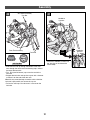
• Fit the right strut onto the right rear fender of the
vehicle body.
•Insert two #8 x
3
/
4" screws into the top of the right strut
and hand-tighten only. You will fully tighten these screws
in the next step.
11
Right Side View

Assembly
15
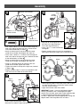
Right Strut
Tighten These Screws
Rear
Fender
#8-32 x 1
5
/8"
Machine Screw
#8-32 x
3
/4"
Machine Screw
• First, insert a #8-32 x 1
5
/8" machine screw through the
hole in the side of the right strut that is closest to the
rear of the vehicle body, as shown .
• Attach an #8-32 acorn nut to the end of the screw,
inside the rear fender. Hand-tighten the acorn nut.
• Then, insert a #8-32 x
3
/4" machine screw through the
hole in the side of the right strut that is towards the front
of the vehicle body, as shown .
• Attach an #8-32 acorn nut to the end of the screw,
inside the rear fender. Hand-tighten the acorn nut.
• Using an adjustable wrench to hold the acorn nuts
inside the rear fender, tighten the screws.
• Tighten the screws in the top of the right strut (inserted
in Step 11) .
• Repeat assembly steps 11 and 12 to assemble the left
strut to the left rear fender of the vehicle body.
12
Strut
Signal
Housing
• Slide a signal housing onto a strut.
• Bend the tab inside the signal housing down.
13
Strut
Signal
Lens Rib
Signal
Housing
Notch
• Align the rib on the signal lens with
the notch in the signal housing.
Fit the lens into the housing.
•Insert a #8 x
3
/4" screw into the lens
and tighten.
• Repeat assembly steps 13 and 14 to assemble the
other signal housing and signal lens to the other strut.
14
Signal
Lens
Signal
Housing
Bend
Ta b
Down
Back View
Wheel
1
1
2
2
4
4
3
3
Guide
Guide
Guide
Guide
• Before applying labels to the wheel, wipe it with a clean,
dry cloth to make sure it is free of dirt and oils. Make
sure your hands are clean.
• Apply labels to both sides of the wheel.
IMPORTANT! Labels 1 and 2 are designed to slightly
overlap; and labels 3 and 4 are designed to slightly
overlap. For each side, apply label 1 before applying label
2. Align the edge of label 2 with the guide marks
on label 1. Apply label 3 before applying label 4. Align the
edge of label 4 with the guide marks on label 3.
14

15
Assembly
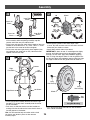
• Slide an axle bushing, flat side first, on the wheel axle.
Axle Bushing Flat Side
Wheel Axle
Wheel
Short Hex
Bushing
Short Hex
Bushing
• Fit a short hex bushing, barrel side first, into the hole in
each side of a wheel.
• Separate the fork axle from the two wheel axles. (The
fork axle is shorter than the wheels axles.) Set the fork
axle aside for assembly step 39.
• Place a .437 (large diameter) cap nut on a flat surface,
inside up. Fit the end of a wheel axle into the cap nut.
•Tap the opposite end of the wheel axle with a hammer
to secure the cap nut on the axle. Pull on the cap nut
to make sure it is secure.
• Repeat this procedure to assemble a .437 (large
diameter) cap nut to one end of the other wheel axle.
• Set one of the wheel axles aside for assembly step 53.
Wheel Axle
.437 (Large Diameter)
Cap Nut
.437"
.437 Cap Nut
16
17
18
.437 (Large
Diameter)
Cap Nut
Axle Bushing
Tube Side
Wheel Axle
• Slide an axle bushing, tube side first, onto the end of the
wheel axle. Make sure the flat end of the axle bushing
fits into the groove in the rear fork arm.
• Fit a .437 (large diameter) cap nut on the end of
the wheel axle. Tap the .437 cap nut with a hammer to
secure it on the end of the wheel axle.
Hint: You may need the help of another adult to support
the other end of the wheel axle.
• Pull on the .437 cap nut to make sure the wheel
assembly is secure.
Axle
Bushing
Vehicle
Frame
Rear Fork Arm
Groove
Rear Fork Arm
Wheel (with Short
Hex Bushings)
•Position the vehicle assembly so that the back is
facing you.
• While holding the short hex bushings in place, position the
wheel between the rear fork arms of the vehicle frame.
• Slide the wheel axle (with axle bushing) through one rear
fork arm, through the wheel (with short hex bushings) and
out through the other rear fork arm. Make sure the wheel
axle bushing fits into the groove in the rear fork arm.
Back View
.437"
.437 Cap Nut
19
20
Barrel
Side
Short Hex
Bushing

16
Assembly
T
M
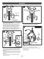
Steering
Bushing
Vehicle
Frame
Neck
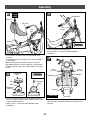
•Position the vehicle frame so that the front faces you.
• Fit a steering bushing underneath the neck of the
vehicle frame.
•Insert a #8 x
3
/4" screw into each end of the steering
bushing and tighten.
Front View
21
• Fit the headlight lens onto the headlight housing.
•Insert three #8 x
3
/4" screws into the headlight lens
and tighten.
Headlight
Lens
Headlight
Housing
22
Front Fork
Lower Hole
Lower
Hole
Front Fork
Cover
• Fit the front fork into the front fork cover.
•Insert two #8 x
1
/2" screws into the lower holes in the
front fork and tighten.
23
24
Headlight
Assembly
Center
Holes
Front Fork
Assembly
•Position the headlight assembly with the lens down on a
flat surface.
•Fit the front fork assembly onto the back of the headlight
assembly, as shown.
•Insert two #8 x
3
/4" screws through the center holes in
the front fork assembly and into the headlight assembly.
• Tighten the screws.

17
Assembly
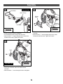
Wire Cover
Switch
Switch
Peg
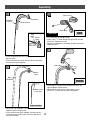
• Fit the wrapped portion of the handlebar harness into
the wire cover.
• Fit the tab on the wire cover into the notch in the switch
to lock the two parts together.
Handlebar
Harness
25
Right
Handlebar
• Locate the right handlebar. The right handlebar has an
additional hole in the grip area.
• Fit the switch to the right handlebar, making sure the
screw hole in the switch aligns with the screw hole in
the right handlebar.
Switch
Cover
26
• Fit the peg on the right mirror through the hole in the
right handlebar and the switch.
• While holding the two parts firmly together, insert
two #8 x
3
/4" screws into the switch and tighten.
28
Wire
Cover
Ta b
Switch
Notch
Additional Hole
in Grip Area
Right Handlebar
•Fit a mirror lens to the right mirror.
•Insert a #8 x
1
/
2
" screw through the right mirror into the
mirror lens. Tighten the screw.
• Repeat this procedure to assemble the other mirror lens
to the left mirror.
Right Mirror
Mirror Lens
27
Back View

18
Assembly
•Turn the front fork assembly around so the back is
facing you.
• Slide the end of the wire cover into the upper hole in the
front fork, as shown.
• While making sure the handlebar harness plug remains
inserted through only the upper hole in the front fork,
slide the right handlebar down through the upper and
lower holes in the front fork.
Front
Fork
Handlebar
Harness
Plug
Right
Handlebar
Handlebar
Harness
31
32
Back View
Front Fork
Assembly
Upper Hole in
Front Fork
End of
Wire Cover
Plug
Fork Cover
•Position the front fork so that it is upright and facing you.
•Insert the handlebar harness plug through the upper
hole in the front fork. Do not insert the plug through
the lower hole in the front fork.
Handlebar
Harness
Upper
Hole
30
DO NOT insert
the plug through
the lower hole in
the front fork!
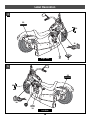
• Fit a handgrip on the end of each handlebar.
Hint: If it is difficult to slide the handgrips onto the handle-
bars, moisten the inside of the handgrips with water.
Handgrip
Handgrip
Handlebars
29
Front View

19
Assembly
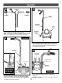
• Fit the handlebar harness plug
up through the rectangular
opening in the vehicle body.
TM
Handlebar
Harness Plug
Rectangular Opening
T
M
See
Inset
Handlebar
Harness Plug
Rectangular Opening
35
• Align the screw holes in each handlebar with the screw
holes in the front fork.
• First, insert two #8 x
3
/4" screws through the lower holes
in the front fork and into each lower hole in each handlebar
and hand tighten. Do not tighten the screws completely.
These screws will be tightened in step 55.
•Next, insert two #8 x
3
/4" screws through the upper holes
in the front fork and into each upper hole in each handlebar
and hand tighten. Do not tighten the screws completely.
These screws will be tightened in step 55.
Handlebars
Handlebar
Harness
34
•Turn the front fork around so the front is facing you.
• Slide the left handlebar through the upper and lower
holes in the front fork.
Front Fork
Left
Handlebar
33
Front View
Right Side View

20
Assembly
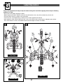
.354 (Small Diameter)
Cap Nut
Fork Axle
• Place a .354 (small diameter) cap nut on a flat surface,
inside up. Fit the end of the fork axle into the cap nut.
•Tap the opposite end of the fork axle with a hammer to
secure the cap nut on the axle. Pull on the cap nut to be
sure it is securely assembled.
.354"
.354 Cap Nut
39
T
M
Steering
Stop
Neck of
Vehicle Body
• First, fit the tab on the steering stop into the curved slot
in the lower steering bushing .
• Hold the steering stop in place.
• Then, slide the handlebar assembly on the vehicle frame
neck and over the steering stop
.
Handlebar
Assembly
38
T
M
Ta b
Handlebar
Harness
• Fit the handlebar harness behind
the tab in the vehicle frame neck.
See
Inset
Ta b
Handlebar
Harness
36
T
M
• Fit the remaining steering bushing onto the top of the
vehicle frame neck.
•Insert two #8 x
3
/4" screws into each end of the steering
bushing and tighten.
Steering
Bushing
37
Front View
Page is loading ...
Page is loading ...
Page is loading ...
Page is loading ...
Page is loading ...
Page is loading ...
Page is loading ...
Page is loading ...
Page is loading ...
Page is loading ...
Page is loading ...
Page is loading ...
Page is loading ...
Page is loading ...
Page is loading ...
Page is loading ...
Page is loading ...
Page is loading ...
Page is loading ...
-
 1
1
-
 2
2
-
 3
3
-
 4
4
-
 5
5
-
 6
6
-
 7
7
-
 8
8
-
 9
9
-
 10
10
-
 11
11
-
 12
12
-
 13
13
-
 14
14
-
 15
15
-
 16
16
-
 17
17
-
 18
18
-
 19
19
-
 20
20
-
 21
21
-
 22
22
-
 23
23
-
 24
24
-
 25
25
-
 26
26
-
 27
27
-
 28
28
-
 29
29
-
 30
30
-
 31
31
-
 32
32
-
 33
33
-
 34
34
-
 35
35
-
 36
36
-
 37
37
-
 38
38
-
 39
39


Mattel H0638 Owner's manual
- Category
- Motorcycles
- Type
- Owner's manual
- This manual is also suitable for
Ask a question and I''ll find the answer in the document
Finding information in a document is now easier with AI
Related papers
-
Power Wheels PW TRU Harley Owner's manual
-
Kawasaki PW Lil Kawasaki User manual
-
Hot Wheels MOJAVE 78473 User manual
-
Power Wheels Harley-Davidson Motorcycle Ride-on Owner's manual
-
Power Wheels Limited Edition Harley Owner's manual
-
-
-
-
-
Other documents
-
E-Collar E-Collar Receiver Battery Replacement Operating instructions
-
Hasbro Tyke Bike 1998 Operating instructions
-
AmeriHome BSLCGSET Operating instructions
-
-
-
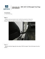 Hooke Road Jeep Wrangler Foot Pegs, Doors Off Hinge Footrest Pedal for 07-18 Jeep JK User manual
-
-
 Lifemax L97093 Operating instructions
-
Huffy Disney Minnie Battery Ride-On Owner's manual
-
 Lil Rider W41-0068 Operating instructions


