Dell AV8063801378000 User manual
- Category
- Processors
- Type
- User manual

Document Number: 326764-008
Desktop 3rd Generation Intel
®
Core™ Processor Family, Desktop
Intel
®
Pentium
®
Processor Family,
and Desktop Intel
®
Celeron
®
Processor Family
Datasheet – Volume 1 of 2
November 2013

2
Datasheet, Volume 1
INFORMATION IN THIS DOCUMENT IS PROVIDED IN CONNECTION WITH INTEL PRODUCTS. NO LICENSE, EXPRESS OR IMPLIED,
BY ESTOPPEL OR OTHERWISE, TO ANY INTELLECTUAL PROPERTY RIGHTS IS GRANTED BY THIS DOCUMENT. EXCEPT AS
PROVIDED IN INTEL'S TERMS AND CONDITIONS OF SALE FOR SUCH PRODUCTS, INTEL ASSUMES NO LIABILITY WHATSOEVER
AND INTEL DISCLAIMS ANY EXPRESS OR IMPLIED WARRANTY, RELATING TO SALE AND/OR USE OF INTEL PRODUCTS INCLUDING
LIABILITY OR WARRANTIES RELATING TO FITNESS FOR A PARTICULAR PURPOSE, MERCHANTABILITY, OR INFRINGEMENT OF ANY
PATENT, COPYRIGHT OR OTHER INTELLECTUAL PROPERTY RIGHT.
A "Mission Critical Application" is any application in which failure of the Intel Product could result, directly or indirectly, in personal
injury or death. SHOULD YOU PURCHASE OR USE INTEL'S PRODUCTS FOR ANY SUCH MISSION CRITICAL APPLICATION, YOU
SHALL INDEMNIFY AND HOLD INTEL AND ITS SUBSIDIARIES, SUBCONTRACTORS AND AFFILIATES, AND THE DIRECTORS,
OFFICERS, AND EMPLOYEES OF EACH, HARMLESS AGAINST ALL CLAIMS COSTS, DAMAGES, AND EXPENSES AND REASONABLE
ATTORNEYS' FEES ARISING OUT OF, DIRECTLY OR INDIRECTLY, ANY CLAIM OF PRODUCT LIABILITY, PERSONAL INJURY, OR DEATH
ARISING IN ANY WAY OUT OF SUCH MISSION CRITICAL APPLICATION, WHETHER OR NOT INTEL OR ITS SUBCONTRACTOR WAS
NEGLIGENT IN THE DESIGN, MANUFACTURE, OR WARNING OF THE INTEL PRODUCT OR ANY OF ITS PARTS.
Intel may make changes to specifications and product descriptions at any time, without notice. Designers must not rely on the
absence or characteristics of any features or instructions marked "reserved" or "undefined". Intel reserves these for future
definition and shall have no responsibility whatsoever for conflicts or incompatibilities arising from future changes to them. The
information here is subject to change without notice. Do not finalize a design with this information.
The products described in this document may contain design defects or errors known as errata which may cause the product to
deviate from published specifications. Current characterized errata are available on request.
Contact your local Intel sales office or your distributor to obtain the latest specifications and before placing your product order.
Copies of documents which have an order number and are referenced in this document, or other Intel literature, may be obtained
by calling 1-800-548-4725, or go to: http://www.intel.com/design/literature.htm.
No computer system can provide absolute security under all conditions. Intel
®
Trusted Execution Technology (Intel
®
TXT) requires
a computer system with Intel
®
Virtualization Technology, an Intel TXT-enabled processor, chipset, BIOS, Authenticated Code
Modules and an Intel TXT-compatible measured launched environment (MLE). The MLE could consist of a virtual machine monitor,
an OS or an application. In addition, Intel TXT requires the system to contain a TPM v1.2, as defined by the Trusted Computing
Group and specific software for some uses. For more information, see http://www.intel.com/technology/security/
Intel
®
Virtualization Technology requires a computer system with an enabled Intel® processor, BIOS, virtual machine monitor
(VMM) and, for some uses, certain computer system software enabled for it. Functionality, performance or other benefits will vary
depending on hardware and software configurations and may require a BIOS update. Software applications may not be compatible
with all operating systems. Please check with your application vendor.
Intel
®
Active Management Technology requires the computer system to have an Intel(R) AMT-enabled chipset, network hardware
and software, as well as connection with a power source and a corporate network connection. Setup requires configuration by the
purchaser and may require scripting with the management console or further integration into existing security frameworks to
enable certain functionality. It may also require modifications of implementation of new business processes. With regard to
notebooks, Intel AMT may not be available or certain capabilities may be limited over a host OS-based VPN or when connecting
wirelessly, on battery power, sleeping, hibernating or powered off. For more information, see http://www.intel.com/technology/
platform-technology/intel-amt/
Hyper-Threading Technology requires a computer system with a processor supporting HT Technology and an HT Technology-
enabled chipset, BIOS and operating system. Performance will vary depending on the specific hardware and software you use. For
more information including details on which processors support HT Technology, see http://www.intel.com/info/hyperthreading.
“Intel® Turbo Boost Technology requires a PC with a processor with Intel Turbo Boost Technology capability. Intel Turbo Boost
Technology performance varies depending on hardware, software and overall system configuration. Check with your PC
manufacturer on whether your system delivers Intel Turbo Boost Technology.For more information, see http://www.intel.com/
technology/turboboost.”
Enhanced Intel SpeedStep
®
Technology See the Processor Spec Finder or contact your Intel representative for more information.
Intel processor numbers are not a measure of performance. Processor numbers differentiate features within each processor family,
not across different processor families. See www.intel.com/products/processor_number for details.
64-bit computing on Intel architecture requires a computer system with a processor, chipset, BIOS, operating system, device
drivers and applications enabled for Intel® 64 architecture. Performance will vary depending on your hardware and software
configurations. Consult with your system vendor for more information.
Intel, Pentium, Celeron, Intel Core, and the Intel logo are trademarks of Intel Corporation in the U.S. and other countries.
*Other names and brands may be claimed as the property of others.
Copyright © 2013, Intel Corporation. All rights reserved.

Datasheet, Volume 1 3
Contents
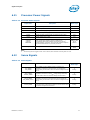
1Introduction..............................................................................................................9
1.1 Processor Feature Details ...................................................................................11
1.1.1 Supported Technologies ..........................................................................11
1.2 Interfaces ........................................................................................................11
1.2.1 System Memory Support.........................................................................11
1.2.2 PCI Express* .........................................................................................12
1.2.3 Direct Media Interface (DMI)....................................................................14
1.2.4 Platform Environment Control Interface (PECI)...........................................14
1.2.5 Processor Graphics.................................................................................14
1.2.6 Intel
®
Flexible Display Interface (Intel
®
FDI).............................................15
1.3 Power Management Support ...............................................................................15
1.3.1 Processor Core.......................................................................................15
1.3.2 System.................................................................................................15
1.3.3 Memory Controller..................................................................................15
1.3.4 PCI Express* .........................................................................................16
1.3.5 Direct Media Interface (DMI)....................................................................16
1.3.6 Processor Graphics Controller (GT) ...........................................................16
1.3.7 Thermal Management Support .................................................................16
1.4 Processor SKU Definitions...................................................................................16
1.5 Package...........................................................................................................17
1.6 Processor Compatibility......................................................................................18
1.7 Terminology .....................................................................................................19
1.8 Related Documents ...........................................................................................22
2Interfaces................................................................................................................23
2.1 System Memory Interface ..................................................................................23
2.1.1 System Memory Technology Supported.....................................................23
2.1.2 System Memory Timing Support...............................................................24
2.1.3 System Memory Organization Modes.........................................................25
2.1.3.1 Single-Channel Mode.................................................................25
2.1.3.2 Dual-Channel Mode – Intel
®
Flex Memory Technology Mode ........... 25
2.1.4 Rules for Populating Memory Slots............................................................26
2.1.5 Technology Enhancements of Intel
®
Fast Memory Access (Intel
®
FMA)..........27
2.1.5.1 Just-in-Time Command Scheduling..............................................27
2.1.5.2 Command Overlap....................................................................27
2.1.5.3 Out-of-Order Scheduling............................................................27
2.1.6 Data Scrambling ....................................................................................27
2.1.7 DDR3 Reference Voltage Generation .........................................................27
2.2 PCI Express* Interface.......................................................................................28
2.2.1 PCI Express* Architecture .......................................................................28
2.2.1.1 Transaction Layer .....................................................................29
2.2.1.2 Data Link Layer ........................................................................29
2.2.1.3 Physical Layer ..........................................................................29
2.2.2 PCI Express* Configuration Mechanism .....................................................30
2.2.3 PCI Express* Port...................................................................................31
2.2.3.1 PCI Express* Lanes Connection ..................................................31
2.3 Direct Media Interface (DMI)...............................................................................32
2.3.1 DMI Error Flow.......................................................................................32
2.3.2 Processor / PCH Compatibility Assumptions................................................32
2.3.3 DMI Link Down ......................................................................................32
2.4 Processor Graphics Controller (GT) ......................................................................33

4
Datasheet, Volume 1
2.4.1 3D and Video Engines for Graphics Processing ............................................33
2.4.1.1 3D Engine Execution Units..........................................................33
2.4.1.2 3D Pipeline...............................................................................34
2.4.1.3 Video Engine ............................................................................34
2.4.1.4 2D Engine ................................................................................35
2.4.2 Processor Graphics Display ......................................................................36
2.4.2.1 Display Planes ..........................................................................36
2.4.2.2 Display Pipes............................................................................37
2.4.2.3 Display Ports ............................................................................37
2.4.3 Intel
®
Flexible Display Interface (Intel
®
FDI) .............................................37
2.4.4 Multi Graphics Controllers Multi-Monitor Support.........................................37
2.5 Platform Environment Control Interface (PECI) ......................................................38
2.6 Interface Clocking..............................................................................................38
2.6.1 Internal Clocking Requirements ................................................................38
3 Technologies............................................................................................................39
3.1 Intel
®
Virtualization Technology (Intel
®
VT)..........................................................39
3.1.1 Intel
®
Virtualization Technology (Intel
®
VT) for
IA-32, Intel
®
64 and Intel
®
Architecture
(Intel
®
VT-x) Objectives..........................................................................39
3.1.2 Intel
®
Virtualization Technology (Intel
®
VT) for
IA-32, Intel
®
64 and Intel
®
Architecture
(Intel
®
VT-x) Features ............................................................................40
3.1.3 Intel
®
Virtualization Technology (Intel
®
VT) for Directed
I/O (Intel
®
VT-d) Objectives ....................................................................40
3.1.4 Intel
®
Virtualization Technology (Intel
®
VT) for Directed
I/O (Intel
®
VT-d) Features.......................................................................41
3.1.5 Intel
®
Virtualization Technology (Intel
®
VT) for Directed
I/O (Intel
®
VT-d) Features Not Supported..................................................41
3.2 Intel
®
Trusted Execution Technology (Intel
®
TXT) .................................................42
3.3 Intel
®
Hyper-Threading Technology (Intel
®
HT Technology)....................................42
3.4 Intel
®
Turbo Boost Technology............................................................................43
3.4.1 Intel
®
Turbo Boost Technology Frequency..................................................43
3.4.2 Intel
®
Turbo Boost Technology Graphics Frequency.....................................43
3.5 Intel
®
Advanced Vector Extensions (Intel
®
AVX)....................................................44
3.6 Security and Cryptography Technologies...............................................................44
3.6.1 Intel
®
Advanced Encryption Standard New Instructions (Intel
®
AES-NI) ........44
3.6.2 PCLMULQDQ Instruction ..........................................................................44
3.6.3 RDRAND Instruction................................................................................45
3.7 Intel
®
64 Architecture x2APIC.............................................................................45
3.8 Supervisor Mode Execution Protection (SMEP) .......................................................46
3.9 Power Aware Interrupt Routing (PAIR)..................................................................46
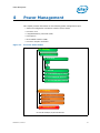
4 Power Management .................................................................................................47
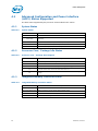
4.1 Advanced Configuration and Power Interface
(ACPI) States Supported.....................................................................................48
4.1.1 System States........................................................................................48
4.1.2 Processor Core / Package Idle States.........................................................48
4.1.3 Integrated Memory Controller States.........................................................48
4.1.4 PCI Express* Link States .........................................................................49
4.1.5 Direct Media Interface (DMI) States ..........................................................49
4.1.6 Processor Graphics Controller States .........................................................49
4.1.7 Interface State Combinations ...................................................................49
4.2 Processor Core Power Management......................................................................50
4.2.1 Enhanced Intel
®
SpeedStep
®
Technology ..................................................50
4.2.2 Low-Power Idle States.............................................................................50
4.2.3 Requesting Low-Power Idle States ............................................................52

Datasheet, Volume 1 5
4.2.4 Core C-states ........................................................................................52
4.2.4.1 Core C0 State...........................................................................52
4.2.4.2 Core C1 / C1E State..................................................................53
4.2.4.3 Core C3 State...........................................................................53
4.2.4.4 Core C6 State...........................................................................53
4.2.4.5 C-State Auto-Demotion .............................................................53
4.2.5 Package C-States...................................................................................54
4.2.5.1 Package C0..............................................................................55
4.2.5.2 Package C1/C1E .......................................................................55
4.2.5.3 Package C3 State......................................................................56
4.2.5.4 Package C6 State......................................................................56
4.3 Integrated Memory Controller (IMC) Power Management ........................................56
4.3.1 Disabling Unused System Memory Outputs ................................................56
4.3.2 DRAM Power Management and Initialization...............................................57
4.3.2.1 Initialization Role of CKE............................................................58
4.3.2.2 Conditional Self-Refresh ............................................................58
4.3.2.3 Dynamic Power Down Operation .................................................59
4.3.2.4 DRAM I/O Power Management....................................................59
4.3.3 DDR Electrical Power Gating (EPG) ...........................................................59
4.4 PCI Express* Power Management........................................................................60
4.5 DMI Power Management.....................................................................................60
4.6 Graphics Power Management ..............................................................................60
4.6.1 Intel
®
Rapid Memory Power Management (Intel
®
RMPM)
(also known as CxSR).............................................................................60
4.6.2 Intel
®
Graphics Performance Modulation Technology (Intel
®
GPMT).............. 60
4.6.3 Graphics Render C-State.........................................................................60
4.6.4 Intel
®
Smart 2D Display Technology (Intel
®
S2DDT) .................................. 61
4.6.5 Intel
®
Graphics Dynamic Frequency..........................................................61
4.7 Graphics Thermal Power Management..................................................................61
5 Thermal Management..............................................................................................63
6 Signal Description ...................................................................................................65
6.1 System Memory Interface Signals........................................................................66
6.2 Memory Reference and Compensation Signals.......................................................67
6.3 Reset and Miscellaneous Signals..........................................................................68
6.4 PCI Express*-based Interface Signals ..................................................................69
6.5 Intel
®
Flexible Display (Intel
®
FDI) Interface Signals .............................................69
6.6 Direct Media Interface (DMI) Signals....................................................................70
6.7 Phase Lock Loop (PLL) Signals ............................................................................70
6.8 Test Access Points (TAP) Signals .........................................................................70
6.9 Error and Thermal Protection Signals ...................................................................71
6.10 Power Sequencing Signals..................................................................................72
6.11 Processor Power Signals.....................................................................................73
6.12 Sense Signals...................................................................................................73
6.13 Ground and Non-Critical to Function (NCTF) Signals...............................................74
6.14 Processor Internal Pull-Up / Pull-Down Resistors....................................................74
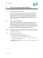
7 Electrical Specifications...........................................................................................75
7.1 Power and Ground Lands....................................................................................75
7.2 Decoupling Guidelines........................................................................................75
7.2.1 Voltage Rail Decoupling...........................................................................75
7.3 Processor Clocking (BCLK[0], BCLK#[0])..............................................................76
7.3.1 Phase Lock Loop (PLL) Power Supply.........................................................76
7.4 VCC Voltage Identification (VID)..........................................................................76
7.5 System Agent (SA) V
CC
VID................................................................................80
7.6 Reserved or Unused Signals................................................................................80

6
Datasheet, Volume 1
7.7 Signal Groups ...................................................................................................80
7.8 Test Access Port (TAP) Connection.......................................................................82
7.9 Storage Conditions Specifications.........................................................................83
7.10 DC Specifications...............................................................................................84
7.10.1 Voltage and Current Specifications............................................................84
7.11 Platform Environmental Control Interface (PECI) DC Specifications...........................90
7.11.1 PECI Bus Architecture..............................................................................90
7.11.2 DC Characteristics ..................................................................................91
7.11.3 Input Device Hysteresis...........................................................................91
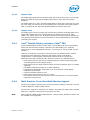
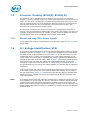
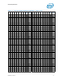
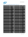
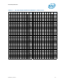
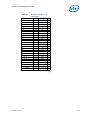
8 Processor Land and Signal Information....................................................................93
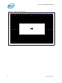
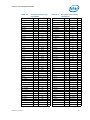
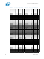
8.1 Processor Land Assignments ...............................................................................93
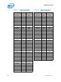
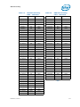
9 DDR Data Swizzling................................................................................................109
Figures
1-1 Desktop Processor Platform......................................................................................10
1-2 Desktop Processor Compatibility Diagram ..................................................................18
2-1 Intel
®
Flex Memory Technology Operation .................................................................26
2-2 PCI Express* Layering Diagram................................................................................28
2-3 Packet Flow Through the Layers ...............................................................................29
2-4 PCI Express* Related Register Structures in the Processor ...........................................30
2-5 PCI Express* Typical Operation 16 Lanes Mapping ......................................................31
2-6 Processor Graphics Controller Unit Block Diagram .......................................................33
2-7 Processor Display Block Diagram ..............................................................................36
4-1 Processor Power States ...........................................................................................47
4-2 Idle Power Management Breakdown of the Processor Cores..........................................51
4-3 Thread and Core C-State Entry and Exit.....................................................................51
4-4 Package C-State Entry and Exit ................................................................................55
7-1 Example for PECI Host-Clients Connection..................................................................90
7-2 Input Device Hysteresis...........................................................................................91
8-1 LGA Socket Land Map..............................................................................................94
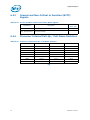
Tables
1-1 Desktop 3rd Generation Intel
®
Core™ Processor Family, Desktop Intel
®
Pentium
®
Processor Family, and Desktop Intel
®
Celeron
®
Processor Family SKUs...........16
1-2 Terminology...........................................................................................................19
1-3 Related Documents.................................................................................................22
2-1 Processor DIMM Support Summary by Product ...........................................................23
2-2 Supported UDIMM Module Configurations...................................................................24
2-3 Supported SO-DIMM Module Configurations (AIO Only)................................................24
2-4 System Memory Timing Support...............................................................................25
2-5 Reference Clock......................................................................................................38
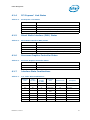
4-1 System States........................................................................................................48
4-2 Processor Core / Package State Support ....................................................................48
4-3 Integrated Memory Controller States.........................................................................48
4-4 PCI Express* Link States .........................................................................................49
4-5 Direct Media Interface (DMI) States ..........................................................................49
4-6 Processor Graphics Controller States .........................................................................49
4-7 G, S, and C State Combinations................................................................................49
4-8 Coordination of Thread Power States at the Core Level ................................................51
4-9 P_LVLx to MWAIT Conversion...................................................................................52
4-10 Coordination of Core Power States at the Package Level ..............................................54
6-1 Signal Description Buffer Types ................................................................................65

Datasheet, Volume 1 7
6-2 Memory Channel A Signals ......................................................................................66
6-3 Memory Channel B Signals ......................................................................................67
6-4 Memory Reference and Compensation.......................................................................67
6-5 Reset and Miscellaneous Signals...............................................................................68
6-6 PCI Express* Graphics Interface Signals....................................................................69
6-7 Intel
®
Flexible Display (Intel
®
FDI) Interface.............................................................69
6-8 Direct Media Interface (DMI) Signals – Processor to PCH Serial Interface .......................70
6-9 Phase Lock Loop (PLL) Signals .................................................................................70
6-10 Test Access Points (TAP) Signals ..............................................................................70
6-11 Error and Thermal Protection Signals ........................................................................71
6-12 Power Sequencing Signals.......................................................................................72
6-13 Processor Power Signals..........................................................................................73
6-14 Sense Signals........................................................................................................73
6-15 Ground and Non-Critical to Function (NCTF) Signals....................................................74
6-16 Processor Internal Pull-Up / Pull-Down Resistors.........................................................74
7-1 VR 12.0 Voltage Identification Definition....................................................................77
7-2 Signal Groups 1 .....................................................................................................81
7-3 Storage Condition Ratings .......................................................................................83
7-4 Processor Core Active and Idle Mode DC Voltage and Current Specifications...................84
7-5 Processor System Agent I/O Buffer Supply DC Voltage and Current Specifications...........86
7-6 Processor Graphics VID based (V
AXG
) Supply DC Voltage and Current Specifications........87
7-7 DDR3 Signal Group DC Specifications........................................................................87
7-8 Control Sideband and TAP Signal Group DC Specifications ...........................................89
7-9 PCI Express* DC Specifications ................................................................................89
7-10 PECI DC Electrical Limits .........................................................................................91
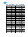
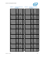
8-1 Processor Land List by Land Name............................................................................95
9-1 DDR Data Swizzling Table – Channel A.................................................................... 110
9-2 DDR Data Swizzling table – Channel B .................................................................... 111

8
Datasheet, Volume 1
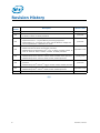
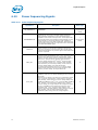
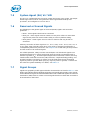
Revision History
§ §
Revision
Number
Description Revision Date
001 • Initial release April 2012
002
• Added Desktop 3rd Generation Intel
®
Core™ i5-3470T, i5-3470, i5-3470S,
i5-3475S, i5-3570, i5-3570S processors
June 2012
003
• Updated Section 1.2.2, PCI Express*
• Updated Section 2.1.1, System Memory Technology Supported
• Updated Table 7-4, “Processor Core Active and Idle Mode DC Voltage and
Current Specifications”. Added 65 W to 2011C.
June 2012
004
• Minor edits throughout for clarity
• Added Intel Pentium G2120 and G2100T processors
• Added Desktop 3rd Generation Intel
®
Core™ i3-3220, i3-3220T, i3-3225, i3-
3240, i3-3240T, i5-3330, i5-3330S, i5-3335S, i5-3350P processors
September 2012
005
• Added Desktop 3rd Generation Intel
®
Core™ i3-3210 processor
• Added Desktop Intel
®
Pentium
®
G2130, G2020, G2020T, G2010 processor
• Added Desktop Intel
®
Celeron
®
G1620, G1610, G1610T processor
January 2013
006
• Added Desktop 3rd Generation Intel
®
Core™ i3-3250, i3-3250T, i3-3245
processor
• Added Desktop Intel
®
Pentium
®
G2140, G2120T, G2030, G2030T processor
June 2013
007
• Added Desktop 3rd Generation Intel
®
Core™ i5-3340, i5-3340S processor
• Added Desktop Intel
®
Celeron
®
G1630, G1620, G1620T processor
September 2013
008 • Added Desktop Intel Pentium Processor A1018 November 2013

Datasheet, Volume 1 9
Introduction
1 Introduction
The Desktop 3rd Generation Intel
®
Core™ processor family, Desktop Intel
®
Pentium
®
processor family, and Desktop Intel
®
Celeron
®
processor family are the next
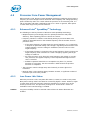
generation of 64-bit, multi-core processors built on 22-nanometer process technology.
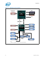
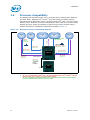
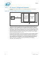
The processors are designed for a two-chip platform. The two-chip platform consists of
a processor and a Platform Controller Hub (PCH) and enables higher performance,
lower cost, easier validation, and improved x-y footprint. The processor includes an
Integrated Display Engine, Processor Graphics, PCI Express ports, and an Integrated
Memory Controller. The processor is designed for desktop platforms. The processor
offers either 6 or 16 graphic execution units (EUs). The number of EU engines
supported may vary between processor SKUs. The processor is offered in an 1155-land
LGA package (H2). Figure 1-1 shows an example desktop platform block diagram.
The Datasheet provides DC specifications, pinout and signal definitions, interface
functional descriptions, and additional feature information pertinent to the
implementation and operation of the processor on its respective platform.
Note: Throughout this document, the Intel
®
6 / 7 Series Chipset Platform Controller Hub may
be referred to as “PCH”.
Note: Throughout this document, the Desktop 3rd Generation Intel
®
Core™ processor family,
Desktop Intel
®
Pentium
®
processor family, and Desktop Intel
®
Celeron
®
processor
family may be referred to simply as “processor”.
Note: Throughout this document, the Desktop 3rd Generation Intel
®
Core™ processor family,
Desktop Intel
®
Pentium
®
processor family, and Desktop Intel
®
Celeron
®
processor
family refer to the processor SKUs listed in
Table 1-1.
Note: Some processor features are not available on all platforms. Refer to the processor
specification update for details.
Note: The term “DT” refers to desktop platforms.

Introduction
10 Datasheet, Volume 1
Figure 1-1. Desktop Processor Platform
I
n
t
e
l
®
F
l
e
x
i
b
l
e
D
i
s
p
l
a
y
I
n
t
e
r
f
a
c
e
DMI2 x4
Discrete
Graphics (PEG)
Analog CRT
Gigabit
Network Connection
USB 2.0 / USB 3.0
1
Intel
®
HD Audio
FWH
Super I/O
Serial ATA
DDR3
PCI Express* 3.0
1 x16 or 2x8
8 PCI Express* 2.0
x1 Ports
(5 GT/s)
SPI
Digital Display x 3
PCI Express*
SPI Flash x 2
LPC
SMBUS 2.0
GPIO
WiFi / WiMax
Controller Link 1
PECI
Intel
®
6/7 Series
Chipset Families
Intel
®
Management
Engine
Intel
®
Processor
Note:
1. USB 3.0 is supported on the Intel
®
7 Series Chipset family only.

Datasheet, Volume 1 11
Introduction
1.1 Processor Feature Details
• Four or two execution cores
• A 32-KB instruction and 32-KB data first-level cache (L1) for each core
• A 256-KB shared instruction / data second-level cache (L2) for each core
• Up to 8-MB shared instruction / data third-level cache (L3), shared among all cores
1.1.1 Supported Technologies
•Intel
®
Virtualization Technology (Intel
®
VT) for Directed I/O (Intel
®
VT-d)
•Intel
®
Virtualization Technology (Intel
®
VT) for IA-32, Intel
®
64 and Intel
®
Architecture (Intel
®
VT-x)
Intel
®
Active Management Technology (Intel
®
AMT) 8.0
•Intel
®
Trusted Execution Technology (Intel
®
TXT)
•Intel
®
Streaming SIMD Extensions 4.1 (Intel
®
SSE4.1)
•Intel
®
Streaming SIMD Extensions 4.2 (Intel
®
SSE4.2)
•Intel
®
Hyper-Threading Technology (Intel
®
HT Technology)
•Intel
®
64 Architecture
• Execute Disable Bit
•Intel
®
Turbo Boost Technology
•Intel
®
Advanced Vector Extensions (Intel
®
AVX)
•Intel
®
Advanced Encryption Standard New Instructions (Intel
®
AES-NI)
• PCLMULQDQ Instruction
• RDRAND instruction for random number generation
• SMEP – Supervisor Mode Execution Protection
• PAIR – Power Aware Interrupt Routing
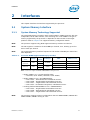
1.2 Interfaces
1.2.1 System Memory Support
• Two channels of DDR3 Unbuffered Dual In-Line Memory Modules (UDIMM) or DDR3
Unbuffered Small Outline Dual In-Line Memory Modules (SO-DIMM) with a
maximum of two DIMMs per channel
• Single-channel and dual-channel memory organization modes
• Data burst length of eight for all memory organization modes
• Memory DDR3 data transfer rates of 1333 MT/s and 1600 MT/s. The DDR3 data
transfer rates supported by the processor is dependent on the PCH SKU in the
target platform:
— Desktop PCH platforms support 1333 MT/s and 1600 MT/s for One DIMM and
Two DIMMs per channel
— All In One platforms (AIO) support 1333 MT/s and 1600 MT/s for One DIMM
and Two DIMMs per channel
• 64-bit wide channels
• System Memory Interface I/O Voltage of 1.5 V
• DDR3 and DDR3L DIMMs/DRAMs running at 1.5 V
• No support for DDR3L DIMMs/DRAMS running at 1.35 V

Introduction
12 Datasheet, Volume 1
• Support memory configurations that mix DDR3 DIMMs/DRAMs with DDR3L
DIMMs/DRAMs running at 1.5 V
• The type of the DIMM modules supported by the processor is dependent on the PCH
SKU in the target platform:
— Desktop PCH platforms support non-ECC UDIMMs only
— All In One platforms (AIO) support SO-DIMMs
• Theoretical Maximum Memory Bandwidth:
— 10.6 GB/s in single-channel mode or 21.3 GB/s in dual-channel mode assuming
DDR3 1333 MT/s
— 12.8 GB/s in single-channel mode or 25.6 GB/s in dual-channel mode assuming
DDR3 1600 MT/s
• Processor on-die Reference Voltage (VREF) generation for both DDR3 Read
(RDVREF) and Write (VREFDQ)
• 1Gb, 2Gb, and 4Gb DDR3 DRAM device technologies are supported
— Using 4Gb DRAM device technologies, the largest memory capacity possible is
32
GB, assuming Dual Channel Mode with four x8 dual ranked DIMM memory
configuration
• Up to 64 simultaneous open pages, 32 per channel (assuming 8 ranks of 8 bank
devices)
• Command launch modes of 1N/2N
• On-Die Termination (ODT)
• Asynchronous ODT
•Intel
®
Fast Memory Access (Intel
®
FMA):
— Just-in-Time Command Scheduling
—Command Overlap
— Out-of-Order Scheduling
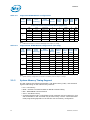
1.2.2 PCI Express*
• The PCI Express* lanes (PEG[15:0] TX and RX) are fully-compliant to the PCI
Express Base Specification, Revision 3.0, including support for 8.0 GT/s transfer
speeds.
• Processor with Desktop PCH Supports (may vary depending on PCH SKUs)
• PCI Express* supported configurations in desktop products
• The port may negotiate down to narrower widths
— Support for x16/x8/x4/x2/x1 widths for a single PCI Express* mode
• 2.5 GT/s, 5.0 GT/s and 8.0 GT/s PCI Express* frequencies are supported
• Gen1 Raw bit-rate on the data pins Gen 2 Raw bit-rate on the data pins of 5.0 GT/s,
resulting in a real bandwidth per pair of 500 MB/s given the 8b/10b encoding used
Configuration Organization Desktop
1
1x8
Graphics, I/O
2x4
2 2x8 Graphics, I/O
3 1x16 Graphics, I/O

Datasheet, Volume 1 13
Introduction
to transmit data across this interface. This also does not account for packet
overhead and link maintenance.
• Maximum theoretical bandwidth on the interface of 8 GB/s in each direction
simultaneously, for an aggregate of 16 GB/s when x16 Gen 2
• Gen 3 raw bit-rate on the data pins of 8.0 GT/s, resulting in a real bandwidth per
pair of 984 MB/s using 128b/130b encoding to transmit data across this interface.
This also does not account for packet overhead and link maintenance.
• Maximum theoretical bandwidth on the interface of 16 GB/s in each direction
simultaneously, for an aggregate of 32 GB/s when x16 Gen 3
• Hierarchical PCI-compliant configuration mechanism for downstream devices
• Traditional PCI style traffic (asynchronous snooped, PCI ordering)
• PCI Express* extended configuration space. The first 256 bytes of configuration
space aliases directly to the PCI Compatibility configuration space. The remaining
portion of the fixed 4-KB block of memory-mapped space above that (starting at
100h) is known as extended configuration space.
• PCI Express* Enhanced Access Mechanism. Accessing the device configuration
space in a flat memory mapped fashion.
• Automatic discovery, negotiation, and training of link out of reset
• Traditional AGP style traffic (asynchronous non-snooped, PCI-X Relaxed ordering)
• Peer segment destination posted write traffic (no peer-to-peer read traffic) in
Virtual Channel 0:
— DMI -> PCI Express* Port 0
• 64-bit downstream address format; however, the processor never generates an
address above 64 GB (Bits 63:36 will always be zeros)
• 64-bit upstream address format; however, the processor responds to upstream
read transactions to addresses above 64 GB (addresses where any of Bits 63:36
are nonzero) with an Unsupported Request response. Upstream write transactions
to addresses above 64
GB will be dropped.
• Re-issues Configuration cycles that have been previously completed with the
Configuration Retry status
• PCI Express* reference clock is 100-MHz differential clock
• Power Management Event (PME) functions
• Dynamic width capability
• Message Signaled Interrupt (MSI and MSI-X) messages
• Polarity inversion
Note: The processor does not support PCI Express* Hot-Plug.

Introduction
14 Datasheet, Volume 1
1.2.3 Direct Media Interface (DMI)
• DMI 2.0 support
• Four lanes in each direction
• 5 GT/s point-to-point DMI interface to PCH is supported
• Raw bit-rate on the data pins of 5.0 Gb/s, resulting in a real bandwidth per pair of
500 MB/s given the 8b/10b encoding used to transmit data across this interface.
Does not account for packet overhead and link maintenance.
• Maximum theoretical bandwidth on interface of 2 GB/s in each direction
simultaneously, for an aggregate of 4 GB/s when DMI x4
• Shares 100-MHz PCI Express* reference clock
• 64-bit downstream address format; however, the processor never generates an
address above 64 GB (Bits 63:36 will always be zeros)
• 64-bit upstream address format, but the processor responds to upstream read
transactions to addresses above 64 GB (addresses where any of Bits 63:36 are
nonzero) with an Unsupported Request response. Upstream write transactions to
addresses above 64 GB will be dropped.
• Supports the following traffic types to or from the PCH:
—DMI -> DRAM
— DMI -> processor core (Virtual Legacy Wires (VLWs), Resetwarn, or MSIs only)
— Processor core -> DMI
• APIC and MSI interrupt messaging support:
— Message Signaled Interrupt (MSI and MSI-X) messages
• Downstream SMI, SCI and SERR error indication
• Legacy support for ISA regime protocol (PHOLD / PHOLDA) required for parallel
port DMA, floppy drive, and LPC bus masters
• DC coupling – no capacitors between the processor and the PCH
• Polarity inversion
• PCH end-to-end lane reversal across the link
• Supports Half Swing “low-power / low-voltage”
1.2.4 Platform Environment Control Interface (PECI)
The PECI is a one-wire interface that provides a communication channel between a
PECI client (the processor) and a PECI master. The processor supports the PECI 3.0
Specification.
1.2.5 Processor Graphics
• The Processor Graphics contains a refresh of the seventh generation graphics core
enabling substantial gains in performance and lower power consumption. Up to
16
EU support.
• Next Generation Intel Clear Video Technology HD Support is a collection of video
playback and enhancement features that improve the end user’s viewing
experience
— Encode / transcode HD content
— Playback of high definition content including Blu-ray Disc*
— Superior image quality with sharper, more colorful images
— Playback of Blu-ray Disc* S3D content using HDMI* (V.1.4 with 3D)

Datasheet, Volume 1 15
Introduction
• DirectX* Video Acceleration (DXVA) support for accelerating video processing
— Full AVC/VC1/MPEG2 HW Decode
• Advanced Scheduler 2.0, 1.0, XPDM support
• Windows* 7, Windows* XP, OSX, Linux OS Support
• DirectX* 11, DirectX* 10.1, DirectX* 10, DirectX* 9 support
•OpenGL* 3.0 support
• Switchable Graphics support on Desktop AIO platforms with MxM solutions only
1.2.6 Intel
®
Flexible Display Interface (Intel
®
FDI)
• For SKUs with graphics, carries display traffic from the Processor Graphics in the
processor to the legacy display connectors in the PCH
• Based on DisplayPort standard
• The two Intel FDI links are capable of being configured to support three
independent channels, one for each display pipeline
• There are two Intel FDI channels, each one consists of four unidirectional
downstream differential transmitter pairs:
— Scalable down to 3X, 2X, or 1X based on actual display bandwidth
requirements
— Fixed frequency 2.7 GT/s data rate
• Two sideband signals for display synchronization:
— FDI_FSYNC and FDI_LSYNC (Frame and Line Synchronization)
• One Interrupt signal used for various interrupts from the PCH:
— FDI_INT signal shared by both Intel FDI Links
• PCH supports end-to-end lane reversal across both links
• Common 100-MHz reference clock
1.3 Power Management Support
1.3.1 Processor Core
• Full support of ACPI C-states as implemented by the following processor C-states:
— C0, C1, C1E, C3, C6
• Enhanced Intel SpeedStep Technology
1.3.2 System
• S0, S3, S4, S5
1.3.3 Memory Controller
• Conditional self-refresh (Intel
®
Rapid Memory Power Management (Intel
®
RMPM))
• Dynamic power down
1.3.4 PCI Express*
• L0s and L1 ASPM power management capability

Introduction
16 Datasheet, Volume 1
1.3.5 Direct Media Interface (DMI)
• L0s and L1 ASPM power management capability
1.3.6 Processor Graphics Controller (GT)
•Intel
®
Rapid Memory Power Management (Intel
®
RMPM) – CxSR
•Intel
®
Graphics Performance Modulation Technology (Intel
®
GPMT)
•Intel
®
Smart 2D Display Technology (Intel
®
S2DDT)
• Graphics Render C-State (RC6)
1.3.7 Thermal Management Support
• Digital Thermal Sensor
• Intel Adaptive Thermal Monitor
• THERMTRIP# and PROCHOT# support
• On-Demand Mode
• Memory Thermal Throttling
• External Thermal Sensor (TS-on-DIMM and TS-on-Board)
• Render Thermal Throttling
• Fan speed control with DTS
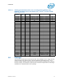
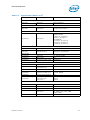
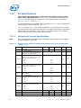
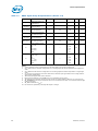
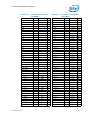
1.4 Processor SKU Definitions
Table 1-1. Desktop 3rd Generation Intel
®
Core™ Processor Family, Desktop Intel
®
Pentium
®
Processor Family, and Desktop Intel
®
Celeron
®
Processor Family
SKUs (Sheet 1 of 2)
Processor
Number
TDP
(W)
IA LFM
Frequency
IA Frequency range GT Frequency range
T
jMAX
(°C)
i7-3770T 45 1600 MHz 2.5 GHz up to 3.7 GHz 650 MHz up to 1150 MHz 94
i7-3770S 65 1600 MHz 3.1 GHz up to 3.9 GHz 650 MHz up to 1150 MHz 103
i7-3770K 77 1600 MHz 3.5 GHz up to 3.9 GHz 650 MHz up to 1150 MHz 105
i7-3770 77 1600 MHz 3.4 GHz up to 3.9 GHz 650 MHz up to 1150 MHz 105
i5-3570T 45 1600 MHz 2.3 GHz up to 3.3 GHz 650 MHz up to 1150 MHz 94
i5-3570S 65 1600 MHz 3.1 GHz up to 3.8 GHz 650 MHz up to 1150 MHz 103
i5-3570K 77 1600 MHz 3.4 GHz up to 3.8 GHz 650 MHz up to 1150 MHz 105
i5-3570 77 1600 MHz 3.4 GHz up to 3.8 GHz 650 MHz up to 1150 MHz 105
i5-3550S 65 1600 MHz 3 GHz up to 3.7 GHz 650 MHz up to 1150 MHz 103
i5-3550 77 1600 MHz 3.3 GHz up to 3.7 GHz 650 MHz up to 1150 MHz 105
i5-3475S 65 1600 MHz 2.9 GHz up to 3.6 GHz 650 MHz up to 1100 MHz 103
i5-3470S 65 1600 MHz 2.9 GHz up to 3.6 GHz 650 MHz up to 1100 MHz 103
i5-3470T 35 1600 MHz 2.9 GHz up to 3.6 GHz 650 MHz up to 1100 MHz, 91
i5-3470 77 1600 MHz 3.2 GHz up to 3.6 GHz 650 MHz up to 1100 MHz 105
i5-3450S 65 1600 MHz 2.8 GHz up to 3.5 GHz 650 MHz up to 1100 MHz 103
i5-3450 77 1600 MHz 3.1 GHz up to 3.5 GHz 650 MHz up to 1100 MHz 105
i5-3350P 69 1600 MHz 3.1 GHZ up to 3.3 GHZ N/A 105
i5-3340 77 1600 MHz 3.1 GHZ up to 3.3 GHZ 650 MHz up to 1050 MHz 105

Datasheet, Volume 1 17
Introduction
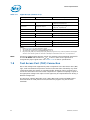
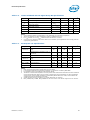
1.5 Package
The processor socket type is noted as LGA 1155. The package is a 37.5 x 37.5 mm Flip
Chip Land Grid Array (FCLGA 1155). See the Desktop 3rd Generation Intel
®
Core™
Processor Family, Desktop Intel
®
Pentium
®
Processor Family, Desktop Intel
®
Celeron
®
Processor Family, and LGA1155 Socket Thermal / Mechanical Specifications and Design
Guidelines for complete details on the package.
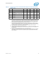
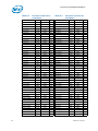
i5-3340S 65 1600 MHz 3.0 GHZ up to 3.3 GHZ 650 MHz up to 1050 MHz 103
i5-3335S 65 1600 MHz 2.7 GHz up to 3.2 GHz 650 MHz up to 1050 MHz 103
i5-3330S 65 1600 MHz 2.7 GHz up to 3.2 GHz 650 MHz up to 1050 MHz 103
i3-3250T 35 1600 MHz N/A 650 MHz up to 1050 MHz 91
i3-3250 55 1600 MHz N/A 650 MHz up to 1050 MHz 105
i3-3245 55 1600 MHz N/A 650 MHz up to 1050 MHz 105
i5-3330 77 1600 MHz 3 GHz up to 3.2 GHz 650 MHz up to 1050 MHz 105
i3-3240T 35 1600 MHz Up to 3.0 GHz 650 MHz up to 1050 MHz 91
i3-3240 55 1600 MHz Up to 3.4 GHz 650 MHz up to 1050 MHz 105
i3-3225 55 1600 MHz Up to 3.3 GHz 650 MHz up to 1050 MHz 105
i3-3220T 35 1600 MHz Up to 2.8 GHz 650 MHz up to 1050 MHz 91
i3-3220 55 1600 MHz Up to 3.3 GHz 650 MHz up to 1050 MHz 105
i3-3210 55 1600 MHz Up to 3.2 GHz 650 MHz up to 1050 MHz 105
G2140 55 1600 MHz N/A 650 MHz up to 1050 MHz 105
G2130 55 1600 MHz Up to 3.2 GHz 650 MHz up to 1050 MHz 105
G2120T 35 1600 MHz N/A 650 MHz up to 1050 MHz 91
G2120 55 1600 MHz 3.1 GHZ 650 MHZ up to 1.05 GHZ 105
G2100T 35 1600 MHz 2.6 GHZ 650 MHZ up to 1.05 GHZ 91
G2030T 35 1600 MHz N/A 650 MHz up to 1050 MHz 91
G2030 35 1600 MHz N/A 650 MHz up to 1050 MHz 105
G2020 55 1600 MHz 2.9 GHZ 650 MHZ up to 1050 MHz 105
G2020T 35 1600 MHz 2.5 GHZ 650 MHZ up to 1050 MHz 91
G2010 55 1600 MHz 2.8 GHZ 650 MHZ up to 1050 MHz 105
G1630 55 1600 MHz 2.8 GHZ 650 MHZ up to 1050 MHz 105
G1620 55 1600 MHz 2.7 GHZ 650 MHZ up to 1050 MHz 105
G1620T 35 1600 MHz 2.4 GHZ 650 MHZ up to 1050 MHz 91
G1610 55 1600 MHz 2.6 GHZ 650 MHZ up to 1050 MHz 105
G1610T 35 1600 MHz 2.3 GHZ 650 MHZ up to 1050 MHz 91
A1018 35 1600 MHz 2.1 GHz 650 MHz up to 1 GHz 105
Table 1-1. Desktop 3rd Generation Intel
®
Core™ Processor Family, Desktop Intel
®
Pentium
®
Processor Family, and Desktop Intel
®
Celeron
®
Processor Family
SKUs (Sheet 2 of 2)
Processor
Number
TDP
(W)
IA LFM
Frequency
IA Frequency range GT Frequency range
T
jMAX
(°C)

Introduction
18 Datasheet, Volume 1
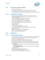
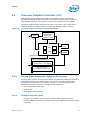
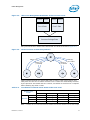
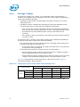
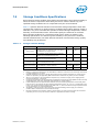
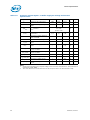
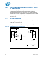
1.6 Processor Compatibility
The Desktop 3rd Generation Intel
®
Core™ processor family, Desktop Intel
®
Pentium
®
processor family, Desktop Intel
®
Celeron
®
processor Family has specific platform
requirements that differentiate it from a 2nd Generation Intel
®
Core™ processor family
Desktop, Intel
®
Pentium
®
processor family Desktop, Intel
®
Celeron
®
processor Family
Desktop processor. Platforms intending to support both processor families need to
address the platform compatibility requirements detailed in Figure 1-2.
Notes:
1. G2_Core = 2nd Generation Intel
®
Core™ processor family Desktop, Intel
®
Pentium
®
processor
family Desktop, Intel
®
Celeron
®
processor family Desktop,
2. G3_Core = Desktop 3rd Generation Intel
®
Core™ processor family, Desktop Intel
®
Pentium
®
processor, Desktop Intel
®
Celeron
®
processor family
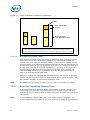
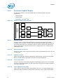
Figure 1-2. Desktop Processor Compatibility Diagram
2 x 330 µF
2 x 330 µF +
1 placeholder
VCCIO
VR
VDDQ
VR
VCore
VR
VCCSA
VR
VAXG
VR
DDR3
DDR3
G2_Core: 1.5 V
G3_Core: 1.5 V
G2_Core: 1.05 V
G3_Core: 1.05 V
VCCIO_SEL#
G2_Core: ‘1’
G3_Core: ‘1’
Processor
PCH
VCCSA_VID
G2_Core: ‘0’
G3_Core: ‘0’
G2_Core: 0.925 V
G3_Core: 0.925 V
PEG AC Decoupling
PEG Gen 1,2 – 100 nF
PEG Gen 1,2,3 – 220 nF
*VAXG: 2 ph required for
some of the SKUs
SVID
PROC_SELECT#
G2_Core: ‘1’
G3_Core: ‘0’
Controls DMI
And FDI
termination
DF_TVS

Datasheet, Volume 1 19
Introduction
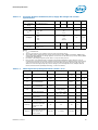
1.7 Terminology
Table 1-2. Terminology (Sheet 1 of 3)
Term Description
ACPI Advanced Configuration and Power Interface
ADB Automatic Display Brightness
APD Active Power Down
ASPM Active State Power Management
BGA Ball Grid Array
BLT Block Level Transfer
CLTT Closed Loop Thermal Throttling
CRT Cathode Ray Tube
cTDP Configurable Thermal Design Power
DDDR3L-RS DDR3L Reduced Standby Power
DDR3 Third-generation Double Data Rate SDRAM memory technology
DDR3L DDR3 Low Voltage
DMA Direct Memory Access
DMI Direct Media Interface
DP DisplayPort*
DPST Display Power Savings Technology
DTS Digital Thermal Sensor
EC Embedded Controller
ECC Error Correction Code
eDP* Embedded DisplayPort*
Enhanced Intel
®
SpeedStep
®
Technology
Technology that provides power management capabilities to laptops.
EPG Electrical Power Gating
EU Execution Unit
Execute Disable Bit
The Execute Disable bit allows memory to be marked as executable or non-executable,
when combined with a supporting operating system. If code attempts to run in non-
executable memory the processor raises an error to the operating system. This feature
can prevent some classes of viruses or worms that exploit buffer overrun
vulnerabilities and can thus help improve the overall security of the system. See the
Intel
®
64 and IA-32 Architectures Software Developer's Manuals for more detailed
information.
HDMI* High Definition Multimedia Interface
HFM High Frequency Mode
IMC Integrated Memory Controller
Intel
®
64 Technology 64-bit memory extensions to the IA-32 architecture
Intel
®
DPST Intel
®
Display Power Saving Technology
Intel
®
FDI Intel
®
Flexible Display Interface
Intel
®
TXT Intel
®
Trusted Execution Technology
Intel
®
Virtualization
Technology
Processor virtualization which when used in conjunction with Virtual Machine Monitor
software enables multiple, robust independent software environments inside a single
platform.

Introduction
20 Datasheet, Volume 1
Intel
®
VT-d
Intel
®
Virtualization Technology (Intel
®
VT) for Directed I/O. Intel VT-d is a hardware
assist, under system software (Virtual Machine Manager or operating system) control,
for enabling I/O device virtualization. Intel VT-d also brings robust security by
providing protection from errant DMAs by using DMA remapping, a key feature of Intel
VT-d.
IOV I/O Virtualization
ISA
Industry Standard Architecture. This is a legacy computer bus standard for IBM PC
compatible computers.
ITPM Integrated Trusted Platform Module
LCD Liquid Crystal Display
LFM Low Frequency Mode
LPC Low Pin Count
LPM Low Power Mode
LVDS
Low Voltage Differential Signaling. A high speed, low power data transmission
standard used for display connections to LCD panels.
MLE Measured Launched Environment
MSI Message Signaled Interrupt
NCTF
Non-Critical to Function. NCTF locations are typically redundant ground or non-critical
reserved, so the loss of the solder joint continuity at end of life conditions will not
affect the overall product functionality.
ODT On-Die Termination
PAIR Power Aware Interrupt Routing
PCH
Platform Controller Hub. The chipset with centralized platform capabilities including the
main I/O interfaces along with display connectivity, audio features, power
management, manageability, security and storage features.
PECI Platform Environment Control Interface.
PEG
PCI Express* Graphics. External Graphics using PCI Express* Architecture. A high-
speed serial interface whose configuration is software compatible with the existing PCI
specifications.
PGA Pin Grid Array
PLL Phase Lock Loop
PME Power Management Event
PPD Precharged Power Down
Processor The 64-bit, single-core or multi-core component (package).
Processor Core
The term “processor core” refers to Si die itself that can contain multiple execution
cores. Each execution core has an instruction cache, data cache, and 256-KB L2 cache.
All execution cores share the L3 cache.
Processor Graphics Intel Processor Graphics
Rank
A unit of DRAM corresponding four to eight devices in parallel, ignoring ECC. These
devices are usually, but not always, mounted on a single side of a SO-DIMM.
SCI System Control Interrupt. Used in ACPI protocol.
Intel SDRRS
Technology
Intel Seamless Display Refresh Rate Switching Technology
SMEP Supervisor Mode Execution Protection
Table 1-2. Terminology (Sheet 2 of 3)
Term Description
Page is loading ...
Page is loading ...
Page is loading ...
Page is loading ...
Page is loading ...
Page is loading ...
Page is loading ...
Page is loading ...
Page is loading ...
Page is loading ...
Page is loading ...
Page is loading ...
Page is loading ...
Page is loading ...
Page is loading ...
Page is loading ...
Page is loading ...
Page is loading ...
Page is loading ...
Page is loading ...
Page is loading ...
Page is loading ...
Page is loading ...
Page is loading ...
Page is loading ...
Page is loading ...
Page is loading ...
Page is loading ...
Page is loading ...
Page is loading ...
Page is loading ...
Page is loading ...
Page is loading ...
Page is loading ...
Page is loading ...
Page is loading ...
Page is loading ...
Page is loading ...
Page is loading ...
Page is loading ...
Page is loading ...
Page is loading ...
Page is loading ...
Page is loading ...
Page is loading ...
Page is loading ...
Page is loading ...
Page is loading ...
Page is loading ...
Page is loading ...
Page is loading ...
Page is loading ...
Page is loading ...
Page is loading ...
Page is loading ...
Page is loading ...
Page is loading ...
Page is loading ...
Page is loading ...
Page is loading ...
Page is loading ...
Page is loading ...
Page is loading ...
Page is loading ...
Page is loading ...
Page is loading ...
Page is loading ...
Page is loading ...
Page is loading ...
Page is loading ...
Page is loading ...
Page is loading ...
Page is loading ...
Page is loading ...
Page is loading ...
Page is loading ...
Page is loading ...
Page is loading ...
Page is loading ...
Page is loading ...
Page is loading ...
Page is loading ...
Page is loading ...
Page is loading ...
Page is loading ...
Page is loading ...
Page is loading ...
Page is loading ...
Page is loading ...
Page is loading ...
Page is loading ...
Page is loading ...
-
 1
1
-
 2
2
-
 3
3
-
 4
4
-
 5
5
-
 6
6
-
 7
7
-
 8
8
-
 9
9
-
 10
10
-
 11
11
-
 12
12
-
 13
13
-
 14
14
-
 15
15
-
 16
16
-
 17
17
-
 18
18
-
 19
19
-
 20
20
-
 21
21
-
 22
22
-
 23
23
-
 24
24
-
 25
25
-
 26
26
-
 27
27
-
 28
28
-
 29
29
-
 30
30
-
 31
31
-
 32
32
-
 33
33
-
 34
34
-
 35
35
-
 36
36
-
 37
37
-
 38
38
-
 39
39
-
 40
40
-
 41
41
-
 42
42
-
 43
43
-
 44
44
-
 45
45
-
 46
46
-
 47
47
-
 48
48
-
 49
49
-
 50
50
-
 51
51
-
 52
52
-
 53
53
-
 54
54
-
 55
55
-
 56
56
-
 57
57
-
 58
58
-
 59
59
-
 60
60
-
 61
61
-
 62
62
-
 63
63
-
 64
64
-
 65
65
-
 66
66
-
 67
67
-
 68
68
-
 69
69
-
 70
70
-
 71
71
-
 72
72
-
 73
73
-
 74
74
-
 75
75
-
 76
76
-
 77
77
-
 78
78
-
 79
79
-
 80
80
-
 81
81
-
 82
82
-
 83
83
-
 84
84
-
 85
85
-
 86
86
-
 87
87
-
 88
88
-
 89
89
-
 90
90
-
 91
91
-
 92
92
-
 93
93
-
 94
94
-
 95
95
-
 96
96
-
 97
97
-
 98
98
-
 99
99
-
 100
100
-
 101
101
-
 102
102
-
 103
103
-
 104
104
-
 105
105
-
 106
106
-
 107
107
-
 108
108
-
 109
109
-
 110
110
-
 111
111
-
 112
112


Dell AV8063801378000 User manual
- Category
- Processors
- Type
- User manual
Ask a question and I''ll find the answer in the document
Finding information in a document is now easier with AI
Related papers
Other documents
-
Intel BX80623I32100 Datasheet
-
-
-
Acer CM8063701391600 Datasheet
-
-
-
Intel FH8065802063212 Datasheet
-
-
-