Asus WSF User manual

Category
Notebooks
Type
User manual

This manual is also suitable for

Asus WSF Series Notebook WSF is a versatile and powerful laptop designed to meet the demands of both personal and professional users. With its robust processing capabilities, ample memory, and dedicated graphics, it excels in handling complex tasks, multimedia editing, and gaming. The inclusion of multiple ports, including USB, HDMI, and Ethernet, ensures seamless connectivity with various peripherals and networks. Additionally, its long-lasting battery life and lightweight design make it an ideal companion for those who value portability and productivity on the go.

Asus WSF Series Notebook WSF is a versatile and powerful laptop designed to meet the demands of both personal and professional users. With its robust processing capabilities, ample memory, and dedicated graphics, it excels in handling complex tasks, multimedia editing, and gaming. The inclusion of multiple ports, including USB, HDMI, and Ethernet, ensures seamless connectivity with various peripherals and networks. Additionally, its long-lasting battery life and lightweight design make it an ideal companion for those who value portability and productivity on the go.

Disassembly Procedure
2 - 1
Disassembly Procedure
Please follow the information provided in this section to perform the complete
disassembly procedure of the notebook. Be sure to use proper tools
described before.
SUS W5F Series Notebook consists of various modules. This chapter describes the
procedures for the complete notebook disassembly. In addition, in between procedures,
the detailed disassembly procedure of individual modules will be provided for your
service needs.
The disassembly procedure consists of the following steps:
Battery Module
HDD Module
Second Memory Module
CPU Module
Optical Drive Module
Keyboard Module
First Memory Module
LCD Module
Top Case Module
Motherboard Module
Mini PCI Module
Chapter
2
A
Disassembly Procedure
2 - 2
Battery Module
The illustration below shows how to remove the battery module.
1. Press latch to open the battery module, then lift battery module away from the
system.
HDD Module
The illustrations below show how to remove the HDD module from the notebook.
Removing HDD Module
1. Remove 2 screws (M2*5L(K)), then remove the HDD door.
2. Remove 1 screw (M2*12L(K)), lift the hard disk module and take away the hard
disk module
BATTERY
HDD
MODULE
HDD
MODULE
REMOVAL
M2*5L
Disassembly Procedure
2 - 3
Memory Module
The W5F Series Notebook have onboard RAM. There is one SO-DIMM sockets for
installing SO-DIMM RAM. It can upgrade the total memory size up to 1GB with a
512MB module on each socket.
Removing Memory module
1. Remove 2 screws (M2*4L(K)), then remove the Memory cover.
2. Pop the module up to a 45° angles, and then pulling out the module in that angle.
SECOND
MEMORY
MODULE
MEMORY
REMOVAL
M2*4L
Disassembly Procedure
2 - 4
CPU Module
The illustrations below show how to remove the CPU module from the notebook.
Removing CPU Module
1. Remove 3 screws (M2*4L(K)), then remove the back cover.
2. Remove 4 screws (M2*4L(K)) and disconnect the FAN connector and then take
away the Fan Module.
3. Turn the non-removable screw here 180 degrees counter-clockwise to loosen the
CPU and take the CPU away
Note: If thermal module has no thermal pad on it, please plus a thermal pad
on the CPU die before assembling.
CPU MODULE
REMOVAL
CPU
REMOVAL
M2*4L
M2*4L
Disassembly Procedure
2 - 5
Optical Drive Module
Remove 3 screws and use tweezers to put the Optical Drive Module out.
Keyboard Module
The illustration of below shows how to remove the keyboard
Removing Keyboard Cover
1. Unlock 3 keyboard latches then pull out the keyboard forward and lay the keyboard
on the front side then disconnect the FPC.
KEYBOARD
K/B COVER
REMOVAL
OPTICAL
DRIVE
REMOVAL
M2*4L
Disassembly Procedure
2 - 6
Top Case Module
Removing Top Case Module
1. Disconnect all FPC and 2 screws on the top case.
2. Take away the both hinge cover.
3. Remove 17 screws (M2*6L(K)) on bottom case.
M2*6L
TOP CASE
MODULE
REMOVAL
Disassembly Procedure
2 - 7
4. Remove 2 Antenna cables from Wireless LAN Module and organize tables.
5. Separate the Bottom Case from the Top Case module.
Removing Top Case Module
6. Remove 2 screws (M2*5L(K)) from the both hinge.
M2*5L
TOP CASE
MODULE
REMOVE
Disassembly Procedure
2 - 8
7. Separate the top case from the LCD module.
8. Remove 2 screws (M2*3.5L(K)) and take away the LID board.
9. Remove 2 screws (M2*3.5L(K)) and take away the Power board.
M2*3.5L
M2*3.5L
Disassembly Procedure
2 - 9
10. Remove 3 screws (M2*3L(K)) & 1 piece of tape then take away the Card reader
module.
11. Disconnect the FPC on the Touchpad and take it away.
12. Disconnect the Bluetooth antenna and take the Bluetooth module away.
M2*3L
Disassembly Procedure
2 - 10
LCD Module
The illustrations below show how to remove and disassemble the LCD module. The
module contains LCD panel, Inverter board, LCD Hinge bracket, Hinge cover, LCD
front cover, LCD back cover
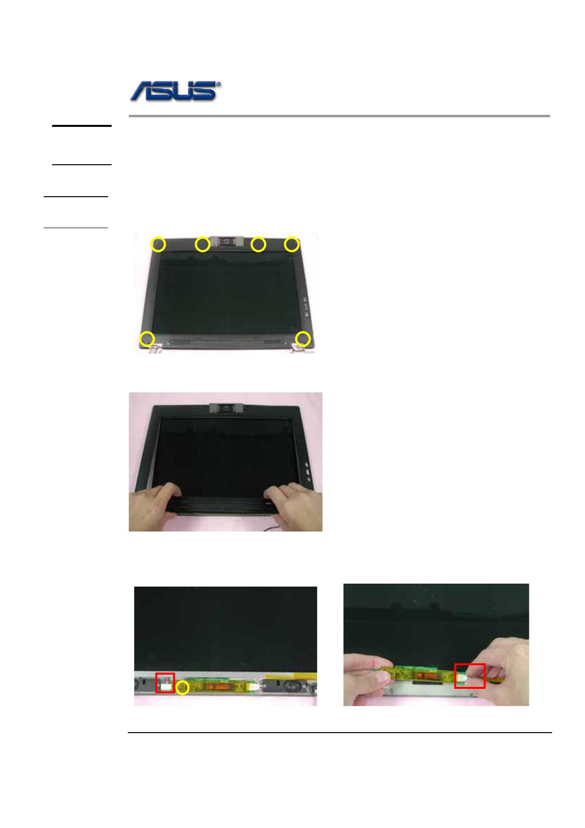
Removing LCD Module
1. Remove 6 rubber pads and 6 screws (M2.5 x 4L) from LCD module.
2. Prying the inside edges of the top front bezel, then separate it from LCD back
cover and take LCD front bezel away.
3. Disconnect the cable and remove 1 screw then take away Inverter board and
disconnect the LCD cable.
LCD
MODULE
LCD
REMOVAL
M2.5*4L
Disassembly Procedure
2 - 11
4. Remove 4 crews(M2.5*4L(K)) and take away the LCD module .
5. Remove 2 screws(M2*4L(K)) on the right LCD bracket , and 2 screws on the
ilft side to disassemble LCD brackets.
6. Remove 2 tapes and dissconnect coaxial cable then take it away.
7. Remove 4 screws(M2*4L(K)) on the right & left speaker then take away the
both speakers.
LCD
DISASSEMBLY
M2.5*4L
M2*4L
M2*4L
M2*4L
Disassembly Procedure
2 - 12
8. Remove 2 screws (M2*3L(K)) and cable.
9. Remove the speaker cable and take the Microphone board off.
10. Remove 1 screw (M2*3L(K)) and disconnect the FPC then take the CMOS
camera board off.
11. Take away the camera cover.
M2*3L
M2*3L
Disassembly Procedure
2 - 13
12. Remove 2 screws (M2*3L(K)) and disconnect the FPC then take the bracket.
10. Take away the CMOUS camera.
Motherboard module
The illustrations below show how to disassemble and remove the Motherboard
module
Removing Motherboard Module
1. Remove 1 screw (M2*3L(K)) on the Motherboard Module.
MOTHERBOARD
MODULE
MDC
MODULE
REMOVAL
M2*3L
M2*3L
Disassembly Procedure
2 - 14
2. Remove 2 screws (M2*3L(K)) and disconnect the cable then take away the
Modem board.
3. Take away the Motherboard board from the left side.
4. Remove 2 screws (M2*3L(K)) and take away ODO Jack board
M2*3L
M2*3L
Disassembly Procedure
2 - 15
5. Disconnect the ODO Jack FPC.
Wireless module
The illustrations below show how to disassemble and remove the Wireless module
Removing Wireless Module
1. Remove the Wireless LAN module by opening the 2 latches aside, and pull out the
module.
2. Remove 1 screw (M2*3L (K)) and take away the TPM board .
WIRELESS
MODULE
WIRELESS
MODULE
REMOVAL
M2*3L
  • Page 1 1
  • Page 2 2
  • Page 3 3
  • Page 4 4
  • Page 5 5
  • Page 6 6
  • Page 7 7
  • Page 8 8
  • Page 9 9
  • Page 10 10
  • Page 11 11
  • Page 12 12
  • Page 13 13
  • Page 14 14
  • Page 15 15

Asus WSF User manual

Category
Notebooks
Type
User manual
This manual is also suitable for

Asus WSF Series Notebook WSF is a versatile and powerful laptop designed to meet the demands of both personal and professional users. With its robust processing capabilities, ample memory, and dedicated graphics, it excels in handling complex tasks, multimedia editing, and gaming. The inclusion of multiple ports, including USB, HDMI, and Ethernet, ensures seamless connectivity with various peripherals and networks. Additionally, its long-lasting battery life and lightweight design make it an ideal companion for those who value portability and productivity on the go.

Ask a question and I''ll find the answer in the document

Finding information in a document is now easier with AI