Insys QLM-H101 Designer’s Guide
- Category
- Networking
- Type
- Designer’s Guide

QLM wireless
QLM-H101
Designer's Guide


Copyright © April 15 INSYS MICROELECTRONICS GmbH
Any duplication of this manual is prohibited. All rights on this documentation and
the devices are with INSYS MICROELECTRONICS GmbH Regensburg.
Trademarks
The use of a trademark not shown below is not an indication that it is freely availa-
ble for use.
MNP is a registered trademark of Microcom Inc.
IBM PC, AT, XT are registered trademarks of International Business Machine Cor-
poration.
INSYS®, VCom®, e-Mobility LSG® and e-Mobility PLC® are registered trademarks of
INSYS MICROELECTRONICS GmbH.
Windows™ is a registered trademark of Microsoft Corporation.
Linux is a registered trademark of Linus Torvalds.
Publisher:
INSYS MICROELECTRONICS GmbH
Hermann-Köhl-Str. 22
D-93049 Regensburg, Germany
Phone: +49 941 58692 0
Fax: +49 941 58692 45
E-mail: [email protected]
Internet: http://www.insys-icom.com
Date: Apr-15
Item: 31-22-04.038
Version: 1.5
Language: EN

Content
4
Apr-15
1 Preface ..................................................................................................... 7
1.1 Defects Liability Terms .......................................................................................... 7
1.2 Feedback ............................................................................................................... 7
1.3 Marking of Warnings and Notes ............................................................................ 8
1.4 Symbols and the Formatting in this Manual .......................................................... 9
2 Safety ..................................................................................................... 10
2.1 Intended Use ....................................................................................................... 10
2.2 Permissible Technical Limits ................................................................................ 11
2.3 Responsibilities of the Operator ........................................................................... 11
2.4 Qualification of the Personnel .............................................................................. 11
2.5 Instructions for Transport and Storage ................................................................ 11
2.6 Environmental Protection .................................................................................... 12
2.7 Safety Instructions for Integrating the Component .............................................. 12
2.8 General Safety Instructions .................................................................................. 12
3 Using Open Source Software ................................................................. 14
3.1 General Information ............................................................................................. 14
3.2 Special Liability Regulations ................................................................................ 15
3.3 Used Open-Source Software ............................................................................... 15
4 General Information ............................................................................... 16
5 Technical Data ....................................................................................... 17
5.1 Physical features .................................................................................................. 17
5.2 Technological Features ........................................................................................ 18
6 Connections ........................................................................................... 19
6.1 Board Layout ....................................................................................................... 19
6.2 Antenna Connectors ............................................................................................ 20
6.3 Pin Layout Terminal Strip CON1 .......................................................................... 21
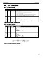
6.4 PIN Specifications ................................................................................................ 23
6.4.1 Functional Inputs .................................................................................... 23
6.4.2 Indication Signals ................................................................................... 23
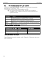
6.5 I2C Bus Connection for LED Control .................................................................... 24
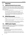
7 Design Notes ......................................................................................... 26
7.1 Application development for several variants ...................................................... 26
7.2 SIM card holder connection................................................................................. 26
7.3 CE/EMC Compliant Integration ............................................................................ 26
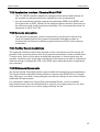
7.3.1 Your Application ..................................................................................... 26
7.3.2 Application Interface / Terminal Strip CON1 .......................................... 27
7.3.3 Antenna connection ............................................................................... 27
7.3.4 Further Recommendations ..................................................................... 27
7.3.5 Reference Documents ............................................................................ 27
8 Function Overview ................................................................................. 28
9 Commissioning ...................................................................................... 33

Contents
Apr-15 5
10 Operating Principle ................................................................................ 34
10.1 Operating the Web Interface ............................................................................... 34
10.2 Configuration via Quick Start Wizard ................................................................... 35
10.3 Access via HTTPS Protocol .................................................................................. 36
11 Functions ............................................................................................... 37
11.1 Basic Settings ...................................................................................................... 37
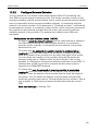
11.1.1 Configuring Web Interface Access ........................................................ 37
11.1.2 Setting IP Addresses .............................................................................. 38
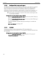
11.1.3 Entering a Static Route........................................................................... 39
11.1.4 Entering Host Names ............................................................................. 39
11.1.5 Configuring MAC Filter .......................................................................... 40
11.1.6 Configuring Access Protection via Radius Server .................................. 40
11.1.7 Configuring Command Line Interface CLI Access ................................ 41
11.2 UMTS .................................................................................................................. 42
11.2.1 Entering the PIN of the SIM Card ........................................................... 42
11.2.2 Configure Network Selection ................................................................. 43
11.2.3 Configure Daily Login and Logout ......................................................... 44
11.2.4 Terminal .................................................................................................. 44
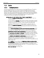
11.3 Dial-In .................................................................................................................. 45
11.3.1 Configuring Dial-In ................................................................................. 45
11.3.2 Automatic callback ................................................................................. 46
11.3.3 Routing ................................................................................................... 47
11.3.4 Creating or Deleting a Firewall Rule ....................................................... 47
11.4 Dial-Out ............................................................................................................... 49
11.4.1 Configuring Dial-Out .............................................................................. 49
11.4.2 Configuring Leased Line Operation ........................................................ 50
11.4.3 Configuring a Periodical Dial-Out Connection Setup ............................. 51
11.4.4 Routing ................................................................................................... 52
11.4.5 Setting up a Dialling Filter ...................................................................... 53
11.4.6 Creating or Deleting a Firewall Rule ....................................................... 54
11.4.7 Creating or Deleting a Port Forwarding Rule ......................................... 55
11.4.8 Defining the Exposed Host ..................................................................... 56
11.5 VPN ..................................................................................................................... 57
11.5.1 VPN General ........................................................................................... 57
11.5.2 OpenVPN General .................................................................................. 57
11.5.3 Setting Up an OpenVPN Server ............................................................. 59
11.5.4 Setting Up an OpenVPN Client .............................................................. 63
11.5.5 PPTP General .......................................................................................... 66
11.5.6 Setting Up a PPTP Server ....................................................................... 67
11.5.7 Setting Up a PPTP Client ........................................................................ 68
11.5.8 Setting Up IPsec ..................................................................................... 70
11.5.9 Configuring a GRE Tunnel ...................................................................... 74
11.6 Serial Ethernet Gateway ...................................................................................... 75
11.6.1 Setting up the Serial Ethernet Gateway ................................................. 75
11.6.2 Configuring Serial Ethernet Gateway Interface ...................................... 77
11.6.3 Modem Emulator ................................................................................... 79
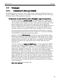
11.7 Messages ............................................................................................................ 81
11.7.1 Configuring the Message Dispatch ........................................................ 81
11.7.2 Enabling SMS Receipt ............................................................................ 82
11.7.3 Configuring E-Mail Dispatch .................................................................. 84
11.7.4 Configuring SMS Dispatch ..................................................................... 85
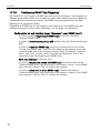
11.7.5 Configuring SNMP Trap Triggering ........................................................ 86

Content
6
Apr-15
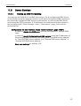
11.8 Server Services .................................................................................................... 87
11.8.1 Setting up DNS Forwarding ................................................................... 87
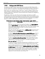
11.8.2 Dynamic DNS Update ............................................................................ 88
11.8.3 Setting up the DHCP Server ................................................................... 89
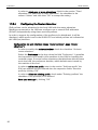
11.8.4 Configuring the Router Advertiser ......................................................... 90
11.8.5 Configuring a Proxy Server .................................................................... 91
11.8.6 Configuring an URL Filter ....................................................................... 92
11.8.7 Configuring IPT....................................................................................... 92
11.8.8 Configuring the SNMP Agent ................................................................ 94
11.8.9 Configuring MCIP ................................................................................... 95
11.9 System Configuration .......................................................................................... 96
11.9.1 Displaying the System Log .................................................................... 96
11.9.2 Displaying the Last System Messages ................................................... 96
11.9.3 Setting Time and Time Zone .................................................................. 97
11.9.4 Reset ...................................................................................................... 98
11.9.5 Update .................................................................................................... 99
11.9.6 Updating the Firmware ........................................................................ 100
11.9.7 Uploading the Configuration File ......................................................... 102
11.9.8 Download ............................................................................................. 103
11.9.9 Sandbox ............................................................................................... 104
11.9.10 Debugging ............................................................................................ 106
11.10 GPS.................................................................................................................... 107
12 Maintenance, Repair and Troubleshooting ........................................... 108
12.1 Maintenance ...................................................................................................... 108
12.2 Troubleshooting ................................................................................................. 108
12.3 Repair ................................................................................................................ 108
13 Waste Disposal .................................................................................... 109
13.1 Repurchasing of Legacy Systems ...................................................................... 109
14 Declaration of Conformity .................................................................... 110
15 Export Restriction ................................................................................ 111
16 Licenses ............................................................................................... 112
16.1 GNU GENERAL PUBLIC LICENSE ..................................................................... 112
16.2 GNU LIBRARY GENERAL PUBLIC LICENSE ...................................................... 115
16.3 Other Licenses ................................................................................................... 120
17 International Safety Instructions .......................................................... 123
17.1 Safety Precautions ............................................................................................. 123
18 Glossary ............................................................................................... 125
19 Tables and Diagrams............................................................................ 128
19.1 List of Tables ..................................................................................................... 128
19.2 List of Diagrams ................................................................................................ 128
20 Index .................................................................................................... 129

QLM wireless
Preface
7
1 Preface
This manual allows for the safe and efficient use of the product. The manual is part
of the product and must always be stored accessible for installation, commission-
ing and operating personnel.
1.1 Defects Liability Terms
A usage not according to the intended purpose, an ignorance of this documenta-
tion, the use of insufficiently qualified personnel as well as unauthorised modifica-
tions exclude the liability of the manufacturer for damages resulting from this. The
liability of the manufacturer ceases to exist.
The regulations of our Delivery and Purchasing Conditions are effective. These can
be found on our website (www.insys-icom.de/imprint/) under “General Terms and
Conditions“.
1.2 Feedback
We are permanently improving our products and the associated technical docu-
mentation. Your feedback is very helpful for this. Please tell us what you like in par-
ticular on our products and publications and what can be improved from your point
of view. We highly appreciate your suggestions and will include them in our work
to support you and all our customers. We are looking forward to any of your feed-
back.
Please send an e-mail to [email protected].
We'd like to know your applications. Please send us a few headwords that we
know the applications you solve using products of INSYS icom.

Preface
QLM wireless
8
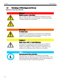
1.3 Marking of Warnings and Notes
Symbols and Key Words
Danger!
Risk of severe or fatal injury
One of these symbols in conjunction with the key word
Danger indicates an imminent danger. It will cause death
or severe injuries if not avoided.
Warning!
Personal injury
This symbol in conjunction with the key word Warning
indicates a possibly hazardous situation. It might cause
death or severe injuries if not avoided.
Caution!
Slight injury and / or material damage
This symbol in conjunction with the key word Caution
indicates a possibly hazardous or harmful situation. It
might cause slight or minor injuries or a damage of the
product or something in its vicinity if not avoided.
Note
Improvement of the application
This symbol in conjunction with the key word Note
indicates hints for the user or very useful information. This
information helps with installation, set-up and operation of
the product to ensure a fault-free operation.

QLM wireless
Preface
9
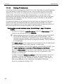
1.4 Symbols and the Formatting in this Manual
This section describes the definition, formatting and symbols used in this manual.
The various symbols are meant to help you read and find the information relevant
to you. The following text is structured like a typical operating instruction of this
manual.
Bold print: This will tell you what the following steps will result in
After that, there will be a detailed explanation why you could perform the
following steps to be able to reach the objective indicated first. You can
decide whether the section is relevant for you or not.
An arrow will indicate prerequisites which must be fulfilled to be able to
process the subsequent steps in a meaningful way. You will also learn
which software or which equipment you will need.
1. One individual action step: This tells you what you need to do at this
point. The steps are numbered for better orientation.
A result which you will receive after performing a step will be marked
with a check mark. At this point, you can check if the previous steps
were successful.
Additional information which you should consider are marked with a
circled "i". At this point, we will indicate possible error sources and tell
you how to avoid them.
Alternative results and steps are marked with an arrow. This will tell
you how to reach the same results performing different steps, or what
you could do if you didn't reach the expected results at this point.

Safety
QLM wireless
10
2 Safety
The Safety section provides an overview about the safety instructions, which must
be observed for the operation of the product.
The product is constructed according to the currently valid state-of-the-art technol-
ogy and reliable in operation. It has been checked and left the factory in flawless
condition concerning safety. In order to maintain this condition during the service
life, the instructions of the valid publications and certificates must be observed and
followed.
It is necessary to adhere to the general safety instructions must when operating the
product. The descriptions of processes and operation procedures are provided with
precise safety instructions in the respective sections in addition to the general
safety instructions.
Moreover, the local accident prevention regulations and general safety regulations
for the operating conditions of the device are effective.
An optimum protection of the personnel and the environment from hazards as well
as a safe and fault-free operation of the product is only possible if all safety instruc-
tions are observed.
2.1 Intended Use
The product may only be used for the purposes specified in the function overview.
In addition, it may be used for the following purposes:
Usage and mounting in an explicitly designed device.
The product may not be used for the following purposes and used or operated un-
der the following conditions:
Usage, controlling, switching and data transmission of machines and
systems, which are operated in explosive atmospheres.
Controlling, switching and data transmission of machines, which may
involve risks to life and limb due to their functions or when a
breakdown occurs.

QLM wireless
Safety
11
2.2 Permissible Technical Limits
The product is only intended for the use within the permissible technical limits
specified in the data sheets.
The following permissible limits must be observed:
The ambient temperature limits must not be fallen below or
exceeded.
The supply voltage range must not be fallen below or exceeded.
The maximum humidity must not be exceeded and condensate
formation must be prevented.
The maximum switching voltage and the maximum switching current
load must not be exceeded.
The maximum input voltage and the maximum input current must not
be exceeded.
2.3 Responsibilities of the Operator
As a matter of principle, the operator must observe the legal regulations, which are
valid in his country, concerning operation, functional test, repair and maintenance
of electrical devices.
2.4 Qualification of the Personnel
The installation, commissioning and maintenance of the product must only be per-
formed by trained expert personnel, which has been authorised by the plant opera-
tor. The expert personnel must have read and understood this documentation and
observe the instructions.
Electrical connection and commissioning must only be performed by a person, who
is able to work on electrical installations and identify and avoid possible hazards in-
dependently, based on professional training, knowledge and experience as well as
knowledge of the relevant standards and regulations.
2.5 Instructions for Transport and Storage
The following instructions must be observed:
Do not expose the product to moisture and other potential hazardous
environmental conditions (radiation, gases, etc.) during transport and
storage. Pack product accordingly.
Pack product sufficiently to protect it against shocks during transport
and storage, e.g. using air-cushioned packing material.
Check product for possible damages, which might have been caused by improper
transport, before installation. Transport damages must be noted down to the ship-
ping documents. All claims or damages must be filed immediately and before in-
stallation against the carrier or party responsible for the storage.

Safety
QLM wireless
12
2.6 Environmental Protection
Dispose the product and the packaging according to the relevant environmental
protection regulations. The Waste Disposal section in this manual contains notes
about disposing the product. Separate the packaging components of cardboard
and paper as well as plastic and deliver them to the respective collection systems
for recycling.
2.7 Safety Instructions for Integrating the Component
The integration of the component must only be made by authorised expert person-
nel according to the wiring diagrams.
Observe the general safety precautions when handling electrostatic-discharge-sen-
sitive parts to prevent a damage of the component.
2.8 General Safety Instructions
Caution!
Electrostatic discharges may damage the product!
Damage of the product.
Observe the general safety precautions when handling
electrostatic-discharge-sensitive parts.
Caution!
Overvoltage by exceeding the permissible voltage range
and voltage peaks!
Fire hazard and damage of the product.
Ensure a supply of the product within the permissible
voltage range.
Caution!
Distance from antennas to persons!
A too low distance from cellular antennas to persons can
affect the health.
Please observe to keep a minimum distance of 20 cm
between the cellular antenna and persons during
operation.

QLM wireless
Safety
13
Note
Export restriction for FCC!
Possible offence against approval regulations.
If the final product is not approved in the U.S. territories,
the application manufacturer shall take care that the
850 MHz and 1900 MHz frequency bands be deactivated
and that band settings be inaccessible to end users. If
these demands are not met (e.g. if the AT interface is
accessible to end users), it is the responsibility of the
application manufacturer to always ensure that the
application be not exported to countries within the area of
validity of the FCC.
Important note for installations in Sweden or Norway:
Utrustning som är kopplad till skyddsjord via jordat vägguttag och/eller
via annan utrustning och samtidigt är kopplad till kabel-TV nät kan I
visa fall medföra risk fr brand. För att undvika detta skall vid anslutning
av utrustningen till kabel-TV nät galvanisk isolator finnas mellan
utrustningen och kabel-TV nätet.

Using Open Source Software
QLM wireless
14
3 Using Open Source Software
3.1 General Information
Our product QLM-H101 contains, amongst others, so-called open-source software
that is provided by third parties and has been published for free public use. The
open-source software is subject to special open-source software licenses and the
copyright of third parties. Basically, each customer can use the open-source soft-
ware freely in compliance with the licensing terms of the respective producers. The
rights of the customer to use the open-source software beyond the purpose of our
product are regulated in detail by the respective concerned open-source software
licenses. The customer use the open-source software freely, as provided in the re-
spective effective license, beyond the purpose that the open-source software gets
in our product. In case there is a contradiction between the licensing terms for our
product and the respective open-source software license, the respective relevant
open-source software license takes priority over our licensing terms, as far as the
respective open-source software is concerned by this.
The use of the used open-source software is possible free of charge. We do not de-
mand usage fees or any comparable fees for the use of the open-source software
contained in our product. The use of the open-source software in our product by
the customer is not part of the earnings we achieve with the contractual compen-
sation.
All open-source software programs contained in our product can be taken from the
available list. The most important open-source software licenses are listed in the Li-
censes section at the end of this publication.
As far as programs contained in our product are subject to the GNU General Public
License (GPL), GNU Lesser General Public License (LGPL), Clarified Artistic License
or another open-source software license, which regulates that the source code
must be made available, and if this software is not already delivered in source code
on a data carrier with our product, we will send you this at any time upon request.
If it is required to send this on a data carrier, the sending will be made against pay-
ment of a cost compensation of € 10,00. Our offer to send the source code upon
request ceases automatically 3 years after delivery of our product to the customer.
Requests must be directed to the following address, if possible under specification
of the serial number:
INSYS MICROELECTRONICS GmbH
Hermann-Köhl-Str. 22
93049 Regensburg, Germany
Phone +49 941 58692 0
Fax +49 941 58692 45
E-mail: [email protected]

QLM wireless
Using Open Source Software
15
3.2 Special Liability Regulations
We do not assume any warranty or liability, if the open-source software programs
contained in our product are used by the customer in a manner that does not com-
ply any more with the purpose of the contract, which is the basis of the acquisition
of our product. This concerns in particular any use of the open-source software
programs outside of our product. The warranty and liability regulations that are pro-
vided by the respective effective open-source software license for the respective
open-source software as listed in the following are effective for the use of the
open-source software beyond the purpose of the contract. In particular, we are not
liable, if the open-source software in our product or the complete software configu-
ration in our product is changed. The warranty granted with the contract, which is
the basis of the acquisition of our product, is only effective for the unchanged
open-source software and the unchanged software configuration in our product.
3.3 Used Open-Source Software
Please contact our support department ([email protected]) for a list of the
open-source software used in this product.

General Information
QLM wireless
16
4 General Information
The QLM-H101 is designed to provide a flexible and pre-tested embedded module,
which can be used as add-on board to any processor based design to connect an
application to a network using a cellular network.
A carrier board is available for the module as reference environment. The carrier
board includes SIM card holder, power supply, external connectors and protection
circuitry.
For information about this, refer to http://www.insys-icom.de/demoboard.

QLM wireless
Technical Data
17
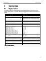
5 Technical Data
5.1 Physical features
All specified data was measured with nominal input voltage, at full load, and an
ambient temperature of 25 ℃. The limit value tolerances are subject to the usual var-
iations.
Physical Feature
Value
Operation voltage VCC
+3.3 V (±5%) DC
Power consumption
Offline mode approx. 1 W (engine off)
Online mode max. 4.5 W (worst case)
Input level "High" (VIH)
>2.0 V, ≤VCC
Input level "Low" (VIL)
<0.8 V, >0 V
Output level "High" (VOH)
>2.4 V (IOH <2 mA)
Output level "Low" (VOL)
<0.4 V (IOL <2 mA)
Transmitted output:
UMTS 850: Class 3
UMTS 1900: Class 3
UMTS 2100: Class 3
EGSM 850 and 900: Class 4
GSM 1800 and 1900: Class 1
EGSM 850 and 900: Class E2
GSM 1800 and 1900: Class E2
0.25 W
0.25 W
0.25 W
2 W
1 W
0.5 W
0.5 W
GPS time to first fix (TTFF) cold:
warm:
25 … 32 s
10 … 29 s
Weight
30 g
Dimensions (Length x Width x Height)
56.4 mm x 56.4 mm x 12.5 mm
PCB thickness
1.6 mm
Temperature range
-30 °C … 65 °C
Maximum permissible humidity
95%, non-condensing
Table 1: Physical Features

Technical Data
QLM wireless
18
5.2 Technological Features
Technological Feature
Value
GSM/GPRS frequencies (2G)
850, 900, 1800, 1900 MHz
UMTS/HSPA frequencies (3G)
800, 850, 900, 1900, 2100 MHz
SIM card
Mini-SIM
SMS
SMS dispatch; incoming SMS can be
received, but cannot be accessed via the web
interface.
CSD
up to 14,4 kBit/s with subsequent PPP
connection
GPRS
GPRS Multislot Class 12, Coding scheme 1 to
4, PBCCH, Mobile Station Class B
EDGE (EGPRS)
EDGE Multislot Class 12, Modulation and
Coding Scheme MCS 1-9
UMTS
Uplink up to 384 kBit/s / downlink up to 384
kBit/s
HSUPA (uplink) up to 5.7 MBit/s
HSDPA (downlink) up to 14.4 MBit/s
Application interfaces
Ethernet (10/100 BaseT, connection to
Ethernet transmitter)
RS232 (3.3 V CMOS)
Table 2: Technological Features

QLM wireless
Connections
19
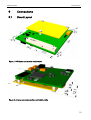
6 Connections
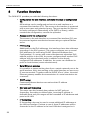
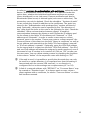
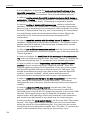
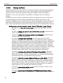
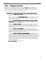
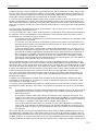
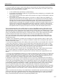
6.1 Board Layout
Figure 1: PCB layout and terminal strip location
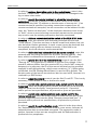
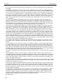
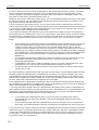
Figure 2: Antenna connector position and height profile

Connections
QLM wireless
20
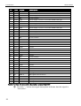
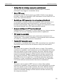
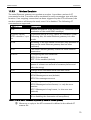
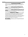
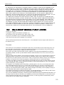
Item
Type
Description
CON1
FCI, type 61083-081602-
LF
Connection for external memory, LED outputs, Ethernet
interface, RS232 interface, I2C bus, power supply, SIM card
holder, reset input
Table 3: Specification and assignment of the terminal strips
The FCI types 61082-081602-LF (5 mm board distance), 61082-
082602-LF (9 mm board distance) or 61082-083602-LF (13 mm board
distance) can be used as counter connector for CON1. The respective
data sheets can be found under www.fciconnect.com (search for
"61083-081602").
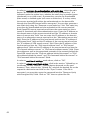
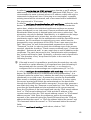
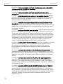
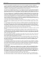
Please note that our pin definitions shown here are decisive. It is
possible that the pin definitions of the connector manufacturers are
different.
Figure 3: Pin definitions of CON1
6.2 Antenna Connectors
The antenna connections are performed via RF connectors (Hirose U.FL series). The
antenna connectors are on the cellular engine board. To connect, position the an-
tenna plug above the antenna connector and snap-in the plug by pushing on it's
top through the cut-out in the PCB using a suitable object (e.g. metal rod or torx
screwdriver).
Adapter cables from FME to connect standard cellular antennas are available from
INSYS.
Item
Type
Description
A
U.FL
Cellular antenna connector
B
U.FL
Cellular diversity antenna connector
C
U.FL
GPS antenna connector
Table 4: Specification and assignment of the antenna connections
Page is loading ...
Page is loading ...
Page is loading ...
Page is loading ...
Page is loading ...
Page is loading ...
Page is loading ...
Page is loading ...
Page is loading ...
Page is loading ...
Page is loading ...
Page is loading ...
Page is loading ...
Page is loading ...
Page is loading ...
Page is loading ...
Page is loading ...
Page is loading ...
Page is loading ...
Page is loading ...
Page is loading ...
Page is loading ...
Page is loading ...
Page is loading ...
Page is loading ...
Page is loading ...
Page is loading ...
Page is loading ...
Page is loading ...
Page is loading ...
Page is loading ...
Page is loading ...
Page is loading ...
Page is loading ...
Page is loading ...
Page is loading ...
Page is loading ...
Page is loading ...
Page is loading ...
Page is loading ...
Page is loading ...
Page is loading ...
Page is loading ...
Page is loading ...
Page is loading ...
Page is loading ...
Page is loading ...
Page is loading ...
Page is loading ...
Page is loading ...
Page is loading ...
Page is loading ...
Page is loading ...
Page is loading ...
Page is loading ...
Page is loading ...
Page is loading ...
Page is loading ...
Page is loading ...
Page is loading ...
Page is loading ...
Page is loading ...
Page is loading ...
Page is loading ...
Page is loading ...
Page is loading ...
Page is loading ...
Page is loading ...
Page is loading ...
Page is loading ...
Page is loading ...
Page is loading ...
Page is loading ...
Page is loading ...
Page is loading ...
Page is loading ...
Page is loading ...
Page is loading ...
Page is loading ...
Page is loading ...
Page is loading ...
Page is loading ...
Page is loading ...
Page is loading ...
Page is loading ...
Page is loading ...
Page is loading ...
Page is loading ...
Page is loading ...
Page is loading ...
Page is loading ...
Page is loading ...
Page is loading ...
Page is loading ...
Page is loading ...
Page is loading ...
Page is loading ...
Page is loading ...
Page is loading ...
Page is loading ...
Page is loading ...
Page is loading ...
Page is loading ...
Page is loading ...
Page is loading ...
Page is loading ...
Page is loading ...
Page is loading ...
Page is loading ...
Page is loading ...
Page is loading ...
Page is loading ...
Page is loading ...
-
 1
1
-
 2
2
-
 3
3
-
 4
4
-
 5
5
-
 6
6
-
 7
7
-
 8
8
-
 9
9
-
 10
10
-
 11
11
-
 12
12
-
 13
13
-
 14
14
-
 15
15
-
 16
16
-
 17
17
-
 18
18
-
 19
19
-
 20
20
-
 21
21
-
 22
22
-
 23
23
-
 24
24
-
 25
25
-
 26
26
-
 27
27
-
 28
28
-
 29
29
-
 30
30
-
 31
31
-
 32
32
-
 33
33
-
 34
34
-
 35
35
-
 36
36
-
 37
37
-
 38
38
-
 39
39
-
 40
40
-
 41
41
-
 42
42
-
 43
43
-
 44
44
-
 45
45
-
 46
46
-
 47
47
-
 48
48
-
 49
49
-
 50
50
-
 51
51
-
 52
52
-
 53
53
-
 54
54
-
 55
55
-
 56
56
-
 57
57
-
 58
58
-
 59
59
-
 60
60
-
 61
61
-
 62
62
-
 63
63
-
 64
64
-
 65
65
-
 66
66
-
 67
67
-
 68
68
-
 69
69
-
 70
70
-
 71
71
-
 72
72
-
 73
73
-
 74
74
-
 75
75
-
 76
76
-
 77
77
-
 78
78
-
 79
79
-
 80
80
-
 81
81
-
 82
82
-
 83
83
-
 84
84
-
 85
85
-
 86
86
-
 87
87
-
 88
88
-
 89
89
-
 90
90
-
 91
91
-
 92
92
-
 93
93
-
 94
94
-
 95
95
-
 96
96
-
 97
97
-
 98
98
-
 99
99
-
 100
100
-
 101
101
-
 102
102
-
 103
103
-
 104
104
-
 105
105
-
 106
106
-
 107
107
-
 108
108
-
 109
109
-
 110
110
-
 111
111
-
 112
112
-
 113
113
-
 114
114
-
 115
115
-
 116
116
-
 117
117
-
 118
118
-
 119
119
-
 120
120
-
 121
121
-
 122
122
-
 123
123
-
 124
124
-
 125
125
-
 126
126
-
 127
127
-
 128
128
-
 129
129
-
 130
130
-
 131
131
-
 132
132
-
 133
133


Insys QLM-H101 Designer’s Guide
- Category
- Networking
- Type
- Designer’s Guide
Ask a question and I''ll find the answer in the document
Finding information in a document is now easier with AI
Related papers
-
Insys QLM-W100 Designer’s Guide
-
-
Insys icom Data Suite Quick Installation Guide
-
-
-
-
-
-
-
