Page is loading ...

77-1632-R19 (6/2020) 1 / 4 www.carlisleft.com
Replacement
Part No. Description
Ind.
Parts
Req'd.
20-3699 lSoc. HD. Cap Screw, 10-24 x 1"Long 6
20-4456 lock Nut (84-408) 1
33-190 Pin 1
72-337 Swivel Nut 1
73-50 D.M. Nipple 1
83-1290 Gauge, 0-150 Psi (84-412) 1
83-1355 Gauge, 0-100 Psi (84-345, 84-408) 1
84-40 Connector 1
84-317 Spring (84-345) 1
84-321 Bonnet 1
84-322 Screw 1
84-323 Washer 1
84-324 Stem 1
84-325 Stem Assembly 1
84-326 Follower 1
84-328 Disc 2
84-330 Diaphragm 1
84-331 Nut 1
84-334 *Seat 1
Replacement
Part No. Description
Ind.
Parts
Req'd.
84-335 *Valve 1
84-318 Tailpiece 1
84-340 Key 1
84-327 Retainer 1
84-344 Body 1
84-337 Inlet 1
84-354 Socket 1
84-355 Cap 1
84-388 Gasket 1
84-395 Rod 1
84-399 Diaphragm (PTFE) 1
84-452 Spring (84-412) 1
84-460 Body (84-408 only) 1
84-463 Gasket 1
lBeforeinstallingtheRegulator,tightenall(6)angescrewssecurely.
Also furnished in Repair Kit 6-221. Please order Kit separately.
* Available only as a matched set. Please specify 84-481.
DETAIL “A”
REGULATED
F
LUID OUTLET
SE
E DETAIL
“A”
84-399 DIAPHRAGM
84-463 GASKET
84-317 (84-345)
84-452 (84-412)
84-388 GASKET
84-324 STEM
84-326 FOLLOWER
84-323 WA
S
HER
33-190 PIN
84-322 SCREW
84-340 KEY
84-321
BONNET
84-354 S
O
CKET
73-50 NIPPLE
84-395 ROD
84-40 CONNECTOR
84-344 BODY
84-327 RETAINER
84-335 VA LVE*
84-337 INLET
84-355 CAP
84-318 TAILPIECE
72-337 SWIVEL NUT
84-334 SEAT*
84-325 STEM
AS
S
EMBLY
SPRING
UNRE
GULATED
FLUID INLET
83-1290
(84-412)
83-1355
(84-345)
GA UG E
84-330 DIA PHRA GM
84-331 NUT
84-328 DISC
20-3699 SCREW
TORQUE TO 35–45 IN-LBS
TORQUE TO 120–150 IN-LBS
FLUID REGULATORS
MODELS 84-345 (5-55 PSI) AND 84-412 (5-100 PSI)
KEY OPERATED
EN
SERVICE MANUAL
Use of PTFE tape on all
tapered threads is permittable.

EN
77-1632-R19 (6/2020)2 / 4www.carlisleft.com
LOCK OUT / TAG-OUT
Failure to de-energize, disconnect, lock out and tag-out all power
sources before performing equipment maintenance could cause
serious injury or death.
OPERATOR TRAINING
All personnel must be trained before operating finishing
equipment.
EQUIPMENT MISUSE HAZARD
Equipment misuse can cause the equipment to rupture,
malfunction, or start unexpectedly and result in serious injury.
PROJECTILE HAZARD
You may be injured by venting liquids or gases that are released
under pressure, or flying debris.
PINCH POINT HAZARD
Moving parts can crush and cut. Pinch points are basically any
areas where there are moving parts.
INSPECT THE EQUIPMENT DAILY
Inspect the equipment for worn or broken parts on a daily basis.
Do not operate the equipment if you are uncertain about its
condition.
In this part sheet, the words WARNING, CAUTION and NOTE are used to
emphasize important safety information as follows:
Hazards or unsafe practices which
could result in minor personal injury,
product or property damage.
!
CAUTION
Hazards or unsafe practices which
could result in severe personal
injury, death or substantial property
damage.
!
WARNING
Important installation, operation or
maintenance information.
NOTE
Read the following warnings before using this equipment.
READ THE MANUAL
Before operating finishing equipment, read and understand all
safety, operation and maintenance information provided in the
operation manual.
WEAR SAFETY GLASSES
Failure to wear safety glasses with side shields could result in
serious eye injury or blindness.
NEVER MODIFY THE EQUIPMENT
Do not modify the equipment unless the manufacturer provides
written approval.
IT IS THE RESPONSIBILITY OF THE EMPLOYER TO PROVIDE THIS INFORMATION TO THE OPERATOR OF THE EQUIPMENT.
FOR FURTHER SAFETY INFORMATION REGARDING THIS EQUIPMENT, SEE THE GENERAL EQUIPMENT SAFETY BOOKLET (77-5300).
KNOW WHERE AND HOW TO SHUT OFF THE EQUIPMENT
IN CASE OF AN EMERGENCY
PRESSURE RELIEF PROCEDURE
Always follow the pressure relief procedure in the equipment
instruction manual.
NOISE HAZARD
You may be injured by loud noise. Hearing protection may be
required when using this equipment.
STATIC CHARGE
Fluid may develop a static charge that must be dissipated through
proper grounding of the equipment, objects to be sprayed and all
other electrically conductive objects in the dispensing area. Improper
grounding or sparks can cause a hazardous condition and result in
fire, explosion or electric shock and other serious injury.
WEAR RESPIRATOR
Toxic fumes can cause serious injury or death if inhaled.
Wear a respirator as recommended by the fluid and solvent
manufacturer’s Safety Data Sheet.
TOXIC FLUID & FUMES
Hazardous fluid or toxic fumes can cause serious injury or death if
splashed in the eyes or on the skin, inhaled, injected or
swallowed. LEARN and KNOW the specific hazards or the fluids
you are using.
KEEP EQUIPMENT GUARDS IN PLACE
Do not operate the equipment if the safety devices have been
removed.
!
WARNING
AUTOMATIC EQUIPMENT
Automatic equipment may start suddenly without warning.
FIRE AND EXPLOSION HAZARD
Improper equipment grounding, poor ventilation, open flame or
sparks can cause a hazardous condition and result in fire or
explosion and serious injury.
MEDICAL ALERT
Any injury caused by high pressure liquid can be serious. If you
are injured or even suspect an injury:
• Go to an emergency room immediately.
• Tell the doctor you suspect an injection injury.
• Show the doctor this medical information or the medical alert
card provided with your airless spray equipment.
• Tell the doctor what kind of fluid you were spraying or
dispensing.
GET IMMEDIATE MEDICAL ATTENTION
To prevent contact with the fluid, please note the following:
• Never point the gun/valve at anyone or any part of the body.
• Never put hand or fingers over the spray tip.
• Never attempt to stop or deflect fluid leaks with your hand,
body, glove or rag.
• Always have the tip guard on the spray gun before spraying.
• Always ensure that the gun trigger safety operates before
spraying.

EN
77-1632-R19 (6/2020) 3 / 4 www.carlisleft.com
MOUNTING
Regulator (3/8" N.P.T.(M) Inlet) may be mounted in either a horizontal
or vertical position. However, in all cases: to operate properly, Gauge
Riser Tube must be in a vertical position.
REGULATION
Remote Control – Connect a self-relieving type Air Regulator with
Air Hose or tubing to the Air Inlet on the Fluid Regulator. Adjust Fluid
Regulator to desired setting by operating Air Regulator and observing
Gauge reading on Fluid or Air Regulator.
Fluid should be flowing through regulator when regulating
pressure.
NOTE
BLOW-BACK
Key Operated – Use hexagon end of key. Turn counter-clockwise
and Gauge will read Inlet (main line) pressure.
Remote Control – Increase pressure with self-relieving type Air
Regulator (see “REGULATION”) until fluid regulator reaches main line
pressure. To discontinue blow-back, reset Fluid Regulator to desired
pressure as described under “REGULATION”.
When blowing back to reverse-flush Regulator, be sure air
pressure does not exceed maximum rating of Gauge.
!
CAUTION
Buzzing: When regulated pressure climbs, it normally indicates dirt
on the Seat; trigger Gun rapidly to flush Seat. If climbing continues,
open Regulator to main line to flush. If climbing still persists, replace
Valve and Seat.
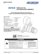
BINKS FLUID REGULATORS
Models 84-345 (5-55 psi) and 84-412 (5-100 psi), Key Operated; Model 84-408 (5-55 psi), Remote Control
INSTALLATION DATA
Installation is simplified by the use of a swivel nut inlet
connection (see photo). This is standard on all models; it
eliminates the cost of a union, and provides a quick and
convenient method to easily remove the unit from the line.
Regulation Range 5 - 55 PSI
5 - 100 PSI
3.8 Kg/CM2
7.0 Kg/CM2
Max. Rec. Flow 128 Oz./Min. 3.78 L/Min.
Max. Inlet Pressure 200 PSI 14.1 Kg/CM2
Due to variations in diaphragm stretch, fluid flow may not
shut-off when the pressure is backed off to zero. Install an
inlet valve if complete shut-off is required.
NOTE
OPERATING INSTRUCTIONS SERVICE INSTRUCTIONS
TO REPLACE FLUID VALVE & SEAT
Remove Regulator from line by loosening the Swivel Nut, always blow
back Regulator before removing. At Inlet, remove (counter-clockwise
rotation) slotted Cap Nut with screw driver; Ball Valve will slide off
Rod. Unscrew (counter-clockwise rotation) hexagon Inlet Retainer;
Valve Seat will be removed with Retainer.
Remove Valve Seat from Retainer and replace if worn. Ball Valve may
be reversed and reused unless both sides are worn.
To Reassemble – Insert Valve Seat into Retainer; note position of
Shoulder. Place Ball Valve on Rod, and screw Cap Nut on Rod and
tighten. Screw Hex Retainer on to Body and tighten. Regulator
requires no adjustments.
TO REPLACE DIAPHRAGM
Remove Regulator from line. At Inlet, remove slotted Cap Nut with
screw driver; Ball Valve will slide off Rod. Remove Bonnet by loosening
(6) Socket Head Cap Screws. Clamp Diaphragm assembly in vise,
loosen 84-331 Nut and remove Diaphragm.
To Reassemble – Reverse above procedure.
UNION
CONNECTION
M ODELS WITH
REM OTE
CONTROL AIR
INLET 1/8 NPT(F)
CONNECT TO
SELF-RELIEVING
TYPE A IR
REGULATOR
3/8 NPT INLET
3/8 NPS
OUTLET
2 1/2
10 3/8
3 1/2
2 11/16
3 3/8
6
84-335 VA LVE*
84-355 CA P NUT
84-334 SEAT*
84-395 ROD
84-327 RETA INER
BODY
*Available only as a matched
set. Please specify 84-481.

EN
77-1632-R19 (6/2020)4 / 4www.carlisleft.com
WARRANTY POLICY
This product is covered by Carlisle Fluid Technologies’ materials and workmanship limited warranty.
The use of any parts or accessories, from a source other than Carlisle Fluid Technologies,
will void all warranties. Failure to reasonably follow any maintenance guidance provided
may invalidate any warranty.
ForspecicwarrantyinformationpleasecontactCarlisleFluidTechnologies.
For technical assistance or to locate an authorized distributor,
contact one of our international sales and customer support locations.
Region Industrial/Automotive Automotive Renishing
Americas Tel: 1-800-992-4657 Tel: 1-800-445-3988
Fax: 1-888-246-5732 Fax: 1-800-445-6643
Europe, Africa,
Middle East, India
Tel: +44 (0)1202 571 111
Fax: +44 (0)1202 573 488
China Tel: +8621-3373 0108
Fax: +8621-3373 0308
Japan Tel: +81 45 785 6421
Fax: +81 45 785 6517
Australia Tel: +61 (0) 2 8525 7555
Fax: +61 (0) 2 8525 7575
CarlisleFluidTechnologiesisagloballeaderininnovativenishingtechnologies.
CarlisleFluidTechnologiesreservestherighttomodifyequipmentspecicationswithoutpriornotice.
DeVilbiss®, Ransburg®, ms®, BGK®, and Binks®
are registered trademarks of Carlisle Fluid Technologies, Inc.
©2020 Carlisle Fluid Technologies, Inc.
All rights reserved.
For the latest information about our products, visit www.carlisleft.com
/