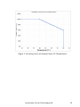
ICT DIN Series Power Supply
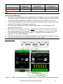
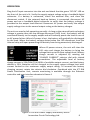
The ICT DIN Series Power Supply is a versatile and reliable power solution for a wide range of applications. With its wide-ranging AC input, dedicated battery charging port, adjustable charge current, and Form C alarm contacts, the ICT DIN Power Supply is well-suited for use in critical systems, such as telecommunications, security, and industrial automation.
The ICT DIN Power Supply can provide up to 360 watts of 48- or 24-volt DC output, making it ideal for powering a variety of devices, including routers, switches, cameras, and sensors. The power supply's wide-ranging AC input (90-264VAC) allows it to be used in a variety of countries and regions, and its low-noise emissions make it suitable for use in sensitive environments.
ICT DIN Series Power Supply
The ICT DIN Series Power Supply is a versatile and reliable power solution for a wide range of applications. With its wide-ranging AC input, dedicated battery charging port, adjustable charge current, and Form C alarm contacts, the ICT DIN Power Supply is well-suited for use in critical systems, such as telecommunications, security, and industrial automation.
The ICT DIN Power Supply can provide up to 360 watts of 48- or 24-volt DC output, making it ideal for powering a variety of devices, including routers, switches, cameras, and sensors. The power supply's wide-ranging AC input (90-264VAC) allows it to be used in a variety of countries and regions, and its low-noise emissions make it suitable for use in sensitive environments.


-
 1
1
-
 2
2
-
 3
3
-
 4
4
-
 5
5
-
 6
6
-
 7
7
-
 8
8
-
 9
9
-
 10
10
-
 11
11
-
 12
12
-
 13
13
-
 14
14


ICT DIN Series Power Supply
The ICT DIN Series Power Supply is a versatile and reliable power solution for a wide range of applications. With its wide-ranging AC input, dedicated battery charging port, adjustable charge current, and Form C alarm contacts, the ICT DIN Power Supply is well-suited for use in critical systems, such as telecommunications, security, and industrial automation.
The ICT DIN Power Supply can provide up to 360 watts of 48- or 24-volt DC output, making it ideal for powering a variety of devices, including routers, switches, cameras, and sensors. The power supply's wide-ranging AC input (90-264VAC) allows it to be used in a variety of countries and regions, and its low-noise emissions make it suitable for use in sensitive environments.
Ask a question and I''ll find the answer in the document
Finding information in a document is now easier with AI
Related papers
-
ICT Backup Series Owner's manual
-
-
-
-
-
-
-
-
-
Other documents
-
LC-Power Gaming 714W GACRUX User manual
-
LC-Power Gaming 714W Owner's manual
-
Huawei Building a Fully Connected Intelligent World User manual
-
Thinklogical ICT Integrated Client Transmitter User manual
-
 INVISIBLE FENCE ICT 801 Installation guide
-
Tannoy CMS 50T User manual
-
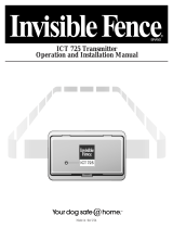 INVISIBLE FENCE ICT 725 Operation and Installation Manual
-
Airwell GCD 036 User manual
-
 TOA Electronics I6 AW ICT User manual
-
Airwell 36 User manual


