Page is loading ...

SAFETY AT WORK
VAA-2E2A-G12-SAJ/EA2L
Original Instructions
Version 1.0
FACTORY AUTOMATION
MANUAL

With regard to the supply of products, the current issue of the following document is ap-
plicable: The General Terms of Delivery for Products and Services of the Electrical Indus-
try, published by the Central Association of the Electrical Industry (Zentralverband
Elektrotechnik und Elektroindustrie (ZVEI) e.V.) in its most recent version as well as the
supplementary clause: "Expanded reservation of proprietorship"
VAA-2E2A-G12-SAJ/EA2L

VAA-2E2A-G12-SAJ/EA2L
3
1 Declaration of conformity .......................................................... 4
2 Safety ........................................................................................... 5
2.1 Used Symbols ...................................................................................... 5
2.2 Intended Use ........................................................................................ 5
2.3 General notes on safety ....................................................................... 6
2.4 Safety Monitor Requirements ............................................................. 6
2.5 Cabling Requirements ......................................................................... 6
2.6 Switch or mechanical contact requirements..................................... 7
2.7 Transfer time of safety-relevant information ..................................... 7
2.8 Probability of Failure on Demand Calculation .................................. 7
3 Product Description ................................................................... 8
3.1 LED indicators and control buttons ................................................... 8
3.2 Interfaces and connections ................................................................ 9
3.3 Scope of supply ................................................................................. 10
3.4 Accessories ........................................................................................ 10
4 Installation................................................................................. 11
4.1 Input connections .............................................................................. 11
4.2 AS interface ........................................................................................ 12
4.3 Auxiliary power .................................................................................. 12
5 Commissioning......................................................................... 13
5.1 Configuring the AS-Interface Safety Monitor .................................. 13
5.2 Assigning an Address to the Module............................................... 13
5.3 Function Tests .................................................................................... 13
5.4 Operating mode ................................................................................. 13
6 Operation................................................................................... 14
6.1 Operating principle ............................................................................ 14
6.1.1 Safety-Related Inputs....................................................................... 14
6.1.2 Cross circuit monitoring of inputs ..................................................... 14
6.1.3 Safety Classification......................................................................... 15
6.1.4 Non safety-integrated outputs .......................................................... 15
7 Maintenance and repair ........................................................... 16

205098 2014-11
4
VAA-2E2A-G12-SAJ/EA2L
Declaration of conformity
1 Declaration of conformity
This product was developed and manufactured under observance of the applicable European
standards and guidelines.
The product manufacturer, Pepperl+Fuchs GmbH, D-68307 Mannheim, has a certified quality
assurance system that conforms to ISO 9001.
Note!
A Declaration of Conformity can be requested from the manufacturer.
ISO9001

VAA-2E2A-G12-SAJ/EA2L
Safety
205098 2014-11
5
2 Safety
2.1 Used Symbols
Safety-relevant Symbols
Informative Symbols
Action
This symbol indicates a paragraph with instructions.
2.2 Intended Use
The device, together with a programmed AS-Interface safety monitor, allows the operation of
sensor-controlled personal protective equipment up to category 4/PL e as per ISO 13849-1, or
up to SIL 3 as per EN/IEC 62061, when this safety monitor is used as a safety module with
safety-related inputs for connecting mechanical contacts such as emergency-stop switches
and optional conventional electronic output, e.g., to activate signal lights.
The maximum service life of the AS-Interface safety module is 20 years. Replace the device as
a matter of course after 20 years at the latest.
Safety Classification
The module contains two independent, redundant input channels. If both input channels are
used, the module is suitable for use up to category 4/PL e in accordance with ISO 13849-1, or
SIL 3 in accordance with EN/IEC 62061. In this case, the monitor must be programmed so that
dual-channel switching is monitored.
If a single-channel switch is used, the module is suitable for use up to category 2/PL c in
accordance with ISO 13849-1, or SIL 1 in accordance with EN/IEC 62061. Only tested and
certified power supplies with safe isolation may be used to supply power. These power
supplies must have PELV voltage in accordance with EN 50295 / IEC 62026-2, and a minimum
MTBF of 50 years. The power supplies are designed to exclude a short circuit between the
primary and secondary sides.
Danger!
This symbol indicates an imminent danger.
Non-observance will result in personal injury or death.
Warning!
This symbol indicates a possible fault or danger.
Non-observance may cause personal injury or serious property damage.
Caution!
This symbol indicates a possible fault.
Non-observance could interrupt devices and any connected systems and plants, or result in
their complete failure.
Note!
This symbol brings important information to your attention.
Danger!
Incorrect device connection.
Do not use the outputs for safety-integrated functions.

205098 2014-11
6
VAA-2E2A-G12-SAJ/EA2L
Safety
Approvals
The device is approved in accordance with ISO 13849-1 and EN/IEC 62061.
2.3 General notes on safety
Always operate the device as described in these instructions to ensure that the device and
connected systems function correctly. The protection of operating personnel and plant is only
guaranteed if the device is operated in accordance with its intended use.
Installation and commissioning of all devices must be performed by a trained professional only.
Only instructed specialist staff may operate the device in accordance with the operating
manual.
User modification and or repair are dangerous and will void the warranty and exclude the
manufacturer from any liability. If serious faults occur, stop using the device. Secure the device
against inadvertent operation. In the event of repairs, return the device to your local
Pepperl+Fuchs representative or sales office.
Only qualified electrical specialists are authorized to perform maintenance work.
Do not open the device.
Maintain ambient conditions for IP67.
The operating company bears responsibility for observing locally applicable safety regulations.
2.4 Safety Monitor Requirements
The device must be used only as intended as a safety-related slave in an AS-Interface segment
with the corresponding AS-Interface Safety Monitor. The AS-Interface Safety Monitor must
meet the requirements of the "Specification of Safe AS-Interface Transmission" system
specification (version 2.01) dated 05/12/2000.
To evaluate a safety-related function in accordance with a safety standard, all components
found in the function must be evaluated in accordance with this standard.
The wiring and programming of the safety monitor determine whether or not the required safety
function performs correctly. This also applies to the required safety response after a code fault
or failure (see also safety monitor documentation). The safety function (including all safety-
related sensors) must be checked prior to initial commissioning. The safety monitor
Performance Level or Safety Integrity Level (SIL) must, as a minimum, comply with the
Performance Level or SIL required by the application.
If a restart interlock is required for the safety function, this restart interlock must be
implemented in the safety monitor.
2.5 Cabling Requirements
The requirements set out in EN/IEC 60204-1 must always be observed. The requirements for
the external cabling and selection of connected switches and/or mechanical contacts are
based both on the level of functionality to be achieved, and on the required category
(ISO 13849-1 or EN/IEC 61508).
Caution!
Protected cable installation
Protect the cable of the safe inputs against mechanical damage in accordance with the
requirements set out in EN/IEC 60204-1.
In danger of manipulation, install connectors so that they are inaccessible to the operating
personnel.

VAA-2E2A-G12-SAJ/EA2L
Safety
205098 2014-11
7
2.6 Switch or mechanical contact requirements
The switches must be spring loaded. Switches combinations that guarantee an equivalent
safety status (malfunction analysis) can be used.
2.7 Transfer time of safety-relevant information
The transfer time depends mainly on the monitor. Read the corresponding documentation and
actuating element disconnecting times.
2.8 Probability of Failure on Demand Calculation
To calculate the probability of dangerous failure on demand (PFD) of a safety-related function,
the PFD values for all components used within this function must be taken into consideration. In
the case of dual-channel applications, the AS-Interface safe input module does not significantly
contribute to the PFD or PFH (probability of dangerous failure per hour) of the overall system.
The PFD and PFH values for single-channel application can be found in the data sheet. The
PFD or PFH values of the other components, in particular the safety monitor, can be found in
the relevant documentation.

205098 2014-11
8
VAA-2E2A-G12-SAJ/EA2L
Product Description
3 Product Description
3.1 LED indicators and control buttons
The device has the following indicators:
1. Status indicators
Indicators
Designation Description
FAULT Fault indicator; LED red
■
Red: communication error or address is 0
■
Red flashing: output supply overload
PWR AS interface voltage; LED green
■
Green: voltage OK
■
Green flashing: address 0
AUX External bulk power UAUX; dual LED green/red
■
Green: voltage OK
■
Red: voltage, poles reversed
S1 Switching status of input channel 1; LED yellow
S2 Switching status of input channel 2; LED yellow
OUT1 Switching status of output 1; LED yellow/red
■
Yellow: output active (AUX+ connected through)
■
Red: output overload
OUT2 Switching status of output 2; LED yellow/red
■
Yellow: output active (AUX+ connected through)
■
Red: output overload
1
FAU LT
AUX
PWR
ADDR
2O 1 O
21S S

VAA-2E2A-G12-SAJ/EA2L
Product Description
205098 2014-11
9
3.2 Interfaces and connections
1. Safe input 1
2. Safe input 2
3. Output 1
4. Output 2
5. Addressing socket
Safety-integrated inputs
Socket PIN Description Designation
S1 1 Mechanical switch 1+ S1+
2 Mechanical switch 1- S1-
3 Mechanical switch 2+ S2+
4 Mechanical switch 2- S2-
5 reserved
S2 1 Mechanical switch 2+ S2+
2 Mechanical switch 2- S2-
3 Not assigned
4 Not assigned
5 reserved
Table 3.1 The pins 5 are reserved and should not be assigned.
1 3
2 45
FAU LT
AUX
PWR
ADDR
2O 1 O
21S S

205098 2014-11
10
VAA-2E2A-G12-SAJ/EA2L
Product Description
Non safety-integrated outputs
3.3 Scope of supply
The following are included in the scope of supply:
■
Safety module
■
Jumper
■
Blank plug
■
Documentation
3.4 Accessories
Jumper
To assign a single mechanical switch to the device (e.g. emergency-stop category 2), attach a
jumper to the vacant socket on the emergency-stop connection. Insert the blank plug supplied
into the vacant socket to protect this jumper from dirt and prevent it from falling out.
Socket PIN Description Designation
OUT1 1 Not assigned
2 Output 2 + OUT2
3 Output - AUX-
4 Output 1 + OUT1
5 Not assigned
OUT2 1 Not assigned
2 Not assigned
3 Output - AUX-
4 Output 2 + OUT2
5 Not assigned
Flat cable connection External bulk power + AUX+
External bulk power - AUX-
AS interface +
AS interface -

VAA-2E2A-G12-SAJ/EA2L
Installation
205098 2014-11
11
4 Installation
4.1 Input connections
The switches are connected to M12 sockets. One or more series-connected mechanical switch
can be connected for each channel.
Figure 4.1
If a single-channel switch is used, use input 1.
Figure 4.2
If input 2 remains blank, connections S2+ to S2- on the input must be bridged using the
accompanying jumper. Secure the jumper using a blank plug VAZ-V1-B.
4
3
1
2
5
21
34
5
4
3
1
2
5 5
21
34
PWR
FAULT
AUX ADDR
S
OUT1 OUT2
S1 S2
NC I
NC II
4
3
1
2
5
21
34
5
4
3
1
2
5 5
21
34
PWR
FAULT
AUX ADDR
S
OUT1 OUT2
S1 S2
NC I
NC II

205098 2014-11
12
VAA-2E2A-G12-SAJ/EA2L
Installation
Figure 4.3 1 mechanical switch
4.2 AS interface
The G12 series module is connected to the AS interface via the integrated metal base. The
components are connected by a yellow AS interface flat cable, e.g. VAZ-FK-S-YE.
4.3 Auxiliary power
The G12 series module is connected to the auxiliary power supply via the integrated metal
base. The components are connected by a black AS interface flat cable, e.g. VAZ-FK-S-BK.
4
3
1
2
5
21
34
5
4
3
1
2
5 5
21
34
PWR
FAULT
AUX ADDR
S
OUT1 OUT2
S1 S2
NC I
Short-circuit jumper
Warning!
Electrical termination caused by moisture
The specified protection degree and the security function may not be guaranteed if the cable
duct is not sealed correctly.
■
Fit protective caps (e.g. VAZ-V1-B) to vacant connectors.
■
Use rubber seals (e.g. VAZ-FK-ST1) for the cable ends.
Warning!
Electrical termination caused by moisture
The specified protection degree and the security function may not be guaranteed if the cable
duct is not sealed correctly.
■
Fit protective caps (e.g. VAZ-V1-B) to vacant connectors.
■
Use rubber seals (e.g. VAZ-FK-ST1) for the cable ends.
Warning!
Electrical termination caused by moisture
The specified protection degree and the security function may not be guaranteed if the cable
duct is not sealed correctly.
■
Fit protective caps (e.g. VAZ-V1-B) to vacant connectors.
■
Use rubber seals (e.g. VAZ-FK-ST1) for the cable ends.

VAA-2E2A-G12-SAJ/EA2L
Commissioning
205098 2014-11
13
5 Commissioning
5.1 Configuring the AS-Interface Safety Monitor
For details of necessary organizational measures affecting configuration of the safety monitor,
please refer to the documentation for the safety monitor.
Safety Classification
The module contains two independent, redundant input channels. If both input channels are
used, the module is suitable for use up to category 4/PL e in accordance with ISO 13849-1, or
SIL 3 in accordance with EN/IEC 62061. In this case, the monitor must be programmed so that
dual-channel switching is monitored.
If a single-channel switch is used, the module is suitable for use up to category 2/PL c in
accordance with ISO 13849-1, or SIL 1 in accordance with EN/IEC 62061. Only tested and
certified power supplies with safe isolation may be used to supply power. These power
supplies must have PELV voltage in accordance with EN 50295 / IEC 62026-2, and a minimum
MTBF of 50 years. The power supplies are designed to exclude a short circuit between the
primary and secondary sides.
5.2 Assigning an Address to the Module
Assign an address to the module using a handheld device or an AS-Interface master. You will
need an extension cable, which is available separately, if you use a handheld device. You can
assign addresses from 1 to 31. The default safety module address is 0.
5.3 Function Tests
Perform function tests as part of the installation by activating the safety function. The function
test uncovers all existing faults at the time of installation. Because of the cross-bridging
detection of safe inputs, it is not necessary to test for short circuits in the cabling.
Performing a Function Test
1. Activate the safety function by interrupting the input. This can be done by actuating a con-
nected mechanical switch or on the cable.
2. Check whether the safety monitor detects the interruption without issuing a fault message.
3. Stop the interruption on the input on the connected mechanical switch or on the cable.
4. Enable the input on the safety monitor.
5.4 Operating mode
Activating operating modes for the inputs is not possible.
The parameters in the AS interface may influence the performance of the outputs. The chapter
"Operating principle" contains a more accurate description.
Note!
In the case of single-channel safety functions, test the function for each channel.
For applications of category 4/PL e as per ISO 13849-1 or SIL 3 as per EN/IEC 62061, the
synchronicity of both inputs must be monitored in the safety monitor.

205098 2014-11
14
VAA-2E2A-G12-SAJ/EA2L
Operation
6 Operation
Programming the safety monitor parameters defines the safety function of the device. Read the
corresponding documentation.
6.1 Operating principle
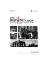
6.1.1 Safety-Related Inputs
The module generates an internal code sequence. This sequence is monitored by a safety
monitor (additional node) to ensure the correct order.
Figure 6.1 Code generator
The status of the externally connected mechanical switches influences the code sequence
transmission.
Information regarding the activation of the connected mechanical switches (e.g. if the
EMERGENCY STOP button is pressed, code transmission is interrupted) is transmitted as
follows:
The code words 0000, XX00 and 00XX prompt the safety monitor to put the installation in safe
mode (for instance using the EMERGENCY STOP button), without reporting a fault. If a code
word bit differs from the target code word, the safety monitor will switch the installation to safe
mode and will indicate a slave fault.
The two input channels on the safety monitor are independent. The safety monitor can be
programmed to monitor the input synchronicity for dual-channel applications.
6.1.2 Cross circuit monitoring of inputs
The inputs are monitored for cross circuits. The cross circuit monitoring function is able to
detect low-ohm cross circuits caused by a metallic connection between the two inputs.
Activated input channel
Codebit
3 2 1 0
1 X X 0 0
2 0 0 X X
1 and 2 0 0 0 0
None X X X X
1)
Table 6.1
1)
= working state
DI1
DI0
DI2
DI3
S1
S2
AS-i Bus
AS-i Chip
to Outputs
Strobe
Code-
Generator

VAA-2E2A-G12-SAJ/EA2L
Operation
205098 2014-11
15
6.1.3 Safety Classification
The module contains two independent, redundant input channels. If both input channels are
used, the module is suitable up to category 4/PL e in accordance with ISO 13849-1, or SIL 3 in
accordance with EN/IEC 62061. In this case, the monitor must be programmed so that dual-
channel switching is monitored.
If two single-channel switches are used, the module is suitable up to category 2/PL c in
accordance with ISO 13849-1,or SIL 2 in accordance with EN/IEC 62061.
6.1.4 Non safety-integrated outputs
The outputs are designed in line with AS interface standards. Positive potential is applied to
these outputs (PNP technology).
The status of the outputs is either determined by the master device or derived from the status of
the inputs, depending on the operating mode set via the parameters on the AS interface master
device.
The outputs can be operated in two modes:
■
The outputs are controlled directly by the AS interface master device via the related data
bits.
■
The output signals from the AS interface master device are linked with the safe inputs.
The outputs are activated by the master device or when the status of the inputs is safe.
The purpose of this operating mode is to control signal lamps which indicate the status of
the inputs without assistance from the master device.
Mode and logic table for outputs
The master device selects the modes via parameter bit P1:
P1 S1 / S2
1)
DO0 / DO1
2)
OUT1 / OUT2 Mode
1 X / X 0 / 0 0 / 0 Outputs independent from
the inputs
X / X 1 / 1 1 / 1
0 0 / 0 X / X 1 / 1 Open switch at input sets
the related output
1 / 1 0 / 0 0 / 0 The master device controls
the output if the switch at
the input is closed
1 / 1 1 / 1 1 / 1
Table 6.2
1)
0 refers to an open switch (safe status). 1 means a closed switch. X means any status
that does not effect the outputs.
2)
1 means outputs are activated, 0 means outputs are voltage-free.
UAUX
24 V
PELV
OUT1≥1
P1
S1
DO0
AS-i
Chip
AS-i
Bus

205098 2014-11
16
VAA-2E2A-G12-SAJ/EA2L
Maintenance and repair
7 Maintenance and repair
Regular function tests may be necessary, depending on the safety category.

VAA-2E2A-G12-SAJ/EA2L
Maintenance and repair
205098 2014-11
17

Subject to modifications
Copyright PEPPERL+FUCHS • Printed in Germany
www.pepperl-fuchs.com
FACTORY AUTOMATION –
SENSING YOUR NEEDS
Worldwide Headquarters
Pepperl+Fuchs GmbH
68307 Mannheim · Germany
Tel. +49 621 776-0
E-mail: [email protected]
USA Headquarters
Pepperl+Fuchs Inc.
Twinsburg, Ohio 44087 · USA
Tel. +1 330 4253555
E-mail: [email protected]
Asia Pacific Headquarters
Pepperl+Fuchs Pte Ltd.
Company Registration No. 199003130E
Singapore 139942
Tel. +65 67799091
E-mail: [email protected]
205098 / DOCT-1396A
11/2014
/