Page is loading ...

HP-5079-6
AC Speed Controller
US2 Series
OPERATING MANUAL
Thank you for purchasing an Oriental Motor product.
This Operating Manual describes product handling procedures and safety precautions.
• Please read it thoroughly to ensure safe operation.
• Always keep the manual where it is readily available.

−2−
1 Introduction ......................................................... 3
1.1 Before using the product ...................................... 3
1.2 Related operating manuals..................................3
2 Safety precautions ............................................. 4
3 Preparation ........................................................... 5
3.1 Checking the product ............................................ 5
3.2 How to identify the product model .................. 5
3.3 Information about nameplate ............................ 5
3.4 Products possible to combine ............................ 6
3.5 Names and functions of parts .............................8
4 Installation ............................................................ 9
4.1 Installation location ................................................9
4.2 Installing the speed controller ............................9
5 Connection .........................................................11
5.1 Connecting the power supply ..........................11
5.2 Connecting the motor and speed
controller ..................................................................12
5.3 Grounding ................................................................12
5.4 Connecting input signals ...................................13
6 Operation ............................................................14
6.1 Operation procedure ...........................................14
6.2 To adjust the motor rotation speed ................15
6.3 To switch the motor rotation direction .........15
7 Convenient functions .....................................16
7.1 Functions list ...........................................................16
7.2 Panel displays and setting items ......................17
7.3 Data locking for the set data .............................18
7.4 Display after setting the speed reduction
ratio ............................................................................18
7.5 Soft start/soft stop function ..............................19
7.6 Limiting the setting range of the rotation
speed .........................................................................20
7.7 Operating with external signals .......................20
8 Alarms ...................................................................21
9 Troubleshooting ...............................................22
10 Maintenance and inspection .......................23
10.1 Inspection ................................................................23
10.2 Warranty ...................................................................23
10.3 Disposal .....................................................................23
11 Cable and peripheral equipment
(sold separately) ................................................ 24
12 Regulations and standards ...........................25
12.1 UL Standards, CSA Standards ............................25
12.2 CE Marking ...............................................................25
12.3 RoHS Directive ........................................................25
12.4 Republic of Korea, Radio Waves Act ...............25
12.5 Conformity to the EMC ........................................26
13 Specications ..................................................... 28
13.1 Specications ..........................................................28
13.2 General specications ..........................................28
Table of contents

Introduction
−3−
1 Introduction
1.1 Before using the product
Only qualied personnel of electrical and mechanical engineering should work with the product.
Use the product correctly after thoroughly reading the section "Safety precautions." In addition, be sure to observe the
contents described in warning, caution, and note in this manual.
The product described in this manual has been designed and manufactured to be incorporated in general industrial
equipment. Do not use for any other purpose. Oriental Motor Co., Ltd. is not responsible for any damage caused through
failure to observe this warning.
1.2 Related operating manuals
Operating manuals are not included with the product. Download from Oriental Motor Website Download Page or
contact your nearest Oriental Motor sales oce.
Operating manual name Operating manual number
Speed controller US2 Series OPERATING MANUAL (this document) HP-5079
Motor
SCM Motor OPERATING MANUAL HM-9421
SCM Motor Right Angle Shaft Hypoid Gear JH/JL Gearhead
OPERATING MANUAL HM-9423
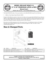
Names of parts
Connecting
Speed control motor
Gearhead
Power supply cable
Speed controller (rear side)
Speed controller
Cable xing
part
A capacitor is incorporated.
A cable tie for
xing a cable is
attached.
Input signal terminal
Function switching key
Acceleration/deceleration
time potentiometer
Front
panel
Protective
Earth
Terminal
Operating
Connecting
Connecting
Convenient functions
When the front panel is removed
Operation switch
Rotation direction
switch
Setting dial
Motor connector
Power supply
connector
p.16
p.11
p.11
p.11
p.14

Safety precautions
−4−
2 Safety precautions
The precautions described below are intended to prevent danger or injury to the user and other personnel through safe,
correct use of the product. Use the product only after carefully reading and fully understanding these instructions.
WARNING
Handling the product without observing the instructions that accompany a "Warning" symbol
may result in serious injury or death.
CAUTION
Handling the product without observing the instructions that accompany a "Caution" symbol
may result in injury or property damage.
Note The items under this heading contain important handling instructions that the user should
observe to ensure safe use of the product.
Explanation of graphic symbols
Indicates "prohibited" actions that must not be
performed.
Indicates "compulsory" actions that must be
performed.
WARNING
• Do not use the product in explosive or corrosive environments, in the presence of ammable gases, in places
subjected to splashing water, or near combustibles. Doing so may result in re, electric shock or injury.
• Do not transport, install the product, perform connections or inspections when the power is on. Always turn the
power o before carrying out these operations. Accidental contact may result in electric shock.
• The terminals on the rear side of the speed controller marked with symbol indicate the presence of high
voltage. Do not touch the CN1 and CN2 while the power is supplied. Doing so may result in re or electric shock.
• Do not touch the connector of the speed controller immediately after the power is turned o (for a period of
1minute). Accidental contact may result in electric shock.
• Do not touch the speed controller when conducting insulation resistance measurement or dielectric strength test.
Accidental contact may result in electric shock.
• Do not disassemble or modify the speed controller. Doing so may result in electric shock or injury.
• Only qualied and educated personnel should be allowed to perform installation, connection, operation and
inspection/troubleshooting of the product. Handling by unqualied and uneducated personnel may result in re,
electric shock, injury or damage to equipment.
• Install the speed controller in an enclosure. Failure to do so may result in electric shock or injury.
• Observe the rated range for the AC power supply voltage to input to the speed controller. Failure to do so may result
in re or damage to equipment.
• Securely connect and ground in accordance with the connection diagram. Failure to do so may result in re or
electric shock.
• Be sure to observe the specied cable sizes. Failure to do so may result in re.
• Use a motor and speed controller only in the specied combination. Failure to do so may result in re, electric shock
or damage to equipment.
• Always turn o the power before performing maintenance or inspection. Failure to do so may result in electric shock.
CAUTION
• Do not use the speed controller beyond its specications. Doing so may result in electric shock, injury or damage to
equipment.
• Keep the area around the speed controller free of combustible materials. Failure to do so may result in re or a skin
burn(s).
• Do not leave anything around the speed controller that would obstruct ventilation. Doing so may result in damage
to equipment.
• Do not wire the electromagnetic contactor or power relay between the motor and speed controller. To switch the
rotation direction using the electromagnetic contactor may cause damage to equipment.
• Do not use the product in elevating applications (vertical drives). Doing so may result in injury or damage to equipment.
• If an alarm of the speed controller is generated, remove the cause before resetting the alarm. Failure to do so may
result in injury or damage to equipment.
• Securely install the speed controller to the mounting plate. Inappropriate installation may cause the speed controller
to detach and fall, resulting in injury or equipment damage.
• Provide an emergency-stop device or emergency-stop circuit external to the equipment so that the entire
equipment will operate safely in the event of a system failure or malfunction. Failure to do so may result in injury.
• Be sure to ground the speed controller to prevent it from being damaged by static electricity. Failure to do so may
result in re or damage to equipment.
• If abnormal conditions occurred, stop the operation immediately and turn o the speed controller power. Failure to
do so may result in re, electric shock or injury.

Preparation
−5−
3 Preparation
This section explains the items you should check, as well as the name and function of each part.
3.1 Checking the product
Verify that the items listed below are included.
Report any missing or damaged items to the branch or sales oce from which you purchased the product.
The model name purchased means the set of the speed controller and power supply cable. Verify the model name
shown on the package label.
Refer to "3.4 Products possible to combine" on p.6 for combinations of the motor and speed controller.
□Speed controller .................................... 1 unit
□Instructions and Precautions for Safe Use
............................................................ 1 copy
□Power supply cable [2 m (6.6 ft.)] ........1 piece
Only for models supplied with the cable
Lead wire for frame ground connection (green, 1 piece)
A plug is attached with only the cables for the single-phase
100 VAC type.
The cables with a plug are for Japanese domestic market only.
3.2 How to identify the product model
US2D 25 - JA -CC
①Speed controller type US2D: US2 Series speed controller
②Output power 6: 6 W 15: 15 W 25: 25 W
40: 40 W 60: 60 W 90: 90 W
③Power supply voltage
JA: Single-phase 100 VAC
JC: Single-phase 200 VAC
UA: Single-phase 110/115 VAC
EC: Single-phase 220/230 VAC
④Power supply cable -CC: Included
Blank: Not included
3.3 Information about nameplate
The gure shows an example.
The position describing the information may vary depending on the product.
•Speed controller
•Motor
Speed controller specications
Manufacturing date
Speed controller model
Serial number
SPEED CONTROLLER
MODEL
ORIENTAL MOTOR CO.,LTD.
TOKYO 110-8536 JAPA N
MADE IN XXXXX
MODEL
SPEED CONTROL
MOTOR
ORIENTAL MOTOR CO.,LTD.
TOKYO 110-8536 JAPA NMADE IN XXXXX
фսդ०ऄؠڑ࠵ऄԈߑ
Ӳଭդ०Бސଇڔѫ॑ Ӳଭ֪ޙߎ
ଋࢽґܔࢽґܔङ
Motor model
Motor specications
Serial number
Manufacturing
date

Preparation
−6−
3.4 Products possible to combine
Be sure to match the output power and power supply voltage of the motor with those of the speed
controller.
Add -N to the end of the model name 4 when the power supply cable is not supplied.
The box (o) in the model name indicates the number representing the gear ratio.
In the case of the round shaft type, enter "A" instead of "GV," "GVH," or "GVR" that indicates the motor shaft type of 2 .
Motor Gearhead
Speed
controller
Power supply
cable
Parallel shaft gearhead GV gearhead
Output
power Power supply voltage
Speed control motor Speed controller
Model*Component products model*Model Component products model
1 2 3 4 5 6
6 W
Single-phase 100 VAC SCM26JA-oSCM26GV-JA
2GVoB
US2D6-JA-CC US2D6-JA CC02AC02P2
Single-phase 200 VAC SCM26JC-oSCM26GV-JC US2D6-JC-CC US2D6-JC
CC02AC02N2
Single-phase 110/115 VAC SCM26UA-oSCM26GV-UA US2D6-UA-CC US2D6-UA
Single-phase 220/230 VAC SCM26EC-oSCM26GV-EC US2D6-EC-CC US2D6-EC
15 W
Single-phase 100 VAC SCM315JA-oSCM315GV-JA
3GVoB
US2D15-JA-CC US2D15-JA CC02AC02P2
Single-phase 200 VAC SCM315JC-oSCM315GV-JC US2D15-JC-CC US2D15-JC
CC02AC02N2
Single-phase 110/115 VAC SCM315UA-oSCM315GV-UA US2D15-UA-CC US2D15-UA
Single-phase 220/230 VAC SCM315EC-oSCM315GV-EC US2D15-EC-CC US2D15-EC
25 W
Single-phase 100 VAC SCM425JA-oSCM425GV-JA
4GVoB
US2D25-JA-CC US2D25-JA CC02AC02P2
Single-phase 200 VAC SCM425JC-oSCM425GV-JC US2D25-JC-CC US2D25-JC
CC02AC02N2
Single-phase 110/115 VAC SCM425UA-oSCM425GV-UA US2D25-UA-CC US2D25-UA
Single-phase 220/230 VAC SCM425EC-oSCM425GV-EC US2D25-EC-CC US2D25-EC
40 W
Single-phase 100 VAC SCM540JA-oSCM540GV-JA
5GVoB
US2D40-JA-CC US2D40-JA CC02AC02P2
Single-phase 200 VAC SCM540JC-oSCM540GV-JC US2D40-JC-CC US2D40-JC
CC02AC02N2
Single-phase 110/115 VAC SCM540UA-oSCM540GV-UA US2D40-UA-CC US2D40-UA
Single-phase 220/230 VAC SCM540EC-oSCM540GV-EC US2D40-EC-CC US2D40-EC
60 W
Single-phase 100 VAC SCM560JA-oSCM560GVH-JA
5GVHoB
US2D60-JA-CC US2D60-JA CC02AC02P2
Single-phase 200 VAC SCM560JC-oSCM560GVH-JC US2D60-JC-CC US2D60-JC
CC02AC02N2
Single-phase 110/115 VAC SCM560UA-oSCM560GVH-UA US2D60-UA-CC US2D60-UA
Single-phase 220/230 VAC SCM560EC-oSCM560GVH-EC US2D60-EC-CC US2D60-EC
90 W
Single-phase 100 VAC SCM590JA-oSCM590GVR-JA
5GVRoB
US2D90-JA-CC US2D90-JA CC02AC02P2
Single-phase 200 VAC SCM590JC-oSCM590GVR-JC US2D90-JC-CC US2D90-JC
CC02AC02N2
Single-phase 110/115 VAC SCM590UA-oSCM590GVR-UA US2D90-UA-CC US2D90-UA
Single-phase 220/230 VAC SCM590EC-oSCM590GVR-EC US2D90-EC-CC US2D90-EC
* Enter “A” at the end of the model name for gearheads with an inch output shaft. Also, “B” at the end of the gearhead model
name in the component product name changes to “A.”
Reference
SCM 4 25 JA - 15
Parallel shaft gearhead GV gearhead
SCM 4 25 A - JA
Round shaft type
①Motor type SCM: Speed control motor
②Frame size 2: 60 mm (2.36 in.) 3: 70 mm (2.76 in.) 4: 80 mm (3.15 in.) 5: 90 mm (3.54 in.)
③Output power 6: 6 W 15: 15 W 25: 25 W 40: 40 W 60: 60 W 90: 90 W
④Power supply voltage JA: Single-phase 100 VAC JC: Single-phase 200 VAC
UA: Single-phase 110/115 VAC EC: Single-phase 220/230 VAC
⑤Gear ratio · Motor shaft type Number: Gear ratio of the gearhead A: Round shaft type
⑥Gearhead shaft type Blank: mm shaft type A: Inch shaft type

Preparation
−7−
Right-angle gearhead Hollow hypoid gear JH gearhead
Output
power Power supply voltage
Speed control motor Speed controller
Model Component products
model Model Component products model
1 2 3 4 5 6
25 W
Single-phase 100 VAC SCM425KJA-4HoBSCM425KJA
4HoB
US2D25-JA-CC US2D25-JA CC02AC02P2
Single-phase 200 VAC SCM425KJC-4HoBSCM425KJC US2D25-JC-CC US2D25-JC
CC02AC02N2
Single-phase 110/115 VAC SCM425KUA-4HoBSCM425KUA US2D25-UA-CC US2D25-UA
Single-phase 220/230 VAC SCM425KEC-4HoBSCM425KEC US2D25-EC-CC US2D25-EC
40 W
Single-phase 100 VAC SCM540KJA-5HoBSCM540KJA
5HoB
US2D40-JA-CC US2D40-JA CC02AC02P2
Single-phase 200 VAC SCM540KJC-5HoBSCM540KJC US2D40-JC-CC US2D40-JC
CC02AC02N2
Single-phase 110/115 VAC SCM540KUA-5HoBSCM540KUA US2D40-UA-CC US2D40-UA
Single-phase 220/230 VAC SCM540KEC-5HoBSCM540KEC US2D40-EC-CC US2D40-EC
90 W
Single-phase 100 VAC SCM590KJA-5HoBSCM590KJA US2D90-JA-CC US2D90-JA CC02AC02P2
Single-phase 200 VAC SCM590KJC-5HoBSCM590KJC US2D90-JC-CC US2D90-JC
CC02AC02N2
Single-phase 110/115 VAC SCM590KUA-5HoBSCM590KUA US2D90-UA-CC US2D90-UA
Single-phase 220/230 VAC SCM590KEC-5HoBSCM590KEC US2D90-EC-CC US2D90-EC
Right-angle gearhead Solid hypoid gear JL Gearhead
Output
power Power supply voltage
Speed control motor Speed controller
Model Component products
model Model Component products model
1 2 3 4 5 6
25 W
Single-phase 100 VAC SCM425KJA-4LoBSCM425KJA
4LoB
US2D25-JA-CC US2D25-JA CC02AC02P2
Single-phase 200 VAC SCM425KJC-4LoBSCM425KJC US2D25-JC-CC US2D25-JC
CC02AC02N2
Single-phase 110/115 VAC SCM425KUA-4LoBSCM425KUA US2D25-UA-CC US2D25-UA
Single-phase 220/230 VAC SCM425KEC-4LoBSCM425KEC US2D25-EC-CC US2D25-EC
40 W
Single-phase 100 VAC SCM540KJA-5LoBSCM540KJA
5LoB
US2D40-JA-CC US2D40-JA CC02AC02P2
Single-phase 200 VAC SCM540KJC-5LoBSCM540KJC US2D40-JC-CC US2D40-JC
CC02AC02N2
Single-phase 110/115 VAC SCM540KUA-5LoBSCM540KUA US2D40-UA-CC US2D40-UA
Single-phase 220/230 VAC SCM540KEC-5LoBSCM540KEC US2D40-EC-CC US2D40-EC
90 W
Single-phase 100 VAC SCM590KJA-5LoBSCM590KJA US2D90-JA-CC US2D90-JA CC02AC02P2
Single-phase 200 VAC SCM590KJC-5LoBSCM590KJC US2D90-JC-CC US2D90-JC
CC02AC02N2
Single-phase 110/115 VAC SCM590KUA-5LoBSCM590KUA US2D90-UA-CC US2D90-UA
Single-phase 220/230 VAC SCM590KEC-5LoBSCM590KEC US2D90-EC-CC US2D90-EC
Reference
SCM 4 25 K JA - 4 H 15
B
Right-angle gearhead
①Motor type SCM: Speed control motor
②Frame size 4: 80 mm (3.15 in.) 5: 90 mm (3.54 in.)
③Output power 25: 25 W 40: 40 W 90: 90 W
④Combined motor K: Round shaft type (with key)
⑤Power supply voltage JA: Single-phase 100 VAC JC: Single-phase 200 VAC
UA: Single-phase 110/115 VAC EC: Single-phase 220/230 VAC
⑥Frame size of combined motor 4: 80 mm (3.15 in.) 5: 90 mm (3.54 in.)
⑦Gearhead type H: JH gearhead L: JL gearhead
⑧Gear ratio Number: Gear ratio of the gearhead

Preparation
−8−
3.5 Names and functions of parts
Display
Front panel
Rotation direc
tion
switch
Operation
switch
Setting dial
Protective lm
Use after removing
the protective lm.
Front side When the front panel is attached
FUNCTION key
Mounting hole
(2 locations)
ESC key
Acceleration/
deceleration time
potentiometer
Protective lm
Use after removing
the protective lm.
Front side When the front panel is removed
Display This display shows the monitor item,
alarms, etc. ESC key This key is used to return to the previous
level.
Operation switch
Setting the operation switch to the "RUN"
side causes the motor to rotate.
Setting the operation switch to the
"STAND-BY" side causes the motor to stop.
FUNCTION key This key is used to switch the function.
Setting dial
This setting dial is used to change the
rotation speed and parameters.
After changing, the new value is
determined by pressing the setting dial.
Acceleration/
deceleration time
potentiometer
This potentiometer is used to set the
acceleration/deceleration time.
Rotation direction
switch
This switch is used to change the motor
rotation direction.
Mounting hole
(2places)
Installs the speed controller with screws
(M4).
Fix as shown in the gure.
This can prevent from giving stress
to the connector terminal caused b
y
movement of a cable.
Input sig
nal terminal
Motor connector
Power supply
connector
Rear side
Cable xing part
Motor connector Connects the motor connector. Input signal terminal Connects only when the motor is
operated using external signals.
Power supply
connector Connects the AC power supply. Cable xing part The motor cable can be xed using a
supplied cable-tie.

Installation
−9−
4 Installation
This chapter explains the installation location and installation methods.
4.1 Installation location
The speed controller described in this manual has been designed and manufactured to be incorporated in general
industrial equipment.
Install it in a well-ventilated location that provides easy access for inspection. The location must also satisfy the following
conditions:
• Indoors
• Operating ambient temperature: 0 to +50 °C [+32 to 122 °F] (non-freezing)
• Operating ambient humidity: 85% or less (non-condensing)
• Area that is free of explosive atmosphere or toxic gas (such as sulfuric gas) or liquid
• Area not stored combustible materials
• Area not exposed to direct sun
• Area free of excessive amount of dust, iron particles or the like
• Area not subject to splashing water (rain, water droplets), oil (oil droplets) or other liquids
• Area free of excessive salt
• Area not subject to continuous vibration or excessive shocks
• Area free of excessive electromagnetic noise (from welders, power machinery, etc.)
• Area free of radioactive materials, magnetic elds or vacuum
• Altitude Up to 1000 m (3300 ft.) above sea level
4.2 Installing the speed controller
The speed controller is designed so that heat is dissipated via air convection.
There must be a clearance of at least 25 mm (0.98 in.) and 50 mm (1.97 in.) clearances in the horizontal and vertical
directions, respectively, between the speed controller and enclosure or other equipment within the enclosure.
Installation direction
Install the speed controller so that the front panel side is turned in the front direction or upward.
Mounting plate
Front direction
Mounting plate
Mounting plate
Upward direction
Note • Do not install any equipment that generates a large amount of heat or noise near the speed controller.
• If the ambient temperature of the speed controller exceeds the upper limit of the operating ambient
temperature, revise the ventilation condition or forcibly cool the area around the speed controller using a
fan in order to keep within the operating ambient temperature.

Installation
−10−
Installation method
Install the speed controller to a at metal plate oering excellent vibration resistance.
Remove the front panel of the speed controller and secure the two mounting holes using screws, washers, and nuts
(M4: not supplied). Tighten the screws until no gaps remain between the speed controller and mounting plate.
Screw (M4: not supplied)
Tightening torque: 0.4 to 0.7 N·m (3.5 to 6.1 lb-in)
2×Ø4.5 (
Ø0.177) or 2×M4
• Plate cutout for mounting
90±0.2 (3.54±0.008)
53 0 (2.09 0 )
+1 +0.04
Nut
Washer
Front panel
81 0 (3.19 0 )
+1 +0.04
[Unit: mm (in.)]
< Installation Example >
Note • If a washer is used, use the washer which outer diameter is Ø9 mm (Ø0.35 in.) or less.
• For screws to install the speed controller, keep 6 mm (0.24 in.) or
less for the length of a screw head with a washer.
The front panel cannot be installed if it is exceeded 6 mm (0.24 in.).
6 mm (0.24 in.)
or less
Removing and installing the front panel
Removing
Remove the front panel having
the under side.
Installing
Install the front panel after placing
it on the upper side of the front face
of the speed controller.
Dimension [mm (in.)]
Mass: 0.4 kg (0.88 lb.)
103 (4.06)
60 (2.36)
[0.5 (0.02)]
[0.5 (0.02)
]
[0.5 (0.02)]
15 (0.59)
4 (0.16)
11 (0.43)
122 max. (4.80 max.)
102.5 (4.04)
80 (3.15)
52 (2.05)
90
±0.5
(3.54
±0.02
)
2×ϕ4.5 (ϕ0.177)

Connection
−11−
5 Connection
This chapter explains how to connect the speed controller and motor, input signals, and power supply, as well as the
grounding method.
Power supply
Motor Speed controller
Power supply cabke
Motor cable
Cable xing part
The motor cable can be
tightened using a supplied
cable-tie.
Grounding
Grounding
5.1 Connecting the power supply
Connect the AC power supply to the CN1 on the speed controller.
When connecting, use a supplied power supply cable or provide a cable separately.
A lead wire for frame ground connection [green, 2 m (6.6 ft.)] is included in the supplied power supply cable.
The supplied power supply cable does not have the polarity.
The power supply cables supplied with the single-phase 100 VAC type are attached a plug. They can be used in Japanese
domestic market only.
How to connect to the CN1
The indication of the terminal varies depending on
the voltage of the product.
Single-phase 110/115 VAC, 200 VAC, 220/230 VAC
Single-phase 100 VAC
Connect the live side to terminal L or L1, and
the neutral side to terminal N or L2.
Ground the speed controller using a FG terminal.
Grounding
Connector model: GFKC2,5/3-ST-7,62
(PHOENIX CONTACT GmbH & Co. KG)
AC power
supply

Connection
−12−
Connecting the lead wire
Connect the lead wire of the supplied power
supply cable to the connector.
Insert the lead wire while pushing the button
of the orange color with a screwdriver.
Lead wire
Wi
re the lead wire
so that the tip pa
rt
(copper wires) does
not become loose.
Button of the
orange color
Screwdriver
[When a cable other than the supplied power supply cable is used]
• Applicable lead wire: AWG18 to 14 (0.75 to 2.0 mm2)
• Strip the insulation cover of the lead wire
10 mm (0.39 in.)
If crimp terminals are used, select the following terminals.
Manufacturer: PHOENIX CONTACT GmbH & Co. KG
Model: AI 0,75-10 [Conductor cross-sectional area: 0.65-0.82 mm2 (AWG18)]
AI 1-10 [Conductor cross-sectional area: 0.82-1.2 mm2 (AWG18)]
AI 1,5-10 [Conductor cross-sectional area: 1.25-1.8 mm2 (AWG16)]
AI 2,5-10 [Conductor cross-sectional area: 2.0-3.0 mm2 (AWG14)]
Note • When inserting the lead wires into the connector, prevent
the tip of the lead wires from spreading.
Short-circuiting the lead wires may cause damage to the
product.
• Do not connect the output of the inverter to CN1.
It may cause damage to the product.
Connecting the earth leakage breaker
Connect an earth leakage breaker to the power line of the speed controller to protect the primary circuit.
( Refer to p.25)
Recommended device: Mitsubishi Electric Corporation NV series
5.2 Connecting the motor and speed controller
Connect the motor cable connector to the CN2 on the speed controller.
Use a connection cable (sold separately) when extending the wiring distance between the motor and speed controller.
The connection cable can be connected up to 3 pieces. Flexible connection cables(sold separately) are also available.
Maximum extension distance between the motor and speed controller: 10.5 m (34.4 ft.)
[including 0.5 m (1.6 ft.) of the motor cable]
Note • Securely insert the motor connector into the speed controller, and x the cable so as not to give stress to
the connector terminal. Insecure connection may cause malfunction or damage to the motor or speed
controller.
• Use a motor and speed controller only in the specied combination. Unspecied combination may result in
unusual temperature rise or damage to the product.
5.3 Grounding
Be sure to ground a motor using the Protective Earth Terminal and the speed controller using the FG terminal.
Note Securely ground the motor and speed controller to prevent them from being damaged by static electricity.
Static electricity may cause damage to the products if they are not grounded.
Motor
Ground close to the motor at a shortest distance using the Protective Earth
Terminal of the motor. Protective Ear
th
Terminal
Grounding
Applicable crimp terminal:
Round crimp terminal with insulation cover
Terminal screw size: M4
Tightening torque: 1.0 to 1.3 N·m (8.8 to 11.5 lb-in)
Applicable lead wire: AWG18 (0.75 mm2) or thicker
Ø4.1 (0.16) or more
4.8 (0.19) or less
9.5 (0.37) or less
Unit: mm (in.)
Note Do not use screws other than the Protective Earth Terminal screw attached on the product.

Connection
−13−
Speed controller
Ground the speed controller using the FG terminal of the CN1
(power supply connector).
Grounding
5.4 Connecting input signals
When the motor is operated and stopped externally,
connect input signals to the TB1.
The operation using the front panel is set at the time
of shipment. Refer to p.20 for how to operate using input
signals (external commands).
• Applicable lead wire: AWG24 to 16 (0.2 to 1.25 mm2)
• Lead wire strip length: 11 mm (0.43 in.)
TB1 pin assignment
Indication Signal
name Description
1 FWD Forward input
2 REV Reverse input
3 GND Input signals
common
Connection example for input signals
All input signals of the speed controller are photocoupler inputs.
•This is a connection example for when the motor is operated using relays* and switches
1
2
3
TB1
FWD
REV
GND
2 kΩ
2 kΩ
Speed controller
0 V
+24 V
* For relays or transistors connecting to the input signals, use those of leakage current 1 mA or less.
Recommended relay: Contact rated load DC30 V 15 mA
•This is a connection example for when the motor is operated using programmable controller
3
1
2
TB1
FWD
REV
GND
2 k
2 k
Speed controllerProgrammable controller
0 V0 V
+24 V

Operation
−14−
6 Operation
6.1 Operation procedure
Refer to "Troubleshooting" if the motor does not rotate.
Refer to "Data locking for the set data" if the change of setting data is not allowed.
Refer to "Alarms" if the alarm code such as or others is displayed.
1
1
2
2
3
3
4
4
5
5
After connecting, operate the product as follows.
When the power is cycled, the motor will rotate at the rotation speed
determined at this time.
The display is lit
(rotation speed)
Operation switch
STAND-BY RUN
When the setting dial is turned, the display blinks and
the motor rotation speed is changed.
The amount of the rotation speed change varies
depending on the speed to turn the setting dial.
Rotation speed
Factory setting: 90 r/min
The motor rotates.
AC power ON
When the setting dial is pressed, the display blinks several times quickly.
The data is determined when the display changes to a lighting state.
Rotation speed
Data determined
Operation switch
RUN STAND-BY
Decelerate Accelerate
The motor stops.
Names of parts
Operation switch
Setting dial
Front panel
Display
p.18
p.21
p.22

Operation
−15−
6.2 To adjust the motor rotation speed
Operation switc
h
Setting dial
Variable speed range
50 Hz: 90 to 1400 r/min
60 Hz: 90 to 1600 r/min
Setting the operation switch to the "RUN" side causes the motor to rotate. Setting the
operation switch to the "STAND-BY" side causes the motor to stop. The speed while
the motor is rotating can be adjusted with the setting dial.
Turning the setting dial slowly
When the setting dial is turned to the right, the rotation speed accelerates by 1 r/min
increments. When the setting dial is turned to the left, the rotation speed decelerates
by 1 r/min increments.
The display blinks at this time.
Turning the setting dial quickly
The amount of the rotation speed change increases.
When the setting dial is pressed, the rotation speed is determined, and the display
changes to a lighting state.
The actual rotation speed is indicated while the display is lit.
• The rotation speed can be set up to 1600 r/min. However, when the product is used at 50 Hz, the motor cannot be
operated at the speed exceeding approximately 1420 r/min.
• The rotation speed can be set regardless of whether the motor rotates or stops.
6.3 To switch the motor rotation direction
The motor rotation direction can be changed with the rotation direction switch.
Rotation direction
switch
REV
Rotation direction when setting to "FWD" Rotation direction when setting to "REV"
FWD
The rotation direction of the gearhead output shaft varies depending on the gear ratio of the gearhead. Check the
operating manual of the motor. Change the rotation direction switch according to the gear ratio of the gearhead.
Note To change rotation direction of the motor, wait until the motor completely stops. If the rotation direction is
switched while the motor is operating, it may not be changed, or it may be taken a long time to change.

Convenient functions
−16−
7 Convenient functions
7.1 Functions list
Various setting can be performed when removing the front panel.
Display
• To display the rotation
speed of the gearhead
output shaft
• To display the conveyor
transfer speed
Parameter type Display Setting range Factory setting
Speed reduction ratio 1.00 to 9999 1.00
• Sets the speed reduction ratio when the rotation speed of the gearhead output shaft is displayed.
• The conveyor transfer speed [m/rim] can be displayed if the conveyor speed reduction ratio
calculated by the formula on p.18 is input.
• The number of digits to be displayed varies depending on the set speed reduction ratio. Refer to p.18
for the number of digits displayed.
To display the speed
increased by an external
mechanism
Parameter type Display Setting range Factory setting
Speed increasing ratio 1.00 to 5.00 1.00
• When increasing the motor rotation speed using the external mechanism and others, the
converted speed can be displayed.
• When setting the speed increasing ratio to other than 1.00, the speed increasing ratio will be eective.
To display the rst digit of
the rotation speed
Parameter type Display Setting range Factory setting
Lowest digit display xing (Not xed) (Fixed)
The lowest digit of the displayed rotation speed is xed to "0" on the display.
When displaying the value of the lowest digit, set this parameter to
(Not xed).
Operation
To start and stop the
motor by ON-OFF control
of the power supply
Parameter type Display Setting range Factory setting
Prevention of operation at
power-on alarm (Disable) (Enable)
Sets whether to enable or disable the "prevention of operation at power-on alarm."
When starting or stopping the motor by ON-OFF control of the power supply, set this parameter to
(Disable).
To start and stop the
motor externally
Parameter type Display Setting range Factory setting
External operation signal input (Front panel)
(External commands)
The operation method can be selected between the front panel and external input signals.
If
(external commands) is selected, the input signals are enabled, and the operation switch and
rotation direction switch are disabled. Refer to p.20 for details.
To change the
acceleration time and
deceleration time of the
motor
Parameter type Display Setting range Factory setting
Acceleration/deceleration time (Disable) (Enable)
Sets whether to enable or disable the acceleration/deceleration time potentiometer of the front
panel. Refer to p.19 for details.
If on (Enable) is selected, the acceleration time and deceleration time can be set using the
acceleration/deceleration time potentiometer.
Speed setting
To limit the setting range
of the rotation speed
Parameter type Display Setting range Factory setting
Speed upper limit
90 to 1600
1600
Speed lower limit 90
The setting range of the rotation speed is set to 90 to 1600 r/min at the time of shipment.
The upper and lower limits of this setting range can be limited. Refer to the next page for details.
Lock
To lock the data The data can be locked so that the set value does not change.
Refer to p.18 for details.
Initialization
To initialize the data The data can be restored to the factory setting.
Refer to the next page, and execute the "data initialization."

Convenient functions
−17−
7.2 Panel displays and setting items
: Turn the setting dial : Press the ESC key : Press the FUNCTION key: Press the setting dial
E E
F
F
EF
∗1
EFE
EFE
EFE
EFE
EFEE
E
E
∗1
∗1
EFE
EFE
∗1
EF
∗1 It cannot be performed while the motor is operated.
“ ” will be displayed.
∗
2
It is not displayed while the data is locked.
Speed
reduction ratio Data setting
FWD input
REV input
The LED is lit while the input
signal is ON, and it is unlit when
the input signal is OFF.
Power ON
Rotation speed monitor
Input signal monitor
The motor rotation speed is displayed.
The display of the lowest digit is xed to " 0" at the time
of shipment.
[Display at the converted value]
When the "speed reduction ratio" or "speed increasing
ratio" is set to the value other than 1.00, the converted
value is displayed.
[Display of the setting speed]
If the setting dial is pressed while the operation switch is
set to STAND-BY, the setting speed is displayed.
Rotation speed monitor
Data setting
The data can be locked so that the set value does not change
.
Set on the rotation speed monitor screen
If the ESC key is pressed and hold more than
5 seconds, " " blinks on the display.
If the ESC key is pressed and hold more than
5 seconds while the data is locked, " "
blinks on the display.
Reset:
Lock the setting data
Lock:
If the ESC key is pr essed while the speed is changing by
turning the setting dial (the display is blinking), the motor
speed returns to the rotation speed before the change.
Execution
Retrun to the "speed reduction ratio"
Data
initialization∗2
Speed
increasing ratio Data setting
Lowest digit
display fixing Data setting
Prevention of
operation at
power-on alarm Data setting
Speed upper
and lower limit Data setting
Speed
upper limit
Data setting
Speed
lower limit
Data setting
Acceleration/
deceleration
time
Data setting
External
operation
signal input
Input signal
monitor
Note Do not turn o the power supply while the display is blinking after executing the data setting or initialization.
Doing so may damage the data.

Convenient functions
−18−
7.3 Data locking for the set data
The setting can be locked so that the set rotation speed and parameters do not change.
The setting of data and parameters cannot be changed using the setting dial while the
data is locked.
However, the setting data of each parameter can be checked even when the data is
locked.
Remove the front panel when executing the data locking. ESC key
Rotation speed monitor
Locking
Lock
Press and hold the ESC key
(about 5 seconds)
Rotation speed monitor
Reset locking
Reset
Press and hold the ESC key
(about 5 seconds)
•Display while the data is locked
If you try to change the data while the data is locked, " " is displayed for about 1 second.
7.4 Display after setting the speed reduction ratio
Display of the rotation speed
Display position of decimal point
The position of the decimal point displayed on the rotation speed monitor varies depending on the set speed reduction
ratio or speed increasing ratio as shown in the table below.
Setting value of the speed reduction
ratio and speed increasing ratio Display position of decimal point
1.00 to 9.99
10.00 to 99.99
100.0 to 999.9
1000 or more
In the case of motors with the JH gearhead and JL gearhead, use the actual gear ratio about the gear ratio of
gearhead. Check the operating manual of the motor for the actual gear ratio.

Convenient functions
−19−
Display the conveyor transfer speed
To display the conveyor transfer speed, set the conveyor speed reduction ratio, which is calculated using the formula
below, to the "speed reduction ratio" parameter.
≅ 79.6Conveyor speed reduction ratio = Gearhead gear ratio
Pulley diameter [m] × π =25
0.1 [m] × π
Fr
om the conversion formula, the conveyor speed reduction ratio is calculated as 79.6 in this example.
When the "speed reduc
tion ratio" parameter is set to "79.60" and the motor rotation speed is 1300 r/min,
the con
veyor transfer speed is converted as follows:
≅16.3
1300
79.60
Conveyor transfer speed [m/min] =
Accordingly, "16.3" is shown on the panel. The display varies depending on the setting of the "lowest digit display
xing" parameter. 16.0 is displayed at the time of shipment.
Conveyor
transfer speed
Pulley
diameter
==
1
Feed rate per motor revolution
Gearhead gear ratio
Pulley diameter [m] × π
Conveyor transfer speed [m/min] = Motor output shaft rotation speed [r/min]
Conveyor speed reduction ratio
When the calculated conveyor speed reduction ratio is used,
the conveyor transfer speed is converted as follows:
Example:
The pulley diameter is 0.1 m and gear ratio of the gear head is 25
Conveyor speed
reduction ratio
7.5 Soft start/soft stop function
An impact on a load is suppressed by soft start/stop operation of the motor, and the motor starts running smoothly .
The acceleration time and deceleration time is xed to about 1 second at the time of shipment.
When adjusting the acceleration time and deceleration time, change the setting of the "acceleration/deceleration time"
parameter.
If this parameter is set to ON, the acceleration/deceleration time can be adjusted using the acceleration/deceleration
time potentiometer.
Setting range of the acceleration/deceleration time potentiometer: 0.1 to 15.0 seconds
The actual acceleration time and deceleration time against the setting vary depending on the load inertia and frictional
load.
Acceleration/deceleration
time potentiometer
The numbers "0" and "10" on the
potentiometer in the gure are not
indicated on the product.
0
10
0
5
10
15
Time [s]
Acceleration/deceleration time
potentiometer characteristics
(representative values)
246810
Acceleration/deceleration time
potentiometer [scale]
Rough indications of the
time against the scale
0.1 s
15 s
1 s
•Acceleration time
The acceleration time is set as the time needed for the motor to reach the
1000 r/min from the standstill state.
•Deceleration time
The deceleration time is set as the time needed for the motor to stop from
the 1000 r/min.
If the deceleration time is set shorter than the time for coasting stop of the
motor, the motor will not stop at the specied time.
Acceleration timeDeceleration time
[r/min]
Actual set
rotation speed
1000
Ti
me

Convenient functions
−20−
7.6 Limiting the setting range of the rotation speed
The setting range of the rotation speed using the setting dial can be limited by setting the upper limit and lower limit.
[r/min
]
[r/min
]
[Example]
When limiting the speed rang
e
by setting to the speed upper
limit to 1200 r/min and the
speed lower limit to 200 r/min
90 1600
200 1200
Factory setting
(initial value)
Speed setting range
•Speed upper limit
The upper limit of the rotation speed can be set in the "speed upper limit" parameter.
If the rotation speed exceeding the speed upper limit is already set, the rotation speed set in the "speed upper limit"
parameter will be overwritten.
•Speed lower limit
The lower limit of the rotation speed can be set in the "speed lower limit" parameter.
If the rotation speed below the speed lower limit is already set, the rotation speed set in the "speed lower limit" will be
overwritten.
7.7 Operating with external signals
When the motor operation/standstill and rotation direction change are performed by ON/OFF-control of the input
signals, disable the operation switch and rotation direction switch.
When the motor is operated externally, set the "external operation signal input" parameter to " ."
If the operation switch or rotation direction switch is operated when the "external operation signal input" parameter is
set to " ," " " is displayed for about 1 second.
ON
OFF
ON
OFF
REV input
FWD input
Motor movement
Fo
rward direction
Reverse direction
Operation/standstill
Operation/standstill
FWD input REV input Motor shaft action
ON OFF Rotates in the forward direction
OFF ON Rotates in the reverse direction
OFF OFF Standstill
ON ON
The motor rotation direction varies depending on the
gear ratio of the gearhead or the setting of the rotation
direction switch. Refer to p.15 for rotation direction of the
motor.
Note To change rotation direction of the motor, wait until the motor completely stops.
If the rotation direction is switched while the motor is operating, it may not be changed, or it may be taken a
long time to change.
/