Town & Country Fireplaces TC36/TC36 Arch Installation guide
- Category
- Fireplaces
- Type
- Installation guide

Visit www. townandcountryfireplaces.net for the most recent version of this manual
191023-16 SKU# 22150017 100005912
INSTALLER: Leave this manual with the appliance.
CONSUMER: Retain this manual for future reference.
TC36D
COUNTRY HOME
BURNER KIT
INSTRUCTIONS
(NATURAL GAS ONLY)
SKU# 22150017
For TC36D & TC36D Arch
Series D
These instructions are supplementary to the
Installation and Operating Instructions supplied
with the replace and should be kept together.
Refer to the Installation and Operating Instructions
for proper gas supply, safety requirements and
operating instructions

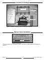
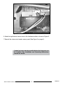
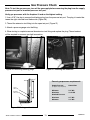
1. Place the keyhole slots of the burner (Figure 3) over the two screws located on the rebox oor
(Figure 2).
Screws
Burner/ Grate Installation
SKU# 22150017 191023-16
2
100005912
Contents of Package
Figure 2: Firebox base.
Figure 1: TC36 and TC36 Arch Country Home burner kit contents.
7Pcs Log Set
Air Deector
Ember Material
Burner Assembly
Log Grate

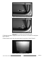
2. Slide the burner back to engage the screws in the small part of the keyhole slot and tighten
screws (Figure 4).
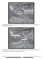
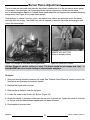
3. Remove access cover to the valve control center from right side of rebox (Figure 5)
SKU# 22150017 191023-16 3100005912
Figure 5: Access cover to valve control center.
Figure 4: Burner assembly pushed back against right
side screw.
Figure 3: Burner assembly over top of right side screw.

Ignition and sensor wires
Bulkhead plate
5. Feed the ignition and sensor wires through the bulkhead plate to the interface module. Tuck the
ignition and sensor wires below the supply tubes (Figure 7).
4. Attach the pilot and gas supply tubes to the bulk head tting and tighten (Figure 6). Ensure the
connections are gas tight.
SKU# 22150017 191023-16
4
100005912
Figure 7: Ignition and sensor wire routing.
Figure 6: Gas and supply tubes.

Ignition wire.
Flame sensor
wire.
Interface module
6. Attach the ignition and sensor wires to the Interface module as shown in Figure 8.
7. Reinstall the valve control center access panel (See Figure 5 on page 3).
A panel set must now be installed before the log grate can
be installed. See Installation and Operating Instructions
manual for details.
SKU# 22150017 191023-16 5100005912
Figure 8: Interface module.

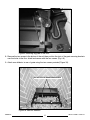
AIR DEFLECTOR SECURING SCREWS
8. Remove the two screws in the bottom of the unit then position the slots of the grate securing brackets
over the holes in the oor shield and secure with the two screws (Fig. # 9).
9. Attach rear deector to rear of grate using the two screws provided (Figure 10).
SKU# 22150017 191023-16
6
100005912
Figure 10: Rear air deector.
Figure 9: Securing log grate to the oor.

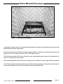
Ember Material Placement
A large bag of ember material is shipped with the replace and needs to be installed to ensure optimum
performance and ame appearance.
Pull apart the material into ember size pieces (approximately 1” squares) and gently place them into the
burner pan. Do not compress, leave it loose for best performance.
Fill the burner pan level with the top of the pan at rear, and gradually slope forward to the rebox oor at
the front, covering both burner tubes.
Place remaining ember material outside of the burner pan as desired to cover-up gas lines and brackets.
Note: Ember material placement and amount will affect ame appearance. More ember material results
in lower ame height. Add or remove as needed until desired ame affect.
GLOWING EMBERS
SKU# 22150017 191023-16 7100005912
Figure 11: Glowing Ember placement.

Log Set and Assembly
SKU# 22150017 191023-16
8
100005912

Note: Improper placement of logs will cause sooting on internal parts and glass. The logs
may need to be repositioned slightly to avoid excessive flame impingement.
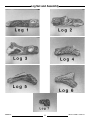
Log Placement
1
2
Gas plumbing and vent connections should be completed before proceeding.
The logs are fragile, and should be handled with care. Unpack and inspect log set. There should be a
total of seven logs.
Position the logs as indicated by the following pictures. The three main logs have holes and / or pins.
Engage each pin in the corresponding holes. The four smaller logs do not have holes or pins. They
rest in position. Locate as per the diagrams 12 through 19.
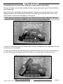
1. Place Log 1 onto the log grate with the thicker end on the right and engage the holes in the bottom of the log
onto the two pins on the log grate.
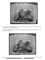
2. Place Log 2 onto the lef side of the log grate with the thicker end down and rest the log onto the long pin on
the side of the log grate then engage the hole in the bottom of Log 2 onto the pin in the top left of Log 1.
SKU# 22150017 191023-16 9100005912
Figure 12: First log placement.
Figure 13: 2nd log placement.

4
3
3. Place Log 3 on an angle and engage the holes in the bottom of Log 3 onto the pin in the back corner of the
log grate and the pin in the middle of Log 1.
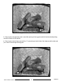
4. Place Log 4 onto log grate resting on the second nger from the left and the narrow part pointing towards
the center of the log grate.
SKU# 22150017 191023-16
10
100005912
Figure 14: 3rd log placement.
Figure 15: 4th log placement.

5
6
5. Place Log 5 on the right front panel, around the right leg of the log grate and with the charred end pointing
towards the center of the replace.
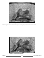
6. Place Log 6 on the left front panel with the “Y” end pointing to the left side of the replace and the other end
just in front of the left leg of the log grate.
SKU# 22150017 191023-16 11 100005912
Figure 16: 5th log placement.
Figure 17: 6th log placement.

3
21
5
6
7
4
7
7. Place Log 7 in the front center of the replace, covering the joint between the two front panels.
SKU# 22150017 191023-16
12
100005912
Figure 18: 7th log placement.
Figure 19: Completed log placement.

SKU# 22150017 191023-16 13 100005912
1. Use a 3/16” Hex key to remove the blanking plug from the pressure test port. The plug is located be-
tween the right side lintel and rebox side (Figure 20).
2. Thread the extension test tting into the open test port (Figure 21)
3. Attach a pressure gauge onto the tting.
4. When testing is complete remove the extension test tting and replace the plug. Thread sealant
will be required to ensure a gas tight connection.
Correct gas pressure requirement:
Supply Pressure Natural Gas
(For purpose of input adjustment)
Minimum 5.0" WC
Maximum 13.9" WC
Manifold Pressure
Maximum 3.5" WC
Minimum 1.6" WC
Note: To test the gas pressure, turn off the gas supply before removing the plug from the supply
pressure test port or manifold pressure test port.
Verify gas pressures with the fireplace lit and on the highest setting.
Gas Pressure Check
SUPPLY
PRESSURE
MANIFOLD
PRESSURE
Figure 22: Testing port location
Figure 21: Attaching test extension. Figure 20: Removing blanking plugs.

Burner Flame Adjustment
SKU# 22150017 191023-16
14
100005912
Figure 23: Example of desirable ame appearance.
The air shutter on the burner tube controls the primary combustion air to the gas burner and is preset
at the factory for natural gas fuel. Some adjustment may be necessary to obtain desired ame
and to eliminate carbon deposits. Evaluate ame appearance after the replace has reached operating
temperature. See Figure 23 for proper ame pattern.
Open primary air shutter if the logs, glass, and rebox have carbon accumulation and/or the ames
are long, dark and stringy. The shutter may also be opened to enhance the ember material glow and
lessen the ame height.
PRIMARY AIR SHUTTER
(Shown in closed position)
Caution: Proper air shutter setting is a must. The flame should be just orange and “lazy”. It
should NEVER be set to create sooting on internal parts and glass.
To Adjust:
1. Open and remove window frame and set aside. See "Window Frame Removal" section found in the
Installation and Operating Instructions manual.
2. Remove the log set and set aside.
3. Remove the air deector from the log grate.
4. Loosen the screw in the Primary Air Shutter (Figure 24).
5. Rotate the shutter to increase or decrease the amount of primary air. Tighten the screw to hold the
air shutter once the desired ame appearance has been achieved.
6. Re assemble in reverse order.
Figure 24: Primary air shutter.

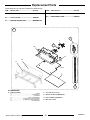
ITEM ....... DESCRIPTION ............................................PART NO.
#1..........COUNTRY HOME BURNER ASSY ... 22150017
#2..........7 PCS LOG SET ................................. 80001207
#3..........ORIFICE, NATURAL GAS ................. MARKED(“NI”)
ITEM ....... DESCRIPTION ............................................PART NO.
#4..........PILOT ASSEMBLY ............................. 80002855
#5..........MAIN SUPPLY TUBE ......................... 80002875
#1.... BURNER ASSEMBLY
1a......................................................................................GRATE
1b.........................................................................BURNER TRAY
1c................................................................................MANIFOLD
1d...........................................................TCCV PILOT BRACKET
1e..........................................BURNER TRAY SUPPORT SHIELD
1f...........................................BURNER TRAY SHIELD GASKET
1g......................................................................AIR DEFLECTOR
KIT CONTENTS:
#2 7 PCS LOG SET (not shown)
#3.... ORIFICE, NATURAL GAS(MARKED”NI”)
#4.... PILOT ASSEMBLY, CONVERTIBLE
#5.... MAIN SUPPLY TUBE
(WHEN ORDERING, INCLUDE PART NUMBER WITH DESCRIPTION)
Replacement Parts
1
5
4
3
1a
1d
1f
1e
1g
1c
1b
SKU# 22150017 191023-16 15 100005912
Figure 24: Primary air shutter.

For technical support, please contact your retailer
Web site: www.townandcountryfireplaces.net
2975 Allenby Rd., Duncan, BC V9L 6V8
Printed in Canada
© 2023 Copyright Pacic Energy Fireplace Products LTD
Reproduction, adaptation, or translation
without prior written permission is prohibited,
except as allowed under the copyright laws.
-
 1
1
-
 2
2
-
 3
3
-
 4
4
-
 5
5
-
 6
6
-
 7
7
-
 8
8
-
 9
9
-
 10
10
-
 11
11
-
 12
12
-
 13
13
-
 14
14
-
 15
15
-
 16
16


Town & Country Fireplaces TC36/TC36 Arch Installation guide
- Category
- Fireplaces
- Type
- Installation guide
Ask a question and I''ll find the answer in the document
Finding information in a document is now easier with AI