Page is loading ...


WARRANTY
Lowndes
Engineering
Co.,
Inc.
guarantees
each
new
LECO
Aerosol
Generator
to
the
extent:
that:
"For
a
period
of
one
(1)
year
from
date
of
purchase,
Lowndes
Eneering
Co.,
Inc.
will
repiaee,
free
of
charge,
any
part
or
parts
of
the
Generator
found,
upon
examination,
to
be
defeee
in
material
and/or
workmanship.
Such
examinatibn
shall
be
made
at
the
LECO
factory
in
Valdosta,
Georgia,
USA
or
at
any
point
designated
by
Lowndes
Engineering
Co.,
Inc.
The
examination
shall
be
made
by
a
person
or
persons
approved
by
Lowndes
Engineering
Co.,
Inc.
Any
part
or
parts
returned
under
provisions
of
this
Warranty
shall
be
returned
transportation
prepaid."
This
is
the
total
extent
of
the
Warranty.
The
following
are
specific
items
and/or
situations
not
covered
by
the
Warranty:
Engine
The
engine
is
subject
to
the
Warranty
of
its
manufacturer.
The
cost
of
labor
in
connection
with
replacement
or
repair
of
defective
parts.
A
Generator
upon
which
alterations
have
been
made.
Consequential
damages
or
contingent
liabilities
arising
out
of
the
failure
of
any
Generator
to
operate
properly.
So
Any
express,
implied
or
statutory
warranty
other
than
set
forth
above.
Copyright
(C)
1989,
1991
Lowndes
Engineering
Co.,
Inc.
All
fights
reserved
Manufactured
by
eoCLA'RKE
159
Ni-den
Ave.
POBox
72197
Roselle,
IL
60172
ENGINEERING
TECHNOLOGIES,
INC.
Phone"
(630)
894-2000
Fax"
(630)
582-0706

LECO
P-1
SPECIFICATIONS
Manuasue
LECO
P-l,
01/95
Revised
01/97
Engine
.Robin
Two-Cycle
Blower
LECO
Special
Design
Dispersal
Head
LECOe
Design
with
no
moving
pans
Insecticide
Tank
.35
Gallon
(1.32
Liters)
Polyethylene,
S/N
78001
thru
S/N
7800810
.66
Gallon
(2.50
Liters)
Polyethylene,
S/N
7800811
up
Insecticide
System
Pressufizexl
by
blower,
no
pump
nary
Controls
Consists
of
flow
control
valve
with
four
adjustable
flow
rate
settings
Net
Weight
(Empty)
17
Pounds
Shipping
Weight.
(Domestic)
22
Pounds
Shipping
Weight
(Export)
25
Pounds
Shipping
Cube
2.31
Feet
'REGISTRATION
THIS
MANUAL
IS
FOR
MY
LECO
AEROSOL
GENERATOR
LECO
MODEL
P-1
SERIAL
MBER
THE
ABOVE
INFORMATION.
WHICH
CANBE
FOUND
ON
THE
HANDLE
BRACE
OF
THE
MACHINE,
SHOULD
BE
FILLED
IN.
YOUR
PROMPT
ATrENTION
TO
THIS
MATI'ER
WILL
MAKE
IT
CONVENIENT
FOR
YOU
IN
THE
FWIXJRE,
AS
THIS
INFORMATION
MUST
BE
GIVEN
WHEN
ORDERING
PARTS.

FOREWORD
Every
effort
has
been
made
to
make
this
manual
as
complete
as
possible
so
that
it
will
provide
maximum
assistance
in
operating
and
maintaining
your
LECO
Cold
A6rosol
Fog
Generator.
This
manual
is
divided
generally
into
two
sections
Operating
and
Maintenance
Section
and
Illustrated
Parts
Section.
The
Operating
and
Maintenance
Section
contains
complete
instructions
for
operating
and
maintaining
your
LECO
Cold
Aerosol
Fog
Generator.
No
difficulty
should
be
encountered
in
following
them.
Before
attempting
to
start
your
unit
the
first
time,
study
the
complete
Operating
Instructions
carefully
and
identify
all
parts
referred
to.
You
will
find
that
the
operation
of
your
LECO
Cold
Aerosol
Fog
Generator
is
a
simple
matter
of
calibrating
the
flow
rate
and
operating
the
control
valve.
However,
like
all
mechanical
equipment,
your
unit
requires
a
certain
amount
of
maintenance.
The
Maintenance
Instructions
will
enable
your
LECO
Cold
Aerosol
Fog
Generator
to
give
you
continuous
and
trouble-free
service.
It
is
highly
recommended
that
some
system
be
established
to
assure
the
performance
of
this
maintenance
as
its
importance
cannot
be
over-emphasized.
The
Illustrated
Parts
Section
of
the
manual
is
made
up
of
exploded
views
and
parts
lists.
Every
part
of
the
unit
is
illustrated
and
identified
with
a
part
.number.
Always
order
parts
by
part
number,
description
and
the
serial
number
of
your
unit.
Although,
with
proper
maintenance,
your
unit
should
operate
indefinitely
without
any
trouble,
there
might
come
a
time
when
trouble
does
develop.
For
such
an
occasion,
a
complete
Trouble
Shooting
section
has
been
prepared
and
included
in
this
manual.

CONTENTS
FOREWORD
...........................................................
SCOPE
................................
...............................
DESCRIPTION
..........................................................
THEORY
OF
OPERATION
................................................
ENGINE
SPECIFICATIONS
(S/N
78001
thru
S/N
78001304)
........................
9
ENGINE
SPECIFICATIONS
(S/N
78001305
up)
...............................
ENGINE
PREPARATION
FOR
OPERATION
..................................
ENGINE
STARTING
PROCEDURE
(S/N
78001
thru
S/N
78001304)
10
ENGINE
STARTING
PROCEDURE
(S/N
78001305
up)
12
STOPPING
THE
ENGINE
................................................
13
ASSEMBLING
INSTRUCTIONS
...........................................
14
OPERATING
INSTRUCTIONS
............................................
14
CONTROL
VALVE
.....................................................
15
ENGINE
ADJUSTMENTS
16
ENGINE
MAINTENANCE
INSTRUCTIONS
17
PREPARATION
FOR
STORAGE
17
CONTENTS
ILLUSTRATED
PARTS
BREAKDOWN
SECTION
18
IIUSTRATED
PARTS
BREAKDOWN
19
ENGINE
PARTS
35
CARBURETOR
SERV/
MANUAL
(S/N
78001
thru
S/N
78001304)
53
TROUBLE
SHOOTING
CHECKLIST
(S/N
78001
thru
S/N
78001304)
62
CARBURETOR
SERVICE
MrUAL
(S/N
78001305---
up)
65
LECO
P1
TROUBLE
SHOOTING
CHECKLIST
67
CONVERSION
TABI.I:
..................................................
15
CALIBRATING
INSTRUCHqONS
...........................................
15


SCOPE
This
manual
provides
the
description,
theory
of
operation,
operating
instructions,
calibrating
instructions,
maintenance
instructions
and
illustrated
parts
breakdown
for
the
LECO
P-1
Aerosol
Generator.
DESCRIPTION
The
LECO
P-1
Aerosol
Generator
is
designed
for
indoor
and
outdoor
use.
It
consists
of
a
centrifugal
blower
driven
by
a
2-cycle
gasoline
engine,
a
discharge
head,
an
insecticide
tank
and
insecticide
flow
control
valve
with
four
adjustable
flow
rate
settings.
The
Generator
is
a
complete
hand
held
unit
weighing
only
17
pounds.
See
Figure
1.
THEORY
OF
OPERATION
The
LECO
P-1
Generator
is
designed
for
dispersing
insecticides
at
an
Ultra
Low
Volume
(ULV)
rate
with
droplets
of
optimum
size.
The
insecticide
is
forced
from
the
tank
through
the
system
by
air
pressure
obtained
from
the
blower.
The
insecticide
flows
from
the
tank
through
the
adjustable
control
valve
to
the
specially
designed
LECO
dispersing
head
where
it
is
sheared
into
optimum
size
droplets,
by
the
air
blast
from
the
blower
and
is
dispersed
into
the
atmosphere.
After
dispersal
the
droplets
stay
suspended
in
the
air
and
penetrate
the
insect
infested
areas.


ENGINE
SPECIFICATIONS
S/N
78001
thru
S/N
78001304
Engine
Type:
Displacement:
Starter:
Carburetor:
Lubrication:
Robin
Two-Cycle
22.5
cc
1.37
cu.
in.
Auto
Rewind
Fuel
Tank:
0.7
Liter
Spark
Plug:
NGK-
---BM7A
Champion
CJ4,
CJ6
Spark
Plug
Gap:
0.6/0.7
mm
All
Position-
Diaphragm
Type
Fuel-Oil
Mix
between
15
and
20
to
I
for
the
ftrst
20
hours.
Fuel-Off
Mix
between
20
and
25
to
1
thereafter.
Engine
Type:
Displacement:
Starter:
Carburetor:
Lubrication:
ENGINE
SPECIFICATIONS
S/N
78001305
up
Robin
Two-Cycle
Fuel
Tank:
0.6
Liter
2.2
c
Spark
Plug:
NGK
'---B/f7/
1.35
cu.
in.
Champion
CJ4,
CJ6
Auto
Rewind
Spark
Plug
Gap:
0.6/0.7
mm
All
Position
Diaphragm
Type
Fuel-Oil
Mix
between
15
and
20
to
1
for
the
first
20
hours.
Fuel-Off
Mix
between
20
and
25
to
1
thereafter.
ENGINE
PREPARATION
FOR
OPERATION
Fuel
and
Oil
Mixture
Inspect
the
fuel
tank
and
fill
with
clean,
flesh
fuel
of
the
proper
mixture.
This
engine
requires
a
mixture
of
gasoline
of
between
20
and
25
pans
gasoline
to
1
part
oil
(1
gal.
gasoline.,
to
6
oz.
oil)
of
regular
leaded
gasoline.
For
the
first
twenty
hours,
use
the
mixing
ratio
ofbetween
15
and
20
to
1.
DO
NOT
USE
BIA
OIL.
DO
NOT
MIX
GASOLINE
AND
OIL
DIRECFLY
IN
THE
ENGINE
FUEL
TANK.
IMPORTANT:
Failure
to
follow
proper
fuel
mix
instructions
could
result
in
serious
damage
to
the
engine.
CAUTION
When
preparing
fuel
mixture,
mix
only
the
amount
needed
for
the
job
you
are
to
do.
Do
not
use
fuel
mixture
that
has
been
stored
longer
than
two
(2)
months.
Fuel
mixture
stored
longer
than
this
will
cause
hard
starting
and
poor
performance.
If
fuel
mix
has
been
stored
longer
than
this
time
it
should
be
removed
and
filled
with
a
fresh
mixture.
_..'..
....
CAUTION!
NEVER
flll
the
fuel
tank
to
the
inlet
port
level.
NEVER
add
fuel
to
the
tank
in
a
closed
unventilated
area.
DO
NOT
add
fuel
to
this
unit
near
an
open
fire
or
spark.
BE
SURE
to
wipe
off
spilled
fuel
before
attempting
to
start
the
engine.
DO
NOT
attempt
to
refuel
an
extremely
hot
engine.

ENGINE
STARTING
PROCEDURE
S/N
78001
thnl
S/N
78001304
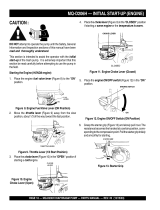
Fully
open
(fast)
Fully
closed
(idle)
Figure
3
1.
Put
the
throttle
in
fully
closed
(idle)
position.
See
Figure
3.
IF
ENGINE
IS
HOT,
SKIP
TO
STEP
5.
Primer
pump
Indicator
window
Figure
4
2.
Give
a
.gentle
push
to
the
primer
pump.
See
Figure
4.
Red
Figure
5
Stop
pushing
the
primer
pump
immediately
as
soon
as
the
fuel
mixture
appears
in
the
red
(upper)
section.
The
lower
section
is
green.
See
Figure
5.
10

ENGINE
STARTING
PROCEDURE,
continued
S/N
78001
thru
S/N
78001304
Stop
button
Partly
open
position
Figure
6
Depress
the
throttle
lever
completely,
push
the
stop
button
and
take
your
hand
off
of
lever.
The
stop
button
will
lock
the
throttle
lever
in
partly
open
position.
See
Figure
6.
Figure
7
5.
Pull
the
recoil
start
briskly.
See
Figure
7.
CAUTION:
Gradually
return
handle.
Do
not
let
it
snap
back.
Pull
the
rope
in
the
direction
of
the
starter
rotation.
Do
not
pull
the starter
rope
all
the
way
out
of
the
drum.
Let
the
engine
warm
up
by
running
it
at
a
low
RPM
(slow
speed)
for
approximately
one
or
two
minutes.
CALON
NEVER
OPERATE
THE
ENGINE
AT
HIGH
RPM
WITHOUT
LOAD.
With
throule
fltlly
opened
and
no
load,
the
engine
rpm
will
be
very
high
which
can
have
an
adverse
effect
on
the
life
of
the
engine.
.....,
<,.
<,
:i.
-,,;--.
5----.::,,..
II

ENGINE
STARTING
PROCEDURE
S/N
78001305
up
Fully
open
(fast)
Fully
closed
(idle)
Figure
8
1.
Put
the
throttle
in
fully
closed
(idle)
position.
See
Figure
8.
Figure
9
Push
the
primer
button
to
feed
the
fuel
to
the
carburetor
until
fuel
overflows
from
the
carburetor.
See
Figure
9.
Figure
10
3.
Close
the
choke
lever.
If
the
engine
is
warm
or
the
ambient
temperature
is
high,
dose
the
choke
lever
half-way,
or
keep
it
open
fully.
If
the
engine
is
cold,
or
the
ambient
temperature
is
low,
close
the
choke
lever.
See
Figure
10.
12

St
ENGINE
STARTING
PROCEDURE,
continued
S/N
78001305
up
Figure
11
Pull
the
recoil
start
briskly.
See
Figure
11.
CAUTION:
Gradually
return
handle.
Do
not
let
it
snap
back.
Pull
the
rope
in
the
direction
of
the
starter
rotation.
Do
not
pull
the
starter
rope
all
the
way
out
of
the
drum.
Figure
12
After
starting
the
engine,
gradually
open
choke
by
turning
the
choke
lever
and
finally
keep
it
open
fully.
See
Figure
12.
Do
not
fully
open
the
choke
lever
immediately
when
the
engine
is
cold
or
the
ambient
temperature
is
low,
because
the
engine
may
stop.
Let
the
engine
warm
up
by
running
it
at
a
low
RPM
(slow
speed)
for
approximately
one
or
two
minutes.
NEVER.
OPERATE
THE
ENGINE
AT
HIGH
RPM
wrIOUT
LOAD.
With
throttle
fully
opened
and
no
load,
the
engine
rpm
will
be
very
high
which
can
have
an
adverse
effect
on
the
life
of
e
engine.
lo
STOPPING
THE
ENGINE
Reduce
the
engine
RPM
to
idle.
Stop
the
engine
by
pushing
the
stop
button.
See
Figure
2,
page
8.
Pull
the
recoil
start
knob
slowly
and
return
the
knob
to
its
original
position
when
resistance
is
felt.
This
is
necessary
to
prevent
outside
moist
air
from
intruding
into
the
combustion
chamber.
See
Figure
2,
page
8.
13

ASSEMBLING
INSTRUCFIONS
Reference
Figure
2,
page
8
The
IFCO
P-1
Generator
is
shipped
completely
assembled
ready
for
operation.
insecticide
and
gasoline
mixture
need
be
added.
Only
the
OPERATING
INSTRUCTIONS
Reference
Figure
2,
page
8
and
Figure
13
1.
Fill
the
engine
fuel
tank
with
correct
gasoline
mixture,
see
page
9.
Fill
the
insecticide
tank
to
within
1/2"
to
the
top
of
the
tank,
see
Figure
13.
Note:
It
is
absolutely
necessary
that
the
insecticide
be
free
of
trash.
Any
trash
or
suspended
solid
matter
may
stop
up
the
control
valve.
It
is
recommended
that
the
insecticide
be
filtered
before
filling
the
tank.
When
replacing
the
tank
cap,
be
sure
the
O-ring
is
in
place.
Start
the
engine.
See
page
10
for
engine
starting
instructions
on
units
with
S/N
78001
ttm
S/N
78001304
or
page
12
for
units
with
S/N
78001305
up.
Depress
the
throttle
lever
to
obtain the
fastest
running
speed
of
the
engine.
Open
the
control
valve
to
start
the
flow
of
insecticide.
The
machine
should
now
be
discharging
the
insecticide.
The
engine
should
always
be
running
at
its
fastest
speed
when
discharging
insecticide.
So
Close
the
control
valve
to
stop
the
flow
of
insecticide.
Release
the
throttle
to
reduce
the
engine
RPM
to
idle.
Note:
It
is
absolutely
necessary
to
close
the
control
valve
before
reducing
the
engine
speed.
If
the
control
valve
is
left
open
with
the
engine
idling,
the
insecticide
will
not
be
atomized
and
will
drip
from
the
nozzle.
6.
Stop
the
engine.
See
page
13
for
engine
stopping
instructions.
NOTE:
Do
not
fill
the
insecticide
tank
completely
to
the
top.
Leave
a
1/2"
air
space
at
the
top
of
the
tank.
If
the
tank
is
filled
completely
to
the
top,
the
insecticide
will
be
forced
into
the
blower
when
the
throttle
is
released.
If
this
happens
the
insecticide
will
drip
from
the
blower.
See
Figure
13.
14

CONTROL
VALVE
Reference
Figure
2,
page
8
The
control
valve
requires
very
little
maintenance.
It
is
staiess
steel
with
a
viton
O-ring.
Looking
down
on
the
control
valve,
fully
clockwise
is
closed.
To
open
valve,
rotate
the
handle
counterclockwise
to
set
screw
stop.
The
valve
has
four
adjustable
stops
for
the
flow
rate
setting,
relocate
the
set
screw
stop.
To
change
the
flow
rate
simply
The
four
set
screw
stop
locations
will
give
approximate
flow
rates
of
1/4,
1/2,
3/4,
and
full
flow
respectively
as
the
control
valve
is
rotated
from
the
closed
position
to
the
counterclockwise
direction.
CALIBRATING
INSTRUCTIONS
Dosage:
It
has
never
been
our
policy
to
recommend
insecticide
dosage.
We
suggest
that
you
follow
the
label
recommendation
on
the
insecticide
you
use
or
follow
the
recommendation
of
a
reliable
testing
agency.
To
Cagbrate:
1.
Fill
the
insecticide
tank
with
a
known
measure
of
insecticide.
2.
Set
the
control
valve
at
a
specific
stop.
Spray
fora
specific
time.
The
longer
this
time
period,
the
more
accurate
the
cah'bration
will
be.
4
Remove
the
remaining
insecticide
from
the
tank
and
measure.
The
difference
in
the
starting
and
ending
measurement
will
be
the
usage
for
the
specific
time
spraying
took
place.
From
this
information,
the
flow
rate
can
be
determined.
The
Conversion
Table
below
will
be
helpful
if
it
is
necessary
to
calibrate
in
a
unit
different
from
that
given
in
the
dosage
recommendation.
Ft.
Oz.
/
Mira
F1.
Oz.
/
Min.
Gal.
/
Hr.
Gal./Hr.
CONVERSION
TABLE
02.133300
63.081313130
00.015852
TO
OBTAIN
Cal./Hr.
ML
/
Min.
FL
/
Min.
M1.
/
Min.
FL
Oz.
/
Min.
Gal./Hr.
15

Spark
Plug
If
the
spark
plug
electrode
area
has
an
excess
of
carbon
buildup,
the
efficiency
of
the
plug
will
be
seriously
reduced.
REMOVE
THE
CARBON
WITH
A
SPARK
PLUG
CLEANER
OR
WIRE
BRUSH.
After
cleaning
the
spark
plug
RESET
THE'EleCTRODE
GAP
TO
0.6/0.7
mm
(.024"
.028").
Recommended
spark
plug:
NGK
BM7A
Champion
CJ4
or
CJ6
Magneto
The
gap
between
the
coil
and
the
flywheel
should
be
0.4
to
0.5
mm.
Carburetor
S/N
78001
thru
S/N
78001304
Proper
adjustment
of
the
carburetor
is
very
important
to
the
operation
of
this
engine,
The
carburetor
has
been
carefully
adjusted
at
the
factory
and
therefore
should
not
require
any
further
adjustment.
If
the
carburetor
should
require
adjustment
follow
the
instrction
in
the
Carburetor
Service
Manual,
page
53.
Carburetor
S/N
78001305
up
Adjusting
Idling
RPM
When.
the
adjusting
screw
is
turned
right,
the
engine
RPM
increases,
and
when
it
is
ttirned
left,
RPM
decreases.
See
Figure
14.
Normal
Idling
RPM
3100
*.
100
rpm
NOTE:
The
carburetor
greatly
affects
the
operating
conditions
of
the
engine.
Since
it
has
been
adjusted
carefully
at
the
factory
before
shipment,
avoid
adjusting
it
unless
absolutely
necessary.
If
adjustments
are
needed,
contact
your
nearest
engine
dealer.
See
Figure
14.
ADJUSTING
SCREW
Figure
14
16

ENGINE
MAINTENANCE
INSTRUCTIONS
Periodic
maintenance
is
vital
to
the
safe
and
efficient
operation
of
your
engine.
Cheek
the
table
below
for
periodic
maintenance
intervals.
The
following
chart
is
based
on
the
normal
engine
operation
schedule.
Clean
Engine
and
Check
Bolts
and
Nuts.
Clean
Spark
Plugs.
Clean
Air
Cleaner.
Clean
Fuel
Cock
or
Fuel
Filter
Clean
and
Adjust
Spark
Plug
Gap.
Clean
"and
Adjust
Carburetor.
Clean
Muffler
and
Exhaust
Port.
:Overhaul
Engine
if
Necsary.
8
hours
(daily)
o
(dany)
50
hours
(weekly)
200
hours
500
hours
(monthly)
1000
hours
Preventive
Maintenance
Check
List
and
Storage
Tips
Be
sure
the
engine
and
all
other
parts
are
clean.
Check
all
nuts,
bolts,
screws,
etc.
making
sure
they
are
tightened
and
secured
as
they
should
be.
Inspect
carefully
for
any
fuel
or
oil
leaks.
Check
the
air
cleaner
assembly
for
excessive
dust
or
dirt.
If
the
filter
requires
cleaning,
use
the
following
procedure.
Remove
the
filter
and
wash
in
soap
and
water
or
blow
off
with
compressed
air.
DO
NOT
clean
filter
in
gasoline-or
other
inflammable
solvent.
PREPARATION
FOR
STORAGE
Before
storing
the
Generator
after
use
or
if
it
is
to
be
idle
for
any
appreciable
length
of
time,
the
following
preparations
should
be
made:
1.
Remove
the
insecticide
from
the
tank.
2.
Put
a
suitable
solvent
in
the
tank.
Start
the
engine
and
flush
the
system
thoroughly.
3.
Drain
all
fuel
from
the
fuel
tank
and
carburetor.
Remove
the
spark
plug
and
pour
a
teaspoon
of
oil
through
the
plug
hole.
Rotate
the
crankshaft
several
times
by
pulling
the
starter
handle
slowly.
Replace
the
spark
plug.
17

CONTENTS-
IIJ.USTRATED
PARTS
BREAKDOW
SECTION
ILLUSTRATED
PARTS
BREAKDOWN
.....................................................
9
COMPLEI
[;NIT
(S/N
78001
thru
S/N
7800810)
...............................................
21
COMPLETE
UNIT
(S/N
7800811
up)
......................................................
25
NO.
7562
BEARING
SUPPORT
............................................................
27
NO.
7581
BLOWER
.....................................................................
29
NO.
7618
NOZZLR
HEAD
ASSEMBLY
(S/N
78001
thnl
S/N
7800909)
..............................
30
NO.
8629
NOT.ZI.F.
HEAD
ASSEMBLY
($/N
710
thnl
78002063)
...............................
31
NO.
30327
NOZTI.
HEAD
ASSEMBLY
(S/N
78002064---
up)
..................................
31A
NO.
7706
INSECTICIDE
TANK
ASSEMBLY
(S/N
78001
S/N
7N10810)
..........................
32
NO.
8332
INSECTICIDE
TANK
ASSEMBLY
(S/N
7N)0811
thin
S/N
78001936)
........................
33
NO.
310"/2
INSECTICIDE
TANK
ASSEMBLY
(S/N
78001937-o
up)
....................
33A
NO.
7602
CONTROL
VALVE
ENGINE
PARTS
.......................................................................
35
NO.
912014301
ENGINE
(S/N
78001
thin
S/N
780920)
...........................................
37
NO.
91201
ENGINE
(S/IN
781Xt21
thnl
$/N
78001304)
............................................
41
NO.
91460
ENGINE
(S/N
78001305--.
up)
....................................................
45
NO.
128103
CARBURETOR
(S/N
78001
S/N
78001304)
.......................................
48
NO.
30065
CARBURETOR,
and
AIR
CLEANER
ASSEMBLY
(S/N
78001305
--up)
51
18

ILLUSTRATED
PARTS
BREAKDOWN
SECTION
BE-IISURE-....TO"
ORDER
;RERLA
CEMENT:.,-PAR
TS
BY
I::NUBERI'ND
SERiAL
.'
!II:MBER
OF
'
YOUR
UNIT.
'":
Procedure
for
determining
correct
part
number
and
description
of
individual
parts.
II
Refer
to
the
complete
unit
breakdown
illustration
on
page
20
and
page
24
and
the
parts
on
pages
21,
22
and
pages
25,
26.
list
If
the
individual
part
is
shown
on
the
illustration,
the
part
number
and
description
can
be
obtained
from
the
parts
list.
If
the
part
is
a
component
of
an
assembly,
the
location
of
the
assembly
breakdown
can
be
obtained
from
the
parts
list.
This
assembly
breakdown
will
identify
the
individual
part.
NOTE:
If
there
is
a
reference
to
serial
numbers
please
take
this
into
consideration.
19

/