B&M 4607646076 is a launch control device designed primarily for use on high-performance vehicles used in drag racing. It is intended for short-term use (60 seconds maximum) to lock the wheels while staging the vehicle for drag racing.
This device can be installed in either the front or rear wheel part of the brake system of a passenger car or light-duty truck. It should not be used as a long-term brake holding device or in place of a parking brake.
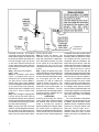
The B&M 4607646076 launch control valve must be mounted to a rigid surface to prevent vibrations that could cause failures of the joints or lines. The firewall is a good mounting location. Keep the valve and the brake lines away from the heat of the exhaust system.
B&M 4607646076 is a launch control device designed primarily for use on high-performance vehicles used in drag racing. It is intended for short-term use (60 seconds maximum) to lock the wheels while staging the vehicle for drag racing.
This device can be installed in either the front or rear wheel part of the brake system of a passenger car or light-duty truck. It should not be used as a long-term brake holding device or in place of a parking brake.
The B&M 4607646076 launch control valve must be mounted to a rigid surface to prevent vibrations that could cause failures of the joints or lines. The firewall is a good mounting location. Keep the valve and the brake lines away from the heat of the exhaust system.


-
 1
1
-
 2
2
-
 3
3
-
 4
4


B&M 4607646076 is a launch control device designed primarily for use on high-performance vehicles used in drag racing. It is intended for short-term use (60 seconds maximum) to lock the wheels while staging the vehicle for drag racing.
This device can be installed in either the front or rear wheel part of the brake system of a passenger car or light-duty truck. It should not be used as a long-term brake holding device or in place of a parking brake.
The B&M 4607646076 launch control valve must be mounted to a rigid surface to prevent vibrations that could cause failures of the joints or lines. The firewall is a good mounting location. Keep the valve and the brake lines away from the heat of the exhaust system.
Ask a question and I''ll find the answer in the document
Finding information in a document is now easier with AI
Other documents
-
Roadmaster BrakeMaster 9060 Operating instructions
-
Lotus 2004 Eleven Service Notes
-
-
Toro Workman HDX Utility Vehicle User manual
-
Ransomes 898659 User manual
-
Chevrolet TrailBlazer User manual
-
Factory Five Racing Mk4 Roadster Assembly Manual
-
 Plymouth Stratus Repair manual
-
-
 MQ Multiquip LS400 User manual

