Page is loading ...


3
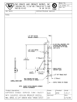
Hopper Lid
Outside Air
Knockout
(either side)
Boiler Drain
(Either Side)
Heat Exchange
Cleanout Cover
Flue Pipe - 3”
Pellet Vent
Combustion Blower
Temperature/
Pressure Gauge
Pressure Relief
Valve
Firebox Door
Control Board
Combustion Blower
Cover
Circuit Breaker
Power Cord
Heating System
Supply & Return
(either side)
Remote Zone
Control / OAT
Sensor Terminal
Firebox Draft
Test Port
Levelling Feet
Side Access
Panel
1- Controlled &
1-Un-controlled
120VAC Outlets

4
Please read this entire manual before you install and use
your new boiler. Failure to follow instructions may result in
property damage, bodily injury, or even death.
352 Mountain House Road
Halifax, PA 17032

5
Bulk Storage Hopper-
Item # 1-00-73450, with 1500 lb
pellet capacity, it will automatically
re-ll the unit hopper when it falls
below a certain level.
Inlet Cover part#
1-10-08542
Flex pipe part#
1-00-08543
(25')
Direct Vent Wall Passthrough
Item # 1-10-677077 provides for safe passing of
the 3” pellet vent pipe through an outside wall,
while providing the attachment for outside air. No
extra holes needed.
Standard method of attaching outside air. Be sure to
use the inlet cover to prevent birds and/or rodents
from entering the intake pipe. This method requires a
hole to the outside, separate from the vent passage.
Item # 2-00-232044B, secures to the boiler
and gives the support needed for the
expansion tank and circulator, while keeping
them at a workable distance from the boiler.
Item # 1-00-232200, provides
automatic ll, and converts the
heating system plumbing from
pressurized to a zero pressure
system. Allows for installation into
more places where codes and
standards restrict pressurized
systems. Circuit Board Dipswitch
#6 must be “ON” when installed.

6
Preparation For Installation:
1. Install 3/4” MPT boiler drain in the tting as shown. Either
side can be utilized. Note: If using the supply and return on
each side, either one of the returns is going to need the drain
valve incorporated.
Note: Use teon pipe thread sealant or teon tape on ALL
threads before connections are made.
2. Install the 1/2” MPT temperature/pressure gauge in tting
where shown.
3. Locate and install the outside air temperature sensor.
Location of this sensor should be on the North side of the
home or building and out of direct sunlight. Use a cat3 cable
or 18-2 thermostat wire to attach the sensor to the terminals
located beside the control board. The wires can be connected
to the sensor with wire nuts or butt splice connectors.
Boiler Kit Materials: (Refer to page 3)
List of items shipped with the unit.
1 - 3/4” Boiler Drain
1 - 3/4” Safety Relief Valve
1 - 1/2” Dual Temperature/Pressure Gauge
1 - Outdoor Air Sensor
2 - Piping Support Brackets
1 - Scraper Tool
4 - 1½” Levelling Feet. (page 7)
Attach Outside Air
Sensor Here
Bolt-Down Brackets:
Use the brackets from
the original packaging
and at least 4 bolts (not
supplied) to secure the
unit in its permanent
location.
Recommended for all
installations.
It is recommended that the
levelling feet be installed
in all installations. The air
space provided will help to
prevent condensation or
trapped moisture which may
lead to rust on the bottom of
the unit.
The feet can be adjusted
using a 7/16” open end
wrench.

7
The rst thing that needs to be done is deciding where
and how the boiler will be installed.
Things that need to be taken into consideration are the
intended use of the boiler. For example, is the boiler
going to be used as a secondary or backup heating
system? If it is to be used in conjunction with an existing
oil or gas boiler system will it be piped in parallel or
in series? The answers to these and other questions
can be determined by talking to your certied dealer
or a qualied HVAC or plumbing contractor. This will
ensure that the boiler is installed and piped to best
accommodate your needs and expectations.
Much consideration must be given to the venting. Due
to low exhaust gas temperatures, the boiler should
be placed where the venting system can be as short
as possible. Pay particular attention to electrical
connection needs and combustible/service clearance
requirements.
After the boiler is set into place the venting can be
installed.
Make sure any exhausting devices or appliances used
in the area are installed so as not to create negative
pressure in the room where the boiler is located.
This boiler must not be installed in an area or room
where chemicals or solvents are used or stored in
quantities above that of normal use.
For installations above 3000 ft. elevation,
or any installation using the atmospheric conversion,
circuit board dipswitch #6 must be in the “ON” position.
It is recommended that the levelling feet be
installed in all installations. The air space provided will
help to prevent condensation or trapped moisture which
may lead to rust on the bottom of the unit.
The feet can be adjusted using a 7/16” open end
wrench.
The striped area indicates the minimum required oor
protection area if the boiler is going to be placed on
a combustible oor. Special Note: When installing
on a protected oor, the levelling feet need to be
adjusted so that the bottom of the unit is 1¼ inches
off the oor protector (see illustration below). This
boiler requires 46⅞” X 29⅛” (48⅞ X 29⅛ in Canada)
of non combustible oor protection as shown above.
16” (US) or 18” (Canada) of the oor protection must
be in front of the boiler as shown, with 6” extending on
either side. CSA/CAN B366.1 requires oor protection
extending 2” (50mm) under horizontal section of
chimney connector. Floor protection must be a minimum
of 26 gauge sheet metal.
Minimum non-combustible oor protection area
Levelling feet must be adjusted
to give 1¼ in of clearance when
installing boiler on a protected
combustible oor.
6” [152.4mm]
16” [406.4mm]US
18”[457.2mm]CAN
29 1/8” [739.78mm]
46 7/8” [1190.63mm]US
48 7/8” [1241.43mm]CAN
NON-COMBUSTIBLE
FLOOR PROTECTION
46 7/8” [1190.63mm]US
48 7/8” [1241.43mm]CAN
29 1/8” [739.78mm]

8
Hearth & Home Technologies disclaims any responsibility for, and the warranty
and agency listing will be voided by the following actions:
• Install or operate a damaged appliance
• Modify the appliance
• Install other than as instructed by Hearth & Home Technologies
• Operate the appliance without fully assembling all components
• Overre the appliance
• Install any component or part not approved by Hearth & Home Technologies
Improper installation, adjustment, alteration, service, or maintenance can cause injury or property damage.
For assistance or additional information, consult a qualied installer, service agency or your dealer.

9
Requirements for Terminating the Venting
WARNING: Venting terminals must not be recessed
into a wall or siding.
NOTE: Only PL vent pipe wall pass-throughs and
re stops should be used when venting through com-
bustible materials.
NOTE: Always take into consideration the effect
the prevailing wind direction or other wind currents
will cause with yash and /or smoke when placing the
termination.
In addition, the following must be observed:
A. The clearance above grade must be a minimum of
18”.
1
B. The clearance to a window or door that may be
opened must be a minimum of 48” to the side, 48”
below the window/door, and 12” above the window/
door.
1
C. A 12” clearance to a permanently closed window is
recommended to prevent condensation on the window.
D. The vertical clearance to a ventilated soft located
above the terminal within a horizontal distance of 2 feet
(60 cm) from the center-line of the terminal must be a
minimum of 18”.
E. The clearance to an unventilated soft must be a
minimum of 12”.
F. The clearance to an outside corner is 11” from center
of pipe.
G. The clearance to an inside corner is 12”. If you see
deposits developing on the wall, you may need to extend
this distance to accomodate your installation conditions.
H. A vent must not be installed within 3 feet (90 cm)
above a gas meter/regulator assembly when measured
from the horizontal center-line of the regulator.
1
I. The clearance to service regulator vent outlet must be
a minimum of 6 feet.
1
J. The clearance to a non-mechanical air supply inlet
to the building or the combustion air inlet to any other
appliance must be a minimum of 48”.
1
K. The clearance to a mechanical air supply inlet must
be a minimum of 10 feet.
1
L. The clearance above a paved sidewalk or a paved
driveway located on public property must be a minimum
of 7 feet.
1,2
M. The clearance under a veranda, porch, deck or
balcony must be a minimum of 12 inches.
1,3
(See B. also)
NOTE: The clearance to vegetation and other exte-
rior combustibles such as mulch is 36” as measured from
the center of the outlet or cap. This 36” radius continues
to grade or a minimum of 7 feet below the outlet.
1
Certain Canadian and or Local codes or regulations
may require different clearances.
2
A vent shall not terminate directly above a sidewalk
or paved driveway which is located between two
single family dwellings and serves both dwellings.
3
Only permitted if veranda, porch, deck, or balcony is
fully open on a minimum of 2 sides beneath the oor.
= Vent terminal
= Air supply inlet
= Area where terminal is not permitted
Fig. 2
NOTE: Where passage through a wall, or partition of
combustible construction is desired, the installation
shall conform to CAN/CSA-B365. (if in Canada)

10
Venting
Use only 3” pellet vent pipe to vent your pellet boiler.
A combustion blower is used to extract the combustion
gases from the rebox. This creates a negative pressure in
the rebox and a positive pressure in the venting system as
shown in Fig. 4. The longer the vent pipe and more elbows
used in the system, the greater the ow resistance, and the
greater the chance for creosote accumulation. Because of
these facts we recommend using as few elbows as possible
and 18 feet or less of vent pipe. The maximum horizontal
run should never exceed 8 feet.
Be sure to use wall and ceiling pass through ttings
(which are approved for pellet vent pipe ) when going
through combustible materials. Be sure to use a starting
collar to attach the venting system to the stove. The starting
collar must be sealed to the stove ue collar with high
temp silicone caulking or aluminum tape, and screwed
into the units’ ue collar in a minimum of three (3) places.
Due to low exhaust temperatures, increasing the diameter
of the venting or exceeding the recommendations of the
venting graph, is strongly discouraged.
Vent Pipe
3” pellet vent pipe (also known as “PL” vent) is constructed
of two layers with air space between the layers. This air space
acts as an insulator and reduces the outside surface temperature
to allow a minimum clearance to combustibles as low as 1
inch. In Canada the minimum clearance to combustibles is
3 inches. Check with the venting manufacturer to be certain
of specied clearances.
The sections of pipe lock together to form an air tight seal
in most cases; however, in some cases a perfect seal is not
achieved. For this reason and the fact that the unit operates
with a positive vent pressure, we specify that all joints
within the structure should be secured with at least 3
screws, and sealed with silicone caulking.
Fig. 3
Creosote - Formation and Need for Removal - When wood is burned slowly, it produces tar and other organic vapors,
which combine with expelled moisture to form creosote. The creosote vapors condense in the relatively cool chimney ue
of a slow-burning re. As a result, creosote residue accumulates on the ue lining. When ignited, this creosote makes an
extremely hot re. The pellet vent pipe should be inspected at least twice monthly during the heating season to determine
if a creosote buildup has occurred. If creosote has accumulated it should be removed to reduce the risk of a chimney re.
Guidance on minimizing creosote formation and the need for periodic creosote removal: The chimney should be inspected
during the heating season to determine if a creosote build-up has occurred. If a signicant layer of creosote has accumulated,
1/8” (3mm) or more, it should be removed to reduce the risk of a chimney re.
NOTE:Use only 3” diameter Pellet venting system.
Be sure to inspect and clean exhaust venting system
frequently.
10
Total Lineal Feet Combined
Should Not Exceed 18' as
measured from the outlet.
0
2
6
4
8
68 4 2
5
Altitude in Thousands of Feet
10
Maximum Horizontal Run 8'
10
5
7
6
9
8
18
15
4
The Total Lineal Feet
Decreases as the
Altitude Increases
Fig. 4
-
+

11
3” Type “L” or
“PL” Vent pipe
The minimum vent conguration is a 90
o
or Tee on a starter
collar and a 24” length horizontal through an exterior wall.
A cap on the end should direct the ue gases down and away
from the structure. See Fig. 5.
The maximum horizontal length is 8 feet. The minimum
termination height above the exterior grade is 18”. The
maximum total length of any conguration is 18 feet*.
* (see venting graph on page 10 for exceptions)
NOTE: Cleanout Tee’s should always be used on the
transitions to horizontal pipe to allow easy access for
cleaning.
The venting graph allows for one(1) 90 deg. or Tee tting
in any conguration.
If more 90’s, T’s, or 45’s are needed the total length must
be adjusted to allow for the added restriction.
Up to four (4) additional 90’s, Tee’s, or equivalent 45’s
can be added as long as the overall length is adjusted in
accordance with the values listed below. (See the venting
graph on page 10.)
Each Vertical ---- 90 deg. or T subtract 2.5 feet
Each Vertical ---- 45 deg. subtract 1.5 feet
Each Horizontal - 90 deg. or T subtract 5.0 feet
Each Horizontal - 45 deg. subtract 2.5 feet
Venting Into An Existing Chimney
The boiler may be vented into an existing masonry or Class
A metal chimney, providing that the chimney is less than 20
feet above the connector. A ue liner, no more than 4-inch
diameter, must be installed, along with a termination cap and
the proper ashing to seal the existing ue.
The venting Can Not be installed in a chimney serving
another appliance.
The chimney should be cleaned and/or inspected before
installation of the vent liner.
Due to low exhaust temperatures, and the increased
possibility of condensation and creosote formation, additional
measures may need taken to increase the ue temperature.
One such measure would be to remove the two rear-most
spiral bafes, above the burn pot, from their heat exchange
tubes. Although some efciency will be lost, an increased
ue temperature will result.
The flue liner should be inspected frequently, during
operation, to monitor its performance and cleanliness.
Venting
This is the minimum venting conguration. NOTE: A starting
collar is needed in order to remove the units’ cleanout cover.
Fig. 5
Any exterior venting (vent pipe exposed to outside
ambiant temperatures) should be kept to a
minimum, due to potential condensation problems.
This is especially important in high humidity-cold
weather climates, such as maritime areas, lake shores,
and low river valleys.
Other examples of possible installations of the venting.
NOTE: Use only 3” diameterPellet venting system.
Be sure to inspect and clean exhaust venting system
frequently.

12
NOTE: Read and follow all of the vent pipe
manufacturers’ instructions on the proper installation
and support of the vent pipe. Adhere to all clearances
to combustibles.
DO NOT INSTALL A FLUE DAMPER IN THE
EXHAUST VENTING SYSTEM OF THIS UNIT.
DO NOT CONNECT THIS UNIT TO A CHIMNEY
FLUE SERVING ANOTHER APPLIANCE.
INSTALL VENT WALL PASS-THROUGHS AT
CLEARANCES SPECIFIED BY THE VENT
MANUFACTURER.
INSTALLATION IS TO BE PERFORMED BY A
QUALIFIED INSTALLER.
KEEP COMBUSTIBLE MATERIALS SUCH
AS GRASS, LEAVES, ETC. AT LEAST 3 FEET
AWAY FROM THE POINT DIRECTLY UNDER
THE VENT TERMINATION. (BETWEEN THE
VENT AND THE GROUND)
WARNING
KEEP COMBUSTIBLES AWAY
FROM FLUE OUTLET.
CAUTION
INSTALLATION IS TO BE PERFORMED BY
A QUALIFIED INSTALLER.
NOTE: All installation clearances and restrictions
must be adhered to.
To reduce probability of reverse drafting during
a power failure, Hearth & Home Technologies
strongly recommends:
•Installing the pellet vent with a minimum vertical rise
of ve feet. Preferably terminating above the roof line.
•Installing an outside air connection to the appliance.
To prevent soot damage to exterior walls, and to
prevent re-entry of soot or ash into the home:
•Maintain specied clearances to windows, doors and
air inlets, including air conditioners.
•Vents should not be placed below ventillated softs.
•Avoid venting into alcove locations.
•Vents should not terminate under overhangs, decks or
onto covered porches.
•Maintain minimum clearance of 12” from the vent
termination to the exterior wall.
Hearth & Home Technologies assumes no
responsibility for, nor does the warranty extend to,
smoke damage caused by reverse drafting of pellet
appliances under power failure conditions.

13
NOTE: If outside air is installed, the inlet cover should not
be placed in an area where drifting of snow or ice will build
up, blocking the intake air supply.
Hearth & Home Technologies strongly recommends the use
of outside air for all pellet boiler applications.
Per national building codes, consideration must be given
to combustion air supply for all appliances in the vicinity
of the pellet boiler. Failure to supply adequate combustion
air for all appliance demands may lead to backdrafting of
those appliances. Consult with your HVAC Professional to
determine that all combustion air requirements are met.
When the appliance is side-wall vented: The air intake is
best located on the same exterior wall as, and lower than the
exhaust vent outlet.
When the appliance is roof vented: The air intake is best
located on the exterior wall oriented towards the prevailing
wind direction, during the heating season.
The Outside Air Intake Pipe is inside the Rear Cover and to
the right of the feeder motor. The ex pipe is made to slide
inside the Air Intake Pipe. See Fig. 8. It should be held into
place with silicone, foil tape, or a hose clamp. (not supplied)
Negative Pressure and Electrical Power Failure
To reduce the probability of back-drafting or burn-back in the
pellet appliance during a power failure, the appliance must
be able to draft naturally without exhaust blower operation.
Negative pressure in the house will resist this natural draft if
not accounted for in the pellet appliance installation.
Heat rises in the house and leaks out at upper levels. This air
must be replaced with cold air from outdoors which ows into
lower levels of the house. Vents and chimneys into basements
and lower levels can become the conduit for air supply and
reverse under these conditions.
The outside air supply will supply most of the demands of
the pellet appliance to resist back-drafting, but consideration
must be given to the total house demand. It may be necessary
to add additional ventilation to the space in which the pellet
appliance is located. Consult with your HVAC professional
to determine the ventilation demands for your house.
Inlet Cover part#
1-10-08542
Fig. 6
Fig. 7
Rear Cover
Outside Air Pipe
Knockout
Feeder Cover
Side Cover
Fig. 8
Outside Air Inlet Pipe
Outside Air
Although strongly recommended, the use of outside
air is optional, except where required by local building
codes. To install outside air, use metal ex pipe, part
# 1-00-08543 (25’ roll) See Fig. 6. There is a break-
away hole on either rear panel which must be removed
before connecting the ex pipe. See Fig. 7. The pipe
should be run outside and terminate 3 feet or more
below or 1 foot or more to the side of the vent pipe
outlet. Never terminate the outside air above the vent
pipe outlet. The maximum length of this pipe is 15
feet. Inlet cover part number 1-10-08542 should be
used to keep birds, rodents etc.out of the inlet pipe.
See Fig.6.

14
BYPASS
VALVE
SYSTEM SUPPLY 3/4"
* 3/4" NPT MALE
PLUG
* BOILER DRAIN,
3/4" NPT MALE X
3/4" HOSE
TYPICAL BOILER HOT WATER PIPING SHOWING AIR REMOVAL SYSTEM, PROVISIONS FOR THE
EXPANSION OF WATER AND THE AUTOMATIC COLD WATER SUPPLY. ALSO SHOWN BUT NOT
NECESSARILY NEEDED IS THE BOILER BYPASS LINE. THE NECESSITY OF THIS LINE WILL BE
DETERMINED BY THE INSTALLING CERTIFIED PLUMBER OR HVAC CONTRACTOR.
SHUT-OFF
VALVE
* AUTOMATIC AIR VENT
PIPE TO WITHIN
6" OF THE FLOOR
OR A FLOOR
DRAIN
UNION
* PRESSURE RELIEF VALVE
* TEMP/PRESSURE
GAUGE
SHUT-OFF VALVE
UNION
SHUT-OFF
VALVE
NOTE: ALWAYS REFER TO THE INDIVIDUAL COMPONENTS
RECOMMENDED INSTALLATION INSTRUCTIONS FOR THE PROPER
MOUNTING POSITION AND LOCATION WITHIN THE PIPING SYSTEM.
** THERMOMETER
PRESSURE REDUCING
VALVE (PRV) OR
COMBINATION PRV AND
RELIEF VALVE
EXPANSION TANK
(DIAPHRAGM TYPE)
SYSTEM RETURN 3/4"
3/4" BOILER
BYPASS LINE (IF
REQUIRED)
* ITEMS SUPPLIED
** OPTIONAL
CHECK VALVE (OR
BACKFLOW
PREVENTER IF
REQUIRED)
** THERMOMETER
AIR VENT
AIR SCOOP
SYSTEM SUPPLY 3/4"
COLD
WATER
SUPPLY 1/2"
NOTICE: When installing with the Atmospheric Conversion, all of the pressurized system
components shown are not necessary. Air vents or bleeders should be removed from the
plumbing system to prevent air from entering the lines. Control dipswitch #6 must be “ON”.
NOTE: Cold return water temperature (Sustained temperatures below 140 degrees
Fahrenheit) will lead to condensation or moisture in the firebox. This moisture can
lead to creosote formation. To help minimize moisture and creosote, it is strongly
recommended that some method of temperature balance is incorporated into the
return system.
EXAMPLE OF A TYPICAL MULTI-ZONE HEATING SYSTEM WITH BOILER BYPASS AND INDIRECT
DOMESTIC HOT WATER ZONE
SHUT-OFF VALVE
* 3/4" NPT MALE PLUG
* BOILER DRAIN, 3/4" NPT MALE X
3/4" HOSE
PIPE TO WITHIN 6" OF THE FLOOR OR A
FLOOR DRAIN
UNION
* AUTOMATIC AIR VENT
SYSTEM SUPPLY 3/4"
* TEMP/PRESSURE
GAUGE
* PRESSURE RELIEF VALVE
SHUT-OFF VALVE
UNION
DOMESTIC HOT
WATER STORAGE
HEATER WITH
INTERNAL HEAT
EXCHANGER
RETURN WATER
CHECK VALVE
OUT
IN
** THERMOMETER
SYSTEM RETURN 3/4"
** OPTIONAL
* ITEMS SUPPLIED
BOILER BYPASS CAN ALSO BE DONE WITH A 3-WAY
MIXING VALVE AND CAN BE CONTROLLED MANUALLY
OR WITH AN AUTOMATIC ACTUATING MOTOR. IF SO,
THE TWO BALANCING VALVES ARE NOT NEEDED
NOTE: ALWAYS REFER TO THE INDIVIDUAL COMPONENTS
RECOMMENDED INSTALLATION INSTRUCTIONS FOR THE PROPER
MOUNTING POSITION AND LOCATION WITHIN THE PIPING SYSTEM.
BALANCING VALVE
CHECK VALVE
EXPANSION TANK, AIR REMOVAL AND COLD WATER SUPPLY
CIRCULATOR
HOT
COLD
** THERMOMETER
SYSTEM SUPPLY 3/4"
BYPASS (BALANCING) VALVE
BOILER WATER
SUPPLY WATER
NOTICE: When installing with the Atmospheric Conversion, all of the pressurized
system components shown are not necessary. Air vents or bleeders should be
removed from the plumbing system to prevent air from entering the lines.
Control dipswitch #6 must be “ON”.
NOTE: Cold return water temperature (Sustained temperatures below 140 degrees
Fahrenheit) will lead to condensation or moisture in the firebox. This moisture can
lead to creosote formation. To help minimize moisture and creosote, it is strongly
recommended that some method of temperature balance is incorporated into the
return system.

15
Boilers intended to be connected to an existing boiler or boiler system shall:
1. Be capable of being installed without interfering with the normal delivery of heated water from the original boiler to the
radiation system.
2. Be capable of being installed to operate as intended without affecting the operation of the electrical and mechanical safety
controls of the original boiler.
3. Provide, upon completion of the installation, for a change over from one fuel to the other without requiring the manual
adjustment of any controls or components other than the thermostats.
4. Be compatible with the operation of a service water-heating coil within the original boiler without bypassing the operation
of the solid-fuel boiler.
5. Have provision for preventing, or adequate water capacity within the boiler to prevent, damage to the boiler from loss of
circulation due to electrical power failure.
6. Be capable of being installed without changing the function of the control or rewiring of the original boiler. A wiring
interconnection is permitted. The electrical system of both boilers shall be powered from a single branch circuit without
exception.
(CAN/CSA-B366.1-M91)
7. Pertaining to CAN/CSA- B365-01, Have a clearly labelled device, located at each entrance to the boiler area, which can
be thrown to discontinue operation to the feed system.
EXAMPLE OF PIPING WITH AN INDEPENDENT CIRCULATOR SYSTEM
CONNECTED TO AN EXISTING OPERATIONAL BOILER
* BOILER DRAIN, 3/4" NPT MALE X 3/4" HOSE
* 3/4" NPT MALE PLUG
RETURN 3/4"
SYSTEM SUPPLY
* AUTOMATIC AIR VENT
* TEMP/PRESSURE
GAUGE
* PRESSURE RELIEF VALVE
PIPE TO WITHIN
6" OF THE
FLOOR OR A
FLOOR DRAIN
UNION
OUT
UNION
SHUT-OFF VALVE
EXISTING
BOILER
UNION
NOTE: NOT SHOWN IN THIS DRAWING ARE ALL OF THE
ASSOCIATED PIPING AND CONTROLS THAT SHOULD
ALREADY BE IN PLACE WITH THE EXISTING BOILER
SYSTEM. FOR EXAMPLE, THE EXPANSION TANK, THE
COLD WATER SUPPLY , AIR REMOVAL SYSTEM ETC... IT IS
EXTREMELY IMPORTANT THAT THIS BOILER BE
INSTALLED BY A QUALIFIED INSTALLER AND THAT ALL
EXISTING CONTROLS AND SAFETY DEVICES ARE
VERIFIED AS OPERATIONAL.
* ITEMS SUPPLIED
NOTE: ALWAYS REFER TO THE INDIVIDUAL COMPONENTS
RECOMMENDED INSTALLATION INSTRUCTIONS FOR THE PROPER
MOUNTING POSITION AND LOCATION WITHIN THE PIPING SYSTEM.
CIRCULATOR
SHUT-OFF
VALVE
SHUT-OFF
VALVE
UNION
SUPPLY 3/4"
SYSTEM RETURN
UNION
IN
BALANCING VALVE
SHUT-OFF VALVE
UNION
CIRCULATOR
NOTICE: When installing with the Atmospheric Conversion, all of the
pressurized system components shown are not necessary. Air vents or
bleeders should be removed from the plumbing system to prevent air
from entering the lines. Control dipswitch #6 must be “ON”.
NOTE: Cold return water temperature (Sustained temperatures below 140 degrees
Fahrenheit) will lead to condensation or moisture in the firebox. This moisture can
lead to creosote formation. To help minimize moisture and creosote, it is strongly
recommended that some method of temperature balance is incorporated into the
return system.
Anti-freeze and/or boiler water treatment:
There is no restriction on the type of commercial antifreeze used. When lling the boiler water system, it is recommended
that some form of boiler water treatment be used.

16
Installing Duct
EXAMPLE OF PIPING IN SERIES WITH
AN EXISTING OPERATIONAL BOILER
* BOILER DRAIN, 3/4" NPT MALE X 3/4" HOSE
* 3/4" NPT MALE PLUG
* TEMP/PRESSURE
GAUGE
PIPE TO WITHIN 6" OF THE FLOOR OR A
FLOOR DRAIN
* PRESSURE RELIEF VALVE
UNION
SHUT-OFF VALVE
UNION
* AUTOMATIC AIR VENT
NOTE: NOT SHOWN IN THIS DRAWING ARE ALL OF THE
ASSOCIATED PIPING AND CONTROLS THAT SHOULD
ALREADY BE IN PLACE WITH THE EXISTING BOILER SYSTEM.
FOR EXAMPLE, THE EXPANSION TANK, THE COLD WATER
SUPPLY , AIR REMOVAL SYSTEM ETC... IT IS EXTREMELY
IMPORTANT THAT THIS BOILER BE INSTALLED BY A
QUALIFIED INSTALLER AND THAT ALL EXISTING CONTROLS
AND SAFETY DEVICES ARE VERIFIED AS OPERATIONAL.
NOTE: ALWAYS REFER TO THE INDIVIDUAL COMPONENTS RECOMMENDED
INSTALLATION INSTRUCTIONS FOR THE PROPER MOUNTING POSITION AND
LOCATION WITHIN THE PIPING SYSTEM.
* ITEMS SUPPLIED
SYSTEM RETURN 3/4"
EXISTING BOILER
SHUT-OFF VALVE
SYSTEM SUPPLY 3/4"
OUT
IN
NOTICE: When installing with the Atmospheric Conversion, all of the pressurized
system components shown are not necessary. Air vents or bleeders should be
removed from the plumbing system to prevent air from entering the lines.
Control dipswitch #6 must be “ON”.
NOTE: Cold return water temperature (Sustained temperatures below 140 degrees
Fahrenheit) will lead to condensation or moisture in the firebox. This moisture can
lead to creosote formation. To help minimize moisture and creosote, it is strongly
recommended that some method of temperature balance is incorporated into the
return system.
EXAMPLE OF PIPING IN PARALLEL WITH
AN EXISTING OPERATIONAL BOILER
* BOILER DRAIN, 3/4" NPT MALE
X 3/4" HOSE
* 3/4" NPT MALE PLUG
SYSTEM RETURN 3/4"
SYSTEM SUPPLY 3/4"
* AUTOMATIC AIR VENT
* TEMP/PRESSURE
GAUGE
* PRESSURE RELIEF VALVE
PIPE TO WITHIN
6" OF THE
FLOOR OR A
FLOOR DRAIN
UNION
IN
UNION
SHUT-OFF VALVE
SHUT-OFF
VALVE
EXISTING
BOILER
BALANCING
VALVE
UNION
BALANCING
VALVE
UNION
OUT
NOTE: NOT SHOWN IN THIS DRAWING ARE ALL OF THE
ASSOCIATED PIPING AND CONTROLS THAT SHOULD
ALREADY BE IN PLACE WITH THE EXISTING BOILER
SYSTEM. FOR EXAMPLE, THE EXPANSION TANK, THE
COLD WATER SUPPLY , AIR REMOVAL SYSTEM ETC... IT IS
EXTREMELY IMPORTANT THAT THIS BOILER BE
INSTALLED BY A QUALIFIED INSTALLER AND THAT ALL
EXISTING CONTROLS AND SAFETY DEVICES ARE
VERIFIED AS OPERATIONAL.
* ITEMS SUPPLIED
NOTE: ALWAYS REFER TO THE INDIVIDUAL COMPONENTS
RECOMMENDED INSTALLATION INSTRUCTIONS FOR THE PROPER
MOUNTING POSITION AND LOCATION WITHIN THE PIPING SYSTEM.
NOTICE: When installing with the Atmospheric Conversion, all of
the pressurized system components shown are not necessary.
Air vents or bleeders should be removed from the plumbing
system to prevent air from entering the lines. Control dipswitch
#6 must be “ON”.
NOTE: Cold return water temperature (Sustained temperatures below 140 degrees
Fahrenheit) will lead to condensation or moisture in the firebox. This moisture can
lead to creosote formation. To help minimize moisture and creosote, it is strongly
recommended that some method of temperature balance is incorporated into the
return system.

17
Installing Duct/Air Conditioning
PRESSURE REDUCING VALVE
(PRV) OR COMBINATION PRV
AND RELIEF VALVE
* BOILER DRAIN, 3/4" NPT
MALE X 3/4" HOSE
* 3/4" NPT MALE PLUG
PIPE TO WITHIN 6" OF THE
FLOOR OR A FLOOR DRAIN
UNION
SENSING BULB
SHUT-OFF VALVE
* ITEMS SUPPLIED
** OPTIONAL
** THERMOMETER
SYSTEM RETURN 3/4"
TYPICAL BOILER HOT WATER PIPING SHOWING AIR REMOVAL SYSTEM, PROVISIONS FOR THE
EXPANSION OF WATER AND THE AUTOMATIC COLD WATER SUPPLY. ALSO SHOWN IS THE AUTOMATIC
MIXING VALVE. THIS COULD ALSO BE DONE BY (2) CLOSELY SPACED TEE'S. THE PROPER PIPING FOR THE
INTENDED USE WILL BE DETERMINED BY THE INSTALLING CERTIFIED PLUMBER OR HVAC CONTRACTOR.
* AUTOMATIC AIR VENT
* TEMP/PRESSURE
GAUGE
* PRESSURE
RELIEF VALVE
EXPANSION TANK
(DIAPHRAGM TYPE)
SHUT-OFF
VALVE
UNION
AIR VENT
AIR SCOOP
** THERMOMETER
SYSTEM SUPPLY 3/4"
NOTE: ALWAYS REFER TO THE INDIVIDUAL COMPONENTS
RECOMMENDED INSTALLATION INSTRUCTIONS FOR THE PROPER
MOUNTING POSITION AND LOCATION WITHIN THE PIPING SYSTEM.
CHECK VALVE (OR BACKFLOW
PREVENTER IF REQUIRED)
AUTOMATIC
MIXING VALVE
SHUT-OFF VALVE
COLD WATER
SUPPLY 1/2"
NOTICE: When installing with the Atmospheric Conversion, all of the
pressurized system components shown are not necessary. Air vents or
bleeders should be removed from the plumbing system to prevent air
from entering the lines. Control dipswitch #6 must be “ON”.
NOTE: Cold return water temperature (Sustained temperatures below 140 degrees
Fahrenheit) will lead to condensation or moisture in the firebox. This moisture can
lead to creosote formation. To help minimize moisture and creosote, it is strongly
recommended that some method of temperature balance is incorporated into the
return system.
EXAMPLE OF TYPICAL TANKLESS DOMESTIC HOT WATER PIPING
MIXING VALVE
SAFETY RELIEF VALVE
FLOW REGULATOR WILL NEED TO MATCH THE GPM RATING OF THE DOMESTIC COIL.
CUSTOMER SUPPLIED SS
PLATE HEAT EXCHANGER
DOMESTIC WATER
OUTLET
DOMESTIC WATER
INLET
SHUT-OFF VALVE
SHUT-OFF VALVE
OUTLET
INLET
HOSE BIB
HOSE BIB TO BACKFLUSH COIL IF NEEDED
FLOW REGULATOR
HIGH TEMPERATURE WATER
( IF NEEDED )
NOTE: ALWAYS REFER TO THE INDIVIDUAL COMPONENTS
RECOMMENDED INSTALLATION INSTRUCTIONS FOR THE PROPER
MOUNTING POSITION AND LOCATION WITHIN THE PIPING
SYSTEM.
COLD WATER SUPPLY
MIXING VALVE SET TO DESIRED WATER TEMPERATURE.
NORMALLY NOT MORE THAN 120 DEGREES.
ISOLATION VALVE
TEMPERED HOT WATER TO
SHOWERS AND FAUCETS

18
NOTE: ALWAYS REFER TO THE INDIVIDUAL COMPONENTS RECOMMENDED
INSTALLATION INSTRUCTIONS FOR THE PROPER MOUNTING POSITION AND
LOCATION WITHIN THE PIPING SYSTEM.
MIXING VALVE SET TO DESIRED WATER TEMPERATURE.
NORMALLY NOT MORE THAN 120 DEGREES.
TEMPERED HOT WATER FOR
SHOWERS AND FAUCETS
FROM BOILER
CIRCULATOR
TO BOILER
EXAMPLES OF TYPICAL DOMESTIC HOT WATER STORAGE PIPING
EXAMPLE #1
TO BOILER
CIRCULATOR
FROM BOILER
COLD
HOT
IN
OUT
EXAMPLE #2
MIXING VALVE
COLD
DOMESTIC HOT
WATER
STORAGE
HEATER WITH
INTERNAL HEAT
EXCHANGER
HOT
IN
OUT
HIGHER
TEMPERATURE
WATER (IF NEEDED)
CAUTION: No domestic water
temperature
regulation shown
CAUTION: No domestic water
temperature
regulation shown
DOMESTIC HOT
WATER STORAGE
HEATER WITH
INTERNAL HEAT
EXCHANGER
EXAMPLE OF A TYPICAL MULTI-ZONE HEATING SYSTEM WITH A SINGLE
CIRCULATOR AND INDIVIDUAL ZONE VALVES
NOTE: ALWAYS REFER TO THE INDIVIDUAL COMPONENTS RECOMMENDED
INSTALLATION INSTRUCTIONS FOR THE PROPER MOUNTING POSITION AND
LOCATION WITHIN THE PIPING SYSTEM.
AIR VENT
SYSTEM RETURN 3/4"
TO BOILER
FROM ADDITIONAL ZONES
SHUT-OFF VALVE
UNION
AIR VENT (TYPICALLY
INSTALLED IN THE HIGHEST
ACCESSABLE LOCATION IN
THE PIPING)
ZONE 1
ZONE 2
ZONE 3
FROM BOILER
SYSTEM SUPPLY 3/4"
CIRCULATOR
ZONE 2
ZONE 1
TO ADDITIONAL ZONES
UNION
ZONE VALVE
BALANCING
VALVE
ZONE 3
NOTICE: When installing with the Atmospheric Conversion, all
of the pressurized system components shown are not
necessary. Air vents or bleeders should be removed from the
plumbing system to prevent air from entering the lines. Control
dipswitch #6 must be “ON”.
NOTE: Cold return water temperature (Sustained temperatures below
140 degrees Fahrenheit) will lead to condensation or moisture in the
firebox. This moisture can lead to creosote formation. To help minimize
moisture and creosote, it is strongly recommended that some method
of temperature balance is incorporated into the return system.

19
AIR VENT (TYPICALLY
INSTALLED IN THE HIGHEST
ACCESSABLE LOCATION IN
THE PIPING)
(LOW TEMPERATURE) RADIANT FLOOR HEAT
(LOW TEMPERATURE) RADIANT FLOOR HEAT
FROM BOILER
SYSTEM SUPPLY 3/4"
SYSTEM RETURN 3/4"
HOT
THERMOSTATIC
MIXING VALVE
TO BOILER
COLD
MIX
UNION
SHUT-OFF VALVE
NOTE: IF CIRCULATOR DOES NOT HAVE
CHECK VALVE THEN A FLOW CONTOL
VALVE WILL ALSO BE NEEDED AND
INSTALLED IN THIS LOCATION
EXAMPLE OF A COMBINATION HIGH/LOW MULTI-ZONE HEATING SYSTEM
WITH INDIVIDUAL ZONE CIRCULATORS
CIRCULATORS WITH INTEGRAL
CHECK VALVE (SEE NOTE)
SHUT-OFF VALVE
(HIGH TEMPERATURE) BASEBOARD HEAT
ZONE 1
ZONE 2
ZONE 3
AIR VENT
ZONE 1
NOTE: ALWAYS REFER TO THE INDIVIDUAL COMPONENTS RECOMMENDED
INSTALLATION INSTRUCTIONS FOR THE PROPER MOUNTING POSITION AND
LOCATION WITHIN THE PIPING SYSTEM.
ZONE 2
ZONE 3
NOTICE: When installing with the
Atmospheric Conversion, all of the
pressurized system components
shown are not necessary. Air vents or
bleeders should be removed from the
plumbing system to prevent air from
entering the lines. Control dipswitch
#6 must be “ON”.
NOTE: Cold return water temperature (Sustained temperatures below 140 degrees
Fahrenheit) will lead to condensation or moisture in the firebox. This moisture can lead to
creosote formation. To help minimize moisture and creosote, it is strongly recommended
that some method of temperature balance is incorporated into the return system.
EXISTING
GAS / OIL
FURNACE
OR
ELECTRIC
HEAT
PUMP
NOTE: NEVER INSTALL HOT WATER
COIL ON THE RETURN SIDE
OF THE HEATING SYSTEM
* ITEMS SUPPLIED
PRESSURE REDUCING VALVE
(PRV) OR COMBINATION
PRV AND RELIEF VALVE
* BOILER DRAIN,
3/4" NPT MALE X
3/4" HOSE
* 3/4" NPT MALE PLUG
PIPE TO
WITHIN 6" OF
THE FLOOR
OR A FLOOR
DRAIN
UNION
COLD
WATER
SUPPLY 1/2"
SHUT-OFF VALVE
CHECK VALVE (OR BACKFLOW
PREVENTER IF REQUIRED)
SHUT-OFF VALVE
CIRCULATOR
RETURN
AIR FLOW
SYSTEM RETURN 3/4"
HOT WATER
HEATING COIL
TO BE SIZED
BY INSTALLER
EXAMPLE OF A TYPICAL FORCED HOT AIR HEATING SYSTEM
WITH THE BOILER DIRECT TO AN IN DUCT HOT WATER COIL
NOTE: ALWAYS REFER TO THE INDIVIDUAL COMPONENTS
RECOMMENDED INSTALLATION INSTRUCTIONS FOR THE
PROPER MOUNTING POSITION AND LOCATION WITHIN THE
PIPING SYSTEM.
* AUTOMATIC AIR VENT
* PRESSURE RELIEF VALVE
* TEMP/PRESSURE
GAUGE
SYSTEM SUPPLY 3/4"
AIR VENT
AIR FLOW
AIR FLOW
UNION
SHUT-OFF
VALVE
EXPANSION TANK
(DIAPHRAGM TYPE)
FLOW CHECK
PURGE & BALANCE
VALVE
(SIZED FOR TOTAL
SYSTEM VOLUME)
NOTICE: When installing with the Atmospheric Conversion, all of the
pressurized system components shown are not necessary. Air vents
or bleeders should be removed from the plumbing system to prevent
air from entering the lines. Control dipswitch #6 must be “ON”.
NOTE: Cold return water temperature (Sustained temperatures below 140 degrees Fahrenheit)
will lead to condensation or moisture in the firebox. This moisture can lead to creosote
formation. To help minimize moisture and creosote, it is strongly recommended that some
method of temperature balance is incorporated into the return system.

20
Electrical interconnection of the BH60 to an existing heat pump, or fuel-red hot air furnace:
Interconnection with a heat pump will generally require a second thermostat to be installed. It is recommended
that a new electronic thermostat be installed as close to the existing thermostat as possible. Installing within one
foot of the existing thermostat is recommended for ease of interconnection and similar temperature sensing ability.
If programmability is desired, both thermostats should have this capability. If only the new thermostat is
programmable, you’ll need to keep the existing thermostat set several degrees below the lowest programmed
temperature setting of the new thermostat. NOTE: In this conguration, if the BH60 cannot maintain the desired
thermostat setting, the room will be allowed to cool to the lower set point of the existing thermostat before allowing
the heat pump to operate.
Special note: Even if the heat pump has a multi-stage thermostat, it cannot be re-wired to make the rst stage control
the BH60, and the second stage control the heat pump. All multi-stage heat pump thermostats are interconnected
so that the compressor unit and/or the changeover solenoid activate with the rst stage only.
Controlling the existing furnace fan during overheat situation.
Following the wiring diagram on the next page, you will need to supply and install a piece of 18/3 Thermostat
wire between the low-voltage control terminal strip on the upper left-hand side of the BH60’s control cover, to the
low-voltage control of the existing furnace.
Note: Some systems may have external terminals and some may have them enclosed within the unit. If the
connections to the exisitng system need to be made internally, be sure to use the proper protective grommet
or connector where passing through the cabinet of the existing unit.
If the wiring used does not match the colorings listed, follow the corresponding numbers on the terminal strips
to ensure proper connection.
Step 1. Disconnect electrical power to the existing heating system.
Step 2. Install the above mentioned thermostat wire between the two systems
Step 3. Connect the three (3) wires to the BH60 control terminal strip as indicated.
Step 4. Remove the green wire which comes from the exisiting thermostat and connects to the terminal marked
“G” on the existing system and splice it to the green (or #1) wire from the BH60.
Step 5. Connect the white wire (or #5) from the BH60 to the “G” terminal of the existing system. This white wire
should be the only wire connected to “G”.
Step 6. Now, the red (#3) wire from the BH60 should be added to the “R” terminal of the existing system. Do not
remove or replace any existing wires from “R”, just add this one to them.
Restore power to the existing system only. Using the existing thermostat, increase the setting to verify that the
system works as it did prior to the interconnection. Increase and decrease the thermostat a few times to verify
proper reaction. In the case of a heat pump system, be sure the outdoor compressor unit is also cycling. Notice:
Most compressors have a built in lockout timer (usually 5 minutes) so you may need to wait between thermostat
adjustments to verify proper operation.
Once you are certain that nothing changed with the operation of the existing system, turn the existing system’s
thermostat down far enough that it won’t come on during the test. Connect power to the BH60, and turn on the
circuit breaker on the front of the unit. With the control in the “OFF” position, turn the feed adjuster knob to “Test”.
When the OVERHEAT SAFETY ZONE light illuminates, the fan on the existing system should come on. Be sure
that the fan is the only thing on. There should be no power to the compressor or the oil or gas burner.
/