Sherwood RD-6108 Owner's manual
- Category
- AV receivers
- Type
- Owner's manual

OWNERS MANUAL

RD-6108(A) 2003.3.4 3:53 FM _4101X12
Introduction
UNPACKING AND i
Congratulations on Your Purchase!
Your new high fidelity receiver is designed to deliver
maximum enjoyment and years of trouble free service.
Please take a few moments to read this manual
thoroughly. It will explain the features and operation of
your unit and help ensure a trouble free installation.
Please unpack your unit carefully. We recommend that
you save the carton and packing material. They will be
helpful if you ever need to move your unit and may be
required if you ever need to return it for service. Your unit
is designed to be placed in a horizontal position and it is
important to allow at least two inches of space behind
your unit for adequate ventilation and cabling
convenience.
To avoid damage, never place the unit near radiators, in
front of heating vents, in direct sunlight, or in excessively
humid or dusty locations. Connect your complementary
components as illustrated in the following section.
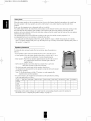
,_ RISK OF ELECTRIC SHOCK
DO NOT OPEN
CAUTION : TO REDUCE THE RISK OF
ELECTRIC SHOCK, DO NOT
REMOVE COVER (OR BACK).
NO USER-SERVICEABLE PARTS
INSIDE. REFER SERVICING TO
QUALIFIED SERVICE PERSONNEL.
This symbol is intended to alert the user to the
presence of uninsulated "dangerous voltage"
within the product's enclosure that may be of
sufficient magnitude to constitute a risk of
electric shock to persons.
/k
This symbol is intended to alert the user to the
presence of important operating and
maintenance (servicing) instructions in the
literature accompanying the appliance.
kvi%'1t3#11#[_
To reduce the risk of fire or electric shock, do not expose
this appliance to rain or moisture.
Caution : Do not block ventilation openings or stack
other equipment on the top.
FOR U.S.A
==Note to CATV System Installer: This reminder is
provided to call the CATV system installer's attention
to Article 820-40 of the NEC that provides guidelines
for proper grounding and, in particular, specifies that
the cable ground shall be connected to the
grounding system of the building, as close to the
point of cable entry as practical.
IIFCC INFORMATION
This equipment has been tested and found to
comply with the limits for a Class B digital device,
pursuant to Part 15 of the FCC Rules. These limits
are designed to provide reasonable protection
against harmful interference in a residential
installation. This equipment generates, uses and can
radiate radio frequency energy and, if not installed
and used in accordance with the instructions, may
cause harmful interference to radio communications.
However, there is no guarantee that interference will
not occur in a particular installation. If this equipment
does cause harmful interference to radio or
television reception, which can be determined by
turning the equipment off and on, the user is
encouraged to try to correct the interference by one
or more of the following measures:
• Reorient or relocate the receiving antenna.
• Increase the separation between the equipment
and receiver.
• Connect the equipment into an outlet on a circuit
different from that to which the receiver is
connected.
• Consult the dealer or an experienced radio/TV
technician for help.
CAUTION: Any changes or modifications in
construction of this device which are not expressly
approved by the party responsible for compliance
could void the user's authority to operate the
equipment.
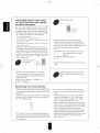
Caution regarding placement
(Except for U.S.A and Canada)
To maintain proper ventilation, be sure
to leave a space around the unit (from
the largest outer dimensions including projections)
equal to, or greater than, shown below.
Left and right panels: 5 cm
Rear panel: 10 cm
Top panel: 20 cm

READ THIS BEFORE OPERATING i
FOR U.S.A AND CANADA .............................. 120 V
Q " • = •
Units shipped to the U.S.A and Canada are designed
for operation on 120 V AC only.
Safety precaution with use of a polarized AC plug.
However, some products may be supplied with a
nonpolarized plug.
CAUTION : To prevent electric shock, match wide
blade of plug to wide slot, fully insert.
FOR EUROPE AND AUSTRALIA ......... 230V/240V
Units shipped to Australia are designed for operation
on 240 V AC only.
To ensure safe operation, the three-pin plug supplied
must be inserted only into a standard three-pin
power point which is effectively earthed through the
normal household wiring. Extension cords used with
the equipment must be three-core and be correctly
wired to provide connection to earth.
Improper extension cords are a major cause of
fatalities. The fact that the equipment operates
satisfactorily does not imply that the power point is
earthed and that the installation is completely safe.
For your safety, if in any doubt about the effective
earthing of the power point, consult a qualified
electrician.
PAN-EUROPEAN UNIFIED VOLTAGE
All units are suitable for use on supplies 230~240 V
AC.
FOR OTHER COUNTRIES ................... 115 V/230 V
Units shipped to countries other than the above
countries are equipped with an AC voltage selector
switch on the rear panel. Refer to the following
paragraph for the proper setting of this switch.
AC VOLTAGE SELECTION
This unit operates on 115/230 V AC. The AC voltage
selector switch on the rear panel is set to the voltage
that prevails in the area to which the unit is shipped.
Before connecting the power cord to your AC outlet,
make sure that the setting position of this switch
matches your line voltage. If not, it must be set to
your voltage in accordance with the following
direction.
AC voltage selector switch
::__1
Move switch lever to match your line voltage with a
small screwdriver or other pointed tool.
!/

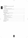
CONTENTS 1
Introduction
• UNPACKING AND INSTALLATION ....................................................................................................... 2
• READ THIS BEFORE OPERATING YOUR UNIT ................................................................................... 3
System Connections ........................................................................................................................................ 5
Front Panel Controls ...................................................................................................................................... 7
Remote Controls .............................................................................................................................................. 8
• REMOTE CONTROL OPERATION RANGE ............................................................................................ 9
• LOADING BATTERIES .............................................................................................................................. 9
Operations
LISTENING TO A PROGRAM SOURCE ................................................................................................ 10
SURROUND SOUND ................................................................................................................................ 13
ENJOYING SURROUND SOUND ........................................................................................................... 15
LISTENING TO RADIO BROADCASTS ................................................................................................ 19
RECORDING ............................................................................................................................................. 21
OTHER FUNCTIONS ................................................................................................................................ 22
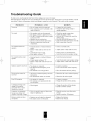
Troubleshooting Guide ................................................................................................................................ 23
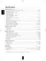
Specifications .................................................................................................................................................. 24

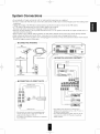
System Connections
• Do not plug the AC input cord into the wall AC outlet until all connections are completed.
• Be sure to connect the white RCA pin cord to the L(left) and the red RCA pin cord to the R(right) jacks when making audio
connections.
. Change the position of the FM indoor antenna until you get the best reception of your favorite FM stations.
• A 75 Q outdoor FM antenna may be used to fklrther improve the reception.
Disconnect the indoor antenna before replacing it with the outdoor one.
• Place the AM loop antenna as flu"as possible from the receiver, TV set, speaker cords and the AC input cord and set it to a
direction for the best reception.
• If the reception is poor with the AM loop antenna, an AM outdoor antenna can be used in place of the AM loop antenna.
• Make connections firmly and con'ectly. If not, it can cause loss of sound, noise or dmnage to the receiver.
. If the electricity fails or the AC input cord is left unplugged for more than 2 weeks, the memorized contents will be cleared.
Should this happen, memorize them again.
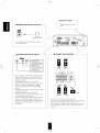
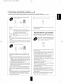
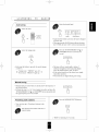
[ • CONNECTING ANTENNAS
t
FM
(OUTDOOR ANTENNA)
FM
(INDOOR ANTENNA)
300 ohmE
SUPPLIED ADAPTOR
AM loop antenna
/b_z
/- • CONNECTING 6 CH DIRECT INPUTS _
CENTER OH OUT
SUBWOOFER OH OUT
REAR
FRONT CH OUT
CH decoder I
•Use these jacks to connect the corresponding analog
outputs of 6 CH decoder oi" DVD player with 6 CH
output for Dolby Digital o1"DTS, etc.
(For details, see the operator's manual of the component
to be connected.)
¢
S
VIDEO OUT
VIDEO IN
Monitor TV
VIDEO IN
DVDplayerof additionalvideocompone,,t VIDEO OUT
Video deck / AUD O N
:EC(UNE IN)
"Tape deck or graphic equalizer
PLAY(LINE OUT)
CD player
Ta_edeckor additone audiocomponent
• The VIDEO 2 jacks may also be connected to an
additional video component such as a cable TV tuner, a
LD player or satellite system.
• The TAPE MONITOR PLAY/REC jacks may also be
connected to the LINE OUT/IN jacks of an optional
graphic equalizer.

/_-II SUBWOOFER PRE OUT connection
Powered subwoofer
• To emphasize the deep bass sounds,connect a
powered subwoofer.
- I AC INPUT CORD --
Plug this cord into awallAC
outlet.
@®
f_• CONNECTING DIGITAL INPUTS
Component with
COAXIAL DIGITAL OUT
t Component with ]
COAXIAL DIGITAL OUT
t Component with ]
OPTICAL DIGITAL OUT
• The COAXIAL oi"the OPTICAL DIGITAL OUTs
ofthe components that are connected to CD and
VIDEO 1-3 ofthis unit can be connected to these
DIGITAL INPUTS.
• A digital input should be connected to the
components such as a CD player. LD player, DVD
player, etc. capable of ontputting DTS Digital
Surround, Dolby Digital or PCMformat digital
signals.
• For details, refer to the operating instructions of the
conlponent connected.
• When makingthe COAXIAL DIGITAL
connection, be sure to use a 75_2COAXIAL cord.
not a conventional AUDIO cord.
• All ofthe commercially available opticalfiber cords
cannot be used fi0rtile eqnipment. If there is all
optical fiber cord whichcannot he connected to your
equipnmnt, consult your dealer oi"nearest service
organization.
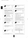
• CONNECTING SPEAKERS
Front left Rear left
®
®
Front right Rear right
Center
• Never short circuit tile +and speaker cords.
• Be sure to connect speakers firmlyand correctly according to
the channel (lePLand righ0 and the polarity (+and ).
• Be sure to usethe speakers with the impedance of over 6_2.
• For installing the speakers, refer to "Speaker placement" on
page 14.

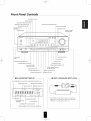
Front Panel Controls
6CH DIRECT BUTTON
REMOTESENSOR
AUDIO INPUTSELECTORBUTTON
VIDEO INPUTSELECTORBUTTON
TAPEMONITORBUTTON
TONE DIRECTBUTTON/INDICATOR
DIGITALINPUTBUTTON
!/
HEADPHONE
JACK
SPEAKER BUTTON/INDICATOR
CHANNEL SELECTOR BUTTON
ADJUST UP/DOWN
(h,/_' ) BUTTONS
TONE MODE BUTTON
SPEAKER MODE BUTTON
AUTO BUTTON
BAND BUTTON
FM MODE BUTTON
TUNING/PRESET MODE BUTTON
TUNING/PRESET UP/DOWN
(A/Y) BUTTONS
MEMORY/ENTER BUTTON
DYNAMIC RANGE BUTTON CINEMA EQ BUTTON
_- [] FLUORESCENT DISPLAY
INPUT,FREQUENCY,VOLUMELEVEL,OPERATINGINFORMATION,etc
l STEREOINDICATOR TAPEMONITORINDICATOR
_jNED LNDICATOR MEMORYINDICATOR
I I ,......
ST TUNED TAPE M _PRESET_
.....................................L:, I
..................................... } ms I
DTSDaDIGITALBaProLogic THEATER HALL LSLEEP', I
I
DTSINDICATOR
THEATERINDICATOR
DOLBY(UB)DIGITAL ...... _ /
INDICATOR I .............. I
DOLBY(aD)PRO LOGICINDICATOR I
I
PRESET NUMBER, SLEEP TIME DELAY TIMEDISPLAY
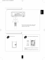
_- [] VIDEO 3 VIDEO/AUDIOiNPUT JACKS --
i VIDEO 3 i
VIDEO L AUDIO
Additional video component
t
• The VIDEO 3 jacks may be also connected to an
additional video component such as a camcorder, a
LD player or a video game player, etc.

RD-6108(A) 2003.3.4 3:53 RVl_4101Xl8
<>
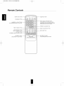
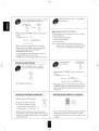
Remote Controls
DISPLAY BUTTON
POWER BUTTON
NUMERIC(I-0) BUTTONS --
Forselectingpresetstationsintunermode
TEST TONE BUTTON
DSP MODE BUTTON
DELAY TIME BUTTON
AUTO BUTTON
CHANNEL SELECTOR BUTTON
CHANNEL LEVEL
UP/DOWN(+/-) BUTTONS
\ J
SLEEP BUTTON
-- INPUT SELECTOR BUTTONS
in the standby mode, when pressing an input
selector button, the unit is turned on automaticaNy
and the desired input source is selected.
-- PRESET SCAN BUTTON
--DELAY ADJUST BUTTON
MUTE BUTTON
MASTERVOLUME
UP/DOWN(A/T)BUTTONS
,.. j

RD-6108(A) 2003.3.4 3:53 FM _4101Xl9
f
i
7m
• Use the remote control unit within a range of about
7 meters (23 feet) and angles of up to 30 degrees
aiming at the remote sensor.
!/
i
Remove the cover.
Load two batteries matching the polarity.
2x 1.5V
("AA" size)
\
• Remove the batteries when they are not used t_r a
long time.
• Do not use the rechargeable batteries(Ni-Cd type).

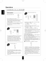
Operations
LISTENING TO A PROGRAM I
_fore operation
• Enter the standby mode.
©
• The STANDBY indicator lights up.
This means that the receiver is not disconnected fi'om
the AC mains and a small amount of cmTent is
retained to support the memorized contents and
operation readiness.
• To switch the power off, push the POWER switch again.
• Then the power is cut off and the STANDBY
indicator goes off.
In the standby mode, turn the power on.
• Each time the STANDBY button on the fl'ont panel
or the POWER button on the remote control is
pressed, the receiver is turned on to enter the
operating mode or off to enter the standby mode.
• In the standby mode, if the INPUT SELECTOR
button is pressed, the receiver is turned on
automatically and the desired input is selected.
Select the desired input source.
•Each time the "AUDIO" button is pressed, the input
source changes as follows;
--* TUNER --+ CD _ AUX_
!
(frequency display)
• Each time the "VIDEO" button is pressed, the input
source changes as follows;
i--4,VIDEO 1 _ VIDEO 2 _ VIDEO 3
•When the TAPE MONITOR button is set to on so that
"TAPE M" indicator lights up, other inputs can not be
heard fl'om the speakers.
To listen to an input som'ce other than TAPE MONITOR,
be sure to set the TAPE MONITOR button to off.
TAPE MONITOR function
You can connect either a tape deck o1"a ga'aphic equalizer to
the receiver's TAPE MONITOR jacks.
Only when you listen to the component connected to these
jacks, set the TAPE MONITOR button to on.
If you connect a 3-head tape deck, you can listen to the sound
being recorded during recording, not the som'cesound.
For further dams, refer to the operating instructions of the
component connected.
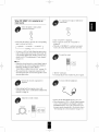
==When selecting the 6 CH DIRECT as desired,
Switch the speakers on.
o
SPEAKER
ON,O,,
•Then the SPEAKER indicator lights up and the
sound can be heard fl'om the speakers connected to
the speaker terminals.
• When using the headphone for private listening,
press the SPEAKER button again to switch the
speakers off.
GCHDIRECT
©
• "6-DIRECT" is displayed and the 6 sepm'ate analog
signals from 6 CH decoder connected to this unit pass
through the tone (bass, treble) and volume circuits
only and directly transfer to the speakers. (In case that
the TAPE MONITOR button is set to on, the TAPE
MONITOR button is automatically set to off.)
• Press the 6 CH DIRECT button or select the desired
input source to cancel the 6 CH direct flmction.
•These 6 separate analog signals can be heard only, not
recorded.

When CD, VIDEO 1-3 is selected as an
input source
Select the digital or analog input
connected as desired.
DIGITAL
INPUTS
©
• Each time this button is pressed, the corresponding
input is selected as follows ;
y o(ptical) 1 _ c(oaxial) 1 --+c(oaxial) 2
A(nalog) - q
• To listen to a DTS o1"Dolby Digital program som'ce
in the 2-CH downmix mode, in the stereo mode, the
corresponding digital input should be selected. (For
details, refer to "Downmixing into 2 fi'ont channels"
on page 18.)
mNotes :
• When the selected optical or coaxial digital input is
not connected, the selected digital input display is
flickering, meaning no sound. (Refer to
"ENJOYING SURROUND SOUND" on page 15.)
• The sound fl'om the component connected to the
selected digital input can be hem'd regardless of the
selected input source.
Operate the selected component for
playback.
• When playing back the program sources with
surround sound, refer to "ENJOYING SURROUND
SOUND'" on page 15.
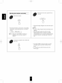
Adjust the (overall) volume.
MASTER VOLUME I
To compensate for edgy or shrill movie
sound tracks.
CINEMA EQ
• Then "C-EQ ON" is displayed.
• Press it again to cancel, the "C-EQ OFF" is
displayed.
• When the 6 CH DIRECT is selected as an input
source, the cinema EQ function does not work.
To mute the sound.
• "MUTE" will flicker.
• To resume the previous sound level, press it again.
To listen with the headphones.
PHONES
• Ensure that the SPEAKER button is set to off.
• When listening to a DTS or Dolby Digital program
source, if the headphones are plugged in and the
SPEAKER button is set to off, it enters the 2-CH
downmix mode automatically. (For details, refer to
"Downmixing into 2 front channels'on page 18.)
!/

Adjusting the tone(bass and treble)
Enter the tone mode.
TONE MODE
• Each time this button is pressed, the con'esponding
tone mode is selected and shown for 3 seconds as
follows:
yBASS _TRBL(treble) _
• Note: When the TONE DIRECT indicator is
lighting up, the tone mode cannot be
entered.
At the desired tone mode, adjust the tone
as desired.
• If the tone display disappears, start from the step 10
again.
• Notes:
• Extreme settings at high volume may damage your
speakers.
• When the digital signals from DTS or Dolby
Digital program sources are input in available
surround mode, the tone cannot be adjusted and the
tone direct function is automatically switched to
ON.
To listen to a program source without the
tone effect.
TONE
DIRECT
©
• The TONE DIRECT indicator lights up and the
sound that bypasses the tone circuitry will be
heard.
• To cancel the tone direct function, press this
button again.

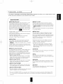
I
SURROUND SOUND
i
• This receiver incorporates a sophisticated Digital Signal Processor that allows you to create optimum sound
quality and sound atmosphere in your personal Home Theater.
_urrou nd modes
• DTS Digital Surround
DTS Digital Surround(also called simply DTS) is a multi-
channel digital signal format which can handle more
amount of data than Dolby Digital, providing better audio
quality. Though the number of audio channels is 5.1 (front
left, front right, center, rear(surround) left, rear(surround)
right and Low Frequency Effects) which is same as Dolby
Digital, discs bearing the .... provides fat sound
• Dolby Pro Logic
Dolby Pro Logic is a specially encoded two channel
surround format which consists of four channels (front
left, center, fl'ont right and surround). Sources bearing the
4' [_DIDOLBY SURROUND I " provide the theater-like surround
sound.
The surround channel is monaural, but is played through
two sm'round speakers.
and better signal - to - noise ratio, thanks to the lower audio
compression ratio format.
It also provides wide dynamic range and better separation,
resulting in magnificent sound.
"DTS" and "DTS Digital Surround" are registered
trademarks of Digital Theater Systems,Inc.
• Dolby Digital
Dolby Digital is the multi-channel digital signal format
developed by Dolby Laboratories. Discs bearing the
" [']["][g6_ " includes the recording of up to 5. 1 channels
DIGITAL
of digital signals, which can reproduce much better sound
quality, spatial expansion and dynamic range characteristics
than the previous Dolby Surround effect.
• Dolby Pro Logic II surround
This mode applies conventional 2- channel signals such as
digital PCM or analog stereo signals as well as Dolby
Surround signals, etc. to surround processing to offer
improvements over conventional Dolby Pro Logic circuits.
Dolby Pro Logic ll surround includes 4 modes as follows:
• Dolby Pro Logic n MOVIE
When enjoying movies, this mode allows you to fnrther
enhance the cinematic quality by adding processing that
emphasizes the sounds of the action special effects.
• Dolby Pro Logic n MUSIC
When listening to music, this mode allows you to further
enhance the sound quality by adding processing that
emphasizes the musical effects.
• Dolby Pro Logic n MATRIX
When listening to poor FM broadcasts, this mode allows
you to further enhance the sound quality by the ultimate
cure for poor FM stereo signals.
• Dolby Pro Logic 11CUSTOM
This mode reproduces a delayed signals fl'om the surround
channels to emphasize the sense of expansion.
• Dolby Virtual
This mode employs sophisticated digital processing to
create the illusion of "phantom" speakers, this mode
allows you to experience sma'ound sound effects from the
Dolby Digital, Dolby Surround or 2-channel(recorded in
digital PCM or analog stereo) sources, through just a
single pair of fl'ont speakers.
Manufactured under license from Dolby Laboratories.
"Dolby", "Pro Logic", and the double-D symbol are
trademarks of Dolby Laboratories.
• The following modes apply conventional 2-channel
signals such as digital PCM or analog stereo signals to
high performance Digital Processor to recreate sound
fields artificially.
•THEATER
This mode provides the effect of being in a movie theater
when watching a movie source.
•HALL
This mode provides the ambience of a concert hall l_r
classical music sources such as orchestral, chamber music,
or an instrumental solo.
•STADIUM
This mode provides the expansive sound field to achieve
the true stadium effect when watching baseball or soccer
games.
•CHURCH
This mode provides the ambience of a church for baroque,
string orchestral or choral group music.
• When the 6 CH DIRECT INPUTs are connected to the 6 CH decoder for a surround sound such as Dolby Digital or DTS,
etc., you can enjoy the corresponding surround sound, too. (For details, see the operator's mmmal of the component to be
connected.)
!/

RD-6108(A) 2033.3.4 3:54 PM _-t101X114
Delay time
When the center spe_Lkeror the rear speakers is(are) closer to the listener than the front speakers, the sound frolTl
the center speaker or the rear spe_Lkerscan arrive at the listener's ears earlier than the sound from the front
speakers.
In this case, the imaging is not as sharp and stable as it could be.
For audible improvement, the sound from center speaker can be delayed with the center delay time setting so that
the sound from the front and the center speakers will be heard at the same time and the sound from the rear
speakers can be also delayed with the rear delay time setting so that the sound from the front and the rear speakers
will be heard at the same time.
The optimmn delay time will be different according to the room size and the acoustic properties. It is
recolmnended that you try several times to obtain the best effect.
. It is adjustable in Dolby Digital, Dolby Pro Logic II, Dolby Pro Logic or Dolby Virtual modes. (For details,
refer to "In Dolby Digital, Dolby Pro Logic II, Dolby Pro Logic or Dolby Virtual mode, adjusting delay times of
the speakers" on page 18)
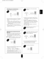
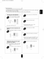
Speaker placement
To obtain the best sun'ound sound effect in your home, place the speakers as
follows;
• Front speakers: Place each front speaker about im (40 _) from the TV set.
° Center spe_Lker:Place the center speaker either above or below the TV set to
assure good visualization of center channel program.
. Rear speakers: Place the rear speakers approximately im above the ear level
of a seated listener on the direct left and right of them or
slightly behind.
. Subwoofer: Reproduces powertkfl deep bass sounds. Place a powered
subwoofer anywhere in the front as desired.
. The ideal surround system needs all the speakers listed above.
To obtain the best SUlToundeffects, the speakers except the subwoofer should
be tull range speakers.
Note: To avoid interference with the TV picture, use only magnetically
shielded center and front speakers.
• For your reference, the sound from each channel can be reproduced according
to the surround modes as follows:
DTS Dolby Digital
FrontL/R o
Center o ::
RearL/R
Subwoofer
Dolby Pro Logic II
_2
Dolby Pro Logic
o
Dolby Virtual
2
2
OtherSurround
O
_7
I:
Stereo
1;
*Depending on the speaker settings, the sound from the corresponding channels cannot be reproduced.
(For details, refer to "Adjusting the speaker settings" on page 16.)
6 CH DIRECT
o
o

RD-6108(A) 2003.3.4 3:54 PM _-t101X115
ENJOYING SURROUND SOUND I
• Surround sound effect will not work properly if the signal passes through a graphic equalizer
Please refer to your equalizer operating instructions for guidance on switching off (or defeating) the equalizer
Depending oi1tile input digital signal foimah select the
desired decoding mode
AUTO
©
or
•Each time @e AUTO button is pressed, the decoding mode changes as
%llows:
IN iUTO : Tile mpm digital signal fommt(DTS, Dolby Digital or
PCM(2 channel stei_o), etc.) used 1)3,the selected digital hiput
source is detected aummaucally m perform the necessary
&coding process for optimmn sunound modes
IN DTS : Tile DTS signal pi_ocessingis performed only when DTS
signals are input
IN t;CM : TIle PCM signal processhig is perfonaed only when PCM
signals me input
mNotes:
•Only when the digital input is selected as signal input fol tile input sottrces
except TUNER, AUX and TAPE MONITOR, the decoNng mode can be
selected
•Noise may be generated at the beginning of playback and while sealching
during DTS playback in the IN AUTO mode In this case. try playing in
tile IN DTS mode
Select the desired sttrround mode
DSPMODE
©
or
•Each time the DSP MODE button is plessed, the SlllToundmode changes
depending ml the input signal format and the selected decoding mode as
follows:
-;_When Dolby Digital signals am input in tile IN AUTO mode, role of the
following modes can be selected depending on tile tmmber of the recorded
channels
• DofbyDigital5.1-channelsources:DOLBYDIGITALandDOLBYVIRTUAL.
• DofbyDigital2-channelsources:DOLBYPROLOGICIIMOVIE,DQLBYPRO
LOGICDOLBYPROLOGICIIMUSIC DOLBYPROLOGICIIMATRIX,
DOLBYPROLOGICIICUSTOMandDOLBYVIRTUAL
,:, When PCM(2 challnci stereo) signals are input 111tile IN"AUTO ot"IN PCM
mode, one of the following modes can be selected :
DOLBYPROLOGICIIMOVIEDOLBYPROLOGICDOLBYPROLOGICtlMUSIC
DOLBYPROLOGICIIMATRIXDOLBYPROLOGICIICUSTOM,DOLBYVIRTUAL,
CHURCH,THEATER,HALLandSTADIUM
•When tile analog input is selected as signal input and analog stereo signals
are input, you can select the desked of these above surlottIld modes, too
•Howevm, when DTS signals are input in the IN AUTO or IN DTS mode,
the DTS mode will be selected regardless of uring tile DSP MODE button
mNotes:
•When the selected decoding mode is not matched to the input signal fonnat,
no somld is head Tilelefore, he sine to select the lequired decoding mode
and tile available smTomld mode accoldhlg to tile input signal fonuat.
•When the 6 CH DIRECT is selected as an input sol_rce,tile decoding and
sm_v_mldmodes camlot be selected
mltqlen canceling the sttriound mode for stereo operation
STtRK,
O>
• Then the stereo mode is selected
• To cancel the stereo mode, select the desired sttrround mode with using
the DSP MODE button
Adjustingthe Dolby Pro Logic II parameters
• When selecting the Dolby Pro Logic II Music and Custom modes, you
Call adjtlst tile various surround paranleters for optinlunl SUlTound effect
l_]ile scrolling "PL II MUSIC"(for Dotby Pro Logic II
Music mode) or "PL II CUSTOM'(for Dolby Pro
Logic II Custom mode), press the MEMORY/ENTER
button to select the desired parameter
MEMO/ENTER
• Each time this button is plessed, @e parameter changes and is displayed
%r 5 seconds as %llows:
e>Panorama mode('PANO") : This mode extends the front steleo image
to include the sulIotmd speakers for an exciting ' wraparound"eft?ct
with side wall imaging Select 'OFF" or "ON"
€.Center width conb:ol(' C WID") :This control adjusts the center image
so it may be heard only from the center speaker, only from the
left!iight speakers as a phantom image, or from all ttuee flout speakers
to valying degrees The connol can be set in 8 steps flora 0 to 7.
¢.Dimension controlCDIMEN') : This control gradually adjusts the
soundfield either towards the flout or towards tile i_ar Tile control can
be set in 7 steps flora 4 to +2
> 7 kHz Low Pass Filter('LPF") : Select 'OFF" or 'ON" to mrn off or
on tile pass filter on tile sttrround channels
>ShelfFilter('SH F"): Select 'OFF" or ' ON" to mrn off or on the
shelf filter on the sttnound channels
4-Right Sttrround Channel Polarity Inversion( 'PO I") : Select 'OFF" or
"ON" to turn oft or on the polarity inversion
._Automatic Balancing(' BAL") : Select ' OFF" or "ON" m tmn oft or
on tile automatic balancing
• If the Dolby Pro Logic II Music or Custom display disappears, you
cannot select the parameter Ii1this case, select the desiled sttrround
mode again by pressing the DSP MODE button
• In the Dolby Pro Logic II Music mode, you cannot select the 7 kHz Low
Pass Filter, Shelf Filter, Right Sunound Channel Polarity Inversion and
Automatic Balancing
• For yotli refel_nce, the initial settings fol parameters are as %llows:
"PANO" : "OFF", _C WID" : '0%' DIMEN" : '0% ' LPF" : 'OFF",
'SH F" : "OFF", 'PO I" : 'ON", ' BAL" : 'OFF".
!/

RD-6108(A) 2003.3.4 3:54 PM _4101XI16
At the desired parameter,
adjust it as desired.
• If the pm'ameter display disappears, start from the
step 3 again.
Adjusting the speaker settings
• Adjust the settings of front, center ,rear speakers and
subwoofer connected.
• If the speaker setting is adjusted to "S", the low range
bass sound of the channel(s) is redirected to the
subwoofer or the front channels and if the speaker
setting is adjusted to "N", the sound of the channel(s)
Repeat the above steps 3 and 4 to adjust
other parameters.
mNote:
• In the Dolby Pro Logic II Customer mode, you cannot set both of
the 7 kHz Low Pass Filter and Shelf Filter to ON sinmltan¢ously.
If so, the fitter set previously is automatically changed to OFF.
Select the desired speaker
setting.
• Each time this button is pressed, one of 11 different
speaker settings is selected and displayed for 8
seconds as follows;
is redirected to other channels.
Press the SPEAKER
MODE button for more
than 2 seconds to enter the
front-center-rear speaker
mode.
SPEAKER
MODE
FL CS RS, FL<TL RS, FL CL RL,
FL -CL-RN, FL-CS -RL, FL -£:N -RL,
FL CS RN, FL CN RS, FS_2S RS,
FS-CS-RN and FS -CN -RS
• In the displays, F stands tbr Front, C tbr Center, R
tbr Rear, L for Large, S for Small and N tbr None.
• When judging whether a speaker is Large or Small,
• The fi'ont-center-rem" speaker setting is displayed.
•When the SPEAKER button is set to off or the 6 CH
DIRECT is selected as ml input som'ce, the speaker
mode function cannot be available.
•When it is in the stereo or Dolby Virtual mode, only
the subwoofer setting can be adjusted.
Memorize the desired MEMO/ENTER
speaker setting
while it is displayed.
• The desired speaker setting is memorized and then
it enters the subwoofer mode.
• If the speaker setting display disappears, start from
the above step 6 again.
Memorize the subwoofer MEMO/ENTER
setting while it is
displayed.
• If the subwoofer setting display disappears, start
from the _abovestep 6 a_ain.,_
please note that a standard large speaker can fnlly
reproduce sounds below 80 Hz.
The following speaker settings cannot be selected.
Front :Small, Center : Large and Rear : Large(FS-
CL-RL) or Center : None and Rear : None(CN-RN)
setting.
Select the desired
subwoofer setting.
Checking the speaker setting
SPEAKER
MOOE
CCC_
• Each time this button is pressed briefly, the fi'ont-
center-rear speaker or subwoofer setting is displayed.
• Each time this button is pressed, the subwoofer setting
changes and is displayed for 8 seconds as follows;
BBW(oofer) Y(es): When using a subwoofer
W(oofer) N(o) : When not using a subwoofer
• In case that the front speaker is set to "S", the
subwoofer is automatically set to "Y".

RD-6108(A) 2003.3.4 3:54 PM _t101X117
Adjusting each channel level
Select the desired channel.
• Each time this button is pressed, the corresponding
channel is selected and displayed tbr 3 seconds as
follows;
[_ Front Left _ Center _ Front Right _ Rear Right
(Dolby Digital or DTS LIFE) _)SubWoofer _ Rear Left
( ): Adjustable only when the digital signals flmn Dotby Digital or
DTS program somce that includcs LFE signal are input in the
available surround mode
• When it is in the stereo or Dolby Virtual mode, or
the speaker setting is "N", center, rein"or subwoofer
channel will not be selected.
Adjusting each channel level with
test tone
• Only"when it is in available sm'round modes except
the Dolby Virtual and stereo modes, the volume
level of each channel can be adjusted easily with the
test tone function.
mNote: When the 6 CH DIRECT is selected as an input
som'ce, the test tone function does not work.
Enter the test tone mode.
\ /
• The test tone will be heard fl'om the speaker of each
channel for 2 seconds as follows;
c Front Left _ Center --+ Front Right
SUBwoofer _--Rear Left _- Rear Right
• o
When the speaker setti% is "N", the test tone of the
con'esponding channel is not available.
• When the selected decoding mode is not matched to the
input signal format, the test tone function cannot work.
Adjust the level of the selected channel
as desired.
d ......
The LFE level can be ad usted within the range of
-10~0 dB and other channel levels within the range
of-15~+15 dB.
In general, we recommend the LFE level to be
adjusted to 0 dB. (However, the recommend LFE
level for some early DTS software is -10 dB.) If the
recommended levels seems too high, lower the
setting as necessary.
If the channel display disappears, start fi'Oln the
above step 11 again.
Repeat the above steps 11 and 12 to
adjust other channel levels.
At each channel, adjust the level as desired
until the sound level of each speaker is
heard to be equally loud.
or
• You can select the desired channel and adjust its
level with repeating the steps 11 and 12 in
"Adjusting each channel level" procedure.
Cancel the test tone function.
!/

In Dolby Digital, Dolby Pro Logic 11,Dolby
Pro Logic or Dolby Virtual mode, adjusting
delay times ofthe speakers
• In case of Dolby Digital, Dolby Pro Logic II o1"Dolby
l:h'oLogic mode, when the distances from the prime
listening position to fl'ont left, center, front right, rem"
left and rear fight speakers m'e same, the basic settings
are as follows according to the SmTound modes;
In tile Dolby Digital mode,
Center delay trine : 0 ms, Rear delay time :0 ms
In the Dolby Pro Logic II Music, Matrix orCustom mode,
Rear delay time : 0 ms
In tile Dolby Pro LogicII Movie, Dolby Pro Logic mode,
Rear delay time : 10 ms
• If the center or the rem"speaker(s) is(re'e) not at the
same distance from the prime listening position as the
front speakers, increase or decrease the center delay
time by 1 ms tbr every about 30 cm(1 foot) it is closer
or farther away and increase or decrease the rear delay
time by 5 ms for eve_2¢about 1~1.5 m(3~5 feet) it is
closer o1"farther away.
Check the delay" time
to be adjusted.
• The delay time will be displayed for 5 seconds.
• The con'esponding delay time is displayed. The
center delay time can be adjusted in the Dolby
Digital mode only.
• In the Dolby Virtual mode, "NARROW" or
"WIDE" is displayed.
Adjust the delay time.
Each time this button is pressed in the Dolby
Digital, Dolby Pro Logic II or Dolby Pro Logic
mode, the delay time changes in regular intervals.
Each time this button is pressed in the Dolby Virtual
mode, the delay mode changes as tbllows:
NARROW: Relatively lon e distance from the
l prime listening position to front
] speakers.
WILDE:Relatively short distance.
• If the delay time disappears, start from the step 17
again.
In Dolby Digital mode, repeat the above
steps 17 and 18 to adjust the rear delay
time.
Downmixing into 2 front channels
• Allows the multi-channel DTS or Dolby Digital signals
to be reproduced through only two speakers or through
headphones.
• When the digital signals fi'om the DTS or Dolby Digital
program sources are input in available smTound mode,
press the STEREO button.
STeReO
©
• "ST" and the DTS or Dolby Digital indicators light up,
meaning it enters the 2-CH dowmnix mode, and then the
discrete mnlti-channels(except LFE) are mixed down into
2 front channels.
To cancel the 2-CH downmix mode, select the
desired surround mode with using the DSP MODE
button.
When the playback of the source on the player is
stopped or inten'upted, etc., the 2-CH downmix
mode is not canceled even though "ST" and the
DTS or Dolby Digital indicators go off.
If the headphones are plugged and the SPEAKER
button is set to off while the digital signals ti"om the
DTS and Dolby Digital program sources are being
input, it will enter the 2-CH downmix mode
automatically(but only the DTS or Dolby Digital
indicator lights up still) and if the headphones are
unplugged and the SPEAKER button is set to on in
the 2-CH downmix mode, it will return to the
previous mode.

LISTENING
_uto tuning
Select the tuner.
AUDIO
©
or
TO
Select the tuning mode.
RADI01
T/P MOD£
•Each time this button is pressed, the mode changes
as t_llows;
K Tuning mode : "PRESET" goes off.
q
h'eset mode : "PRESET" lights up.
Select the desired band.
BANO
',FI I--I I-- 17 1
=--'-;'11
BAND FREQUENCY
• Each time this button is pressed, the band is changed
to FM or AM.
• When pressing the BAND button without selecting
the TUNER, the tuner will be selected automatically.
Press the TI_NING/PRESET UP(A) or
DOWN(v) button for more than 0.5
second.
• TUNIN6/PRESET •
• The tuner will now search until a station of
sufficient strength has been found. The display
shows the tuned frequency and "TUNED".
• If the station found is not the desired one, simply
repeat this operation.
• Weak stations are skipped during auto tuning.
Manual tuning
• Manual tuning is useful when you already know the frequency of
the desired station.
• Perform the steps 1 to 3 in "Auto tuning" procedure and press the
TUNING/PRESET UP(A) or DOWN(V) button repeatedly until
the right frequency has been reached.
• TUNIN6/PRESET •
Presetting radio stations
• You can store up to 30 preferred stations in the
memory.
Tune in the desired station with auto or
manual tuning.
Press the MEMORY/ENTER button.
MEMO/ENTER
•"MEM" is flickering for 5 seconds.
!/

Select the desired preset number (1~30) and
press the MEMORY/ENTER button.
• TUNING/PRESET • MEMO/EN_
• When using the NUMERIC buttons on the remote
control.
Examples) For "3":
1 wiNin 2 seconds 5
For "15" : @_ O
For "30": 6)
• The station has now been stored in the memory.
• When using the NUMERIC buttons, the station is
stored autolnatically without pressing the
MEMORY/ENTER button.
• A stored frequency is erased from the memo U by
storing another frequency in its place.
• If "MEM" goes off, start again from the above step 2.
Repeat the above steps 1 to 3 to memorize
other stations.
• MEMORY BACKI P FUNCTION
The following items, set before the receiver is turned
Tuning to preset stations
After selecting the tuner as an input
source, select the preset tuning mode.
off, m'e memorized.
• INPUT SELECTOR settings
• Surround mode settings
• Preset stations,etc.
Note : If the electricity fails or the AC input cord is
disconnected for more than 2 weeks, they are all
T/P MODE
• Then "PRESET" lights up.
Listening to FM stereo broadcasts
• While listening to FM broadcasts.
• Each time this button is pressed,
the FM mode changes as t_llows;
V_ Stereo mode : "ST" lights up. q
Mono mode : "ST" goes off. <_
FM MODE
• When FM stereo broadcasts are poor because of
weak broadcast signals, select the FM mono mode to
reduce the noise, then FM broadcasts are reproduced
in monaural sound.
cleared. So you should memorize them again.
Select the desired
preset number.
• When using the NUMERIC buttons on the remote
control.
3
Examples) For"3": .._,
q withr_2 seconds 5
For "15": @,._"" _ _CD_*",
o s wit/in 2seconds o
For "30": O,/or ,CD)_, _ _,)
• When selecting the desired preset number with the
NUMERIC buttons, the desired preset station will be
tuned to automatically without selecting the preset
tuning mode.
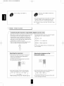
Scanning preset stations in sequence
• The receiver will start sc_ning the stations in the preset
sequence mid each station is received t_r 5 seconds.
• At the desired station, press this button again to stop
scanning.
Page is loading ...
Page is loading ...
Page is loading ...
Page is loading ...
-
 1
1
-
 2
2
-
 3
3
-
 4
4
-
 5
5
-
 6
6
-
 7
7
-
 8
8
-
 9
9
-
 10
10
-
 11
11
-
 12
12
-
 13
13
-
 14
14
-
 15
15
-
 16
16
-
 17
17
-
 18
18
-
 19
19
-
 20
20
-
 21
21
-
 22
22
-
 23
23
-
 24
24


Sherwood RD-6108 Owner's manual
- Category
- AV receivers
- Type
- Owner's manual
Ask a question and I''ll find the answer in the document
Finding information in a document is now easier with AI
Related papers
Other documents
-
LG FA-3000AWE Owner's manual
-
-
-
-
Yamaha NX-S100S Owner's manual
-
Aiwa Z-HT65 Owner's manual
-
Sony DAV-FX10 Owner's manual
-
-
-