Page is loading ...

SVx41HDI Series Server Remote Control: Instruction Guide
i
Table of Contents
INTRODUCTION 1
FEATURES 1
BEFORE YOU BEGIN 1
Required Cables and Hardware 1
INSTALLING THE SERVER REMOTE CONTROL 2
Disabling Mouse Acceleration on the Managed Computers 3
NETWORK CONFIGURATION METHODS EXPLAINED 3
Web Configuration Using DHCP 4
Terminal Configuration Using a Serial Cable 4
CONFIGURING THE KVM FOR YOUR NETWORK 6
Using the Web Interface 6
Using the Terminal Interface via Serial Port 12
ACCESSING THE VNC INTERFACE 13
Web Interface 13
Native VNC Client 14
SSH Tunnel (with Native VNC client) 15
USING THE VNC MENU 15
Welcome Window 16
Bribar Feature 16
Main Menu 18
VirtKeys Menu 19
Video Tuning Menu 19

SVx41HDI Series Server Remote Control: Instruction Guide
ii
ACCESSING KVM FEATURES 22
Cascade Configuration 22
OSD Operations 23
Hot Key Commands 27
Changing Your Configuration 28
TROUBLESHOOTING 29
SPECIFICATIONS 31
SUPPORTED PROTOCOLS 32
SUPPORT AND WARRANTY INFORMATION 33
REGULATORY COMPLIANCE STATEMENTS 33
APPENDIX A: ABOUT SECURITY CERTIFICATE WARNINGS 34
APPENDIX B: USING THE ADVANCED VIDEO TUNING FEATURE 35
APPENDIX C: GETTING PEAK PERFORMANCE 37
APPENDIX D: THE IPMI UPGRADE OPTION 38
APPENDIX E: THE MODEM OPTION UPGRADE 45
APPENDIX F: USING OPTIONAL R-PORT DEVICES 51
NOTE: Since firmware for our Server Remote Control Products is constantly evolving to
offer more functionality and improvements, some of the options and instructions presented
in this manual may differ from your unit. To obtain the latest documentation and support
information for this product, please visit www.startech.com.
4 August 2004 (Rev. A)

SVx41HDI Series Server Remote Control: Instruction Guide
1
Introduction
Thank you for purchasing a StarTech.com SVx41HDI series Server Remote Control with
integrated KVM. Using the Internet or your TCP/IP enabled network, you can now remotely
monitor and control critical PC servers and workstations using an industry-standard Web
browser or VNC client.
Features
• Supports industry-standard networking and management protocols such as TCP/IP and
SNMP
• Offers secure management options including SSL encryption, SSH tunneling, and RADIUS
authentication
• Platform independent: can be managed using any Java-enabled Web browser
• One remote management point for multiple computers
Before You Begin
This section describes the cables and other hardware that you may wish to use when setting up
and configuring your new Server Remote Control. We suggest you review this section carefully
before beginning the installation process.
Contents
Your package should contain the following:
• 1 x SVx41HDI Server Remote Control unit
• 1 x Power adapter
• 1 x Instruction Guide
• 1 x Rack Mount screw kit
• 1 x DB9 RS-232 null modem serial cable
Required Cables and Hardware
Depending on your needs, you may need one or more of the following
cables:
All applications
• 1 x Straight-through Ethernet patch cable (connects unit to your LAN)
StarTech.com part number: M45PATCHxxxx
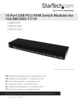
• StarTech.com PS/2 3-in-1 KVM Cables (1 for each managed computer
connected via PS/2)
StarTech.com part number: SVECONxx
• StarTech.com USB 3-in-1 KVM Cables (1 for each managed computer connected via USB)
StarTech.com part number: SVECONUSxx
SVECONxx
SVECONUSxx
SVx41HDI Series Server Remote Control: Instruction Guide
2
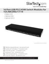
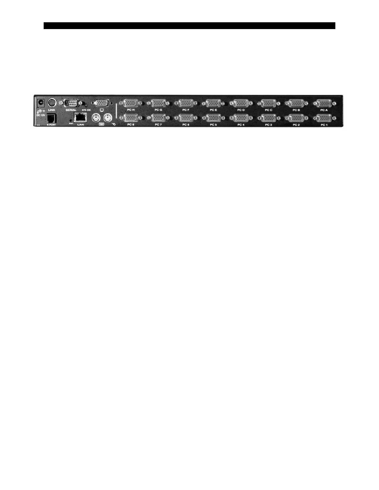
DC 12V Serial VGA Out Managed Computer Input (Non-Cascadable)
(Power)
Installing the Server Remote Control
NOTE: The instructions here and elsewhere in the manual refer to port designations of the
SV1641HDI, the 16-port version of the Server Remote Control. For other versions, note the
following:
SV841HDI: Ports PC A~H = Ports PC A~D and Ports PC 1~8 = PC 1~4 on your product
SV441HDI: Ports PC A~H = Ports PC A~B and Ports PC 1~8 = PC 1~2 on your product
The restrictions on functions such as cascading and the assignment of master and slave
units also apply to all versions of the product.
1. Ensure that the Server Remote Control unit and the computers to be managed are powered
off.
2. If desired, mount the unit in a standardized rack or cabinet.
3. Connect a standard straight-through Ethernet patch cable to the LAN port on the rear panel
of the unit.
4. Connect the opposite end to your network hub, switch, or terminated wall outlet.
5. If you wish to use the product as a local console, connect a standard keyboard (purple
connector) and mouse (green connector) to the PS/2 ports, as marked on the rear panel.
6. Connect a VGA monitor to the video-out port on the rear panel of the unit.
7. (a) If you are using PS/2 connections to your managed computers, connect the end of the
SVECONxx cable that has three connectors (keyboard, video, mouse) to the keyboard,
mouse, and VGA Out ports on a computer (often a server or other critical system). Connect
the opposite end (with a single VGA-style connector) to one of the PC A~H or PC 1~8 ports
on the rear panel of the Server Remote Control. Repeat this procedure for each PS/2-enabled
managed computer. You will be able to add additional managed computers later with the
Server Remote Control powered on.
(b) If you are using USB connections to your managed computers, connect the end of the
SVECONUSxx cable that has two connectors (USB, video) to an available USB port and
VGA Out port on the computer (often a server or other critical system). Connect the
opposite end (with a single VGA-style connector) to one of the PC A~H or PC 1~8 ports on
the rear panel of the Server Remote Control. Repeat this procedure for each USB-enabled
managed computer. You will be able to add additional managed computers later with the
KVM powered on.
LAN Keybd/Mouse Managed Computer Input (Cascadable)

SVx41HDI Series Server Remote Control: Instruction Guide
3
8. Power on the Server Remote Control by connecting the AC adapter to a suitable power
source and connecting the opposite end to the DC 12V port on the rear panel of the unit.
9. Power on each of the managed computers, observing normal startup procedures.
NOTE: You can choose to mix managed computers connected via PS/2 and USB connections as
necessary with no impact on features or functionality.
NOTE: Steps 5 and 6 are necessary only if you wish to have the ability to manage the KVM and
its computers locally (i.e. not over the Internet or LAN). While not required, adding these
devices is highly recommended for ease of administration.
NOTE: The KVM also has the ability to “cascade” multiple KVMs to increase the total number
of possible managed computers. If you wish to take advantage of this feature, refer to the section
“Cascade Configuration” in this manual.
Disabling Mouse Acceleration on the Managed Computers
Many operating systems offer a feature called mouse acceleration that allows the user to adjust
the responsiveness of the cursor on the screen to physical movements of the mouse. While this is
usually a beneficial interface enhancement, it can interfere with the operation of the unit and
should be disabled on the managed computers before a remote session is attempted. Follow the
instructions below to disable mouse acceleration for the operating system installed on each
managed computer.
Windows 98
1. From the Control Panel, click on Mouse.
2. From Mouse Properties, click on Motion tab.
3. Make sure the Pointer speed bar is centered and Acceleration is set to None.
Windows 2000
1. From the Control Panel, Click on Mouse.
2. From Mouse Properties, click on Motion tab.
3. Make sure that the Pointer speed bar is centered and Acceleration is set to None.
Windows XP and Windows Server 2003
1. Go to “Pointer Options “ and turn off “Enhance Pointer Precision.”
2. Make sure that the Pointer speed bar is centered.
Linux, Unix and X-Windows
1. Add this command to your xinitrc, xsession or other startup script:
xset m 0/0 0
Network Configuration Methods Explained
The Server Remote Control offers two distinct methods for configuring the unit for your
network. The method that will work best for you will depend on your level of experience and
your specific network configuration.

SVx41HDI Series Server Remote Control: Instruction Guide
4
Web Configuration Using DHCP
This method requires that your network implement DHCP (Dynamic Host Configuration
Protocol), usually on a server or network access device such as a router that dynamically allows
devices to join the network without pre-configuration. It also assumes that you will have easy
access to your network’s DHCP log, since you will need to know the IP address of the unit to
complete the configuration over your Web browser. (If you are unsure of how to access your
network’s DHCP log, contact your System Administrator for details.) If the unit is powered on
and connected to the network via LAN port on the rear panel, it will automatically attempt to
lease an IP address using DHCP. Before you can begin the configuration process, you will need
to access the DHCP log from your file server or other device that acts as the DHCP server on the
network. A simple DHCP log looks similar to the following:
The information displayed for your own network may vary significantly from the data displayed
in the image, but should supply (at minimum) three essential details: IP address, MAC address,
and device (or machine) name for the computers and other devices connected to your network.
The values for the unit tested above are as follows:
IP Address: 192.168.22.4
MAC Address: 00-0E-C5-00-08-1A
Device Name: (none)
The easiest way to identify your Server Remote Control on the network is by its MAC address, a
unique hardware identifier that is specific to your unit. The MAC address of the unit can be
found on a white sticker on the bottom of the unit. Write down this number and keep it for
future reference. Once you locate the MAC address of your unit in the DHCP log, you can
match it to its leased IP address and proceed with the Web configuration.
NOTE: Once you have located the IP address of the unit switch and wish to proceed with the
Web configuration, do not power off the unit or your DHCP server, since it might lease a
different IP address. Should this happen, re-examine the DHCP log to verify the IP address
again.
Terminal Configuration Using a Serial Cable
Configuring the unit using a serial cable is the best choice if you need to pre-configure the unit
before attaching it to a network, i.e. when sending to a branch office, customer site, etc. or are
not using DHCP on your network. In general, the Web configuration is far preferable because of
its intuitive interface and the fact that you do not have to be within close physical proximity to do
the configuration. However, if you wish to use the serial cable method to configure the Server

SVx41HDI Series Server Remote Control: Instruction Guide
5
Remote Control, you can use any typical communication software package (UNIX: tip, cu,
kermit, minicom; Windows: HyperTerminal, kermit).
Using the DB9 female-to-female null-modem serial cable (provided) connect one end of the
cable to the SERIAL port on the rear panel of the SVx41HDI. Connect the opposite end to the
serial port on the computer you are using to configure the unit. Configure the terminal software
with “8N1” settings:
Connection speed: 115200 bps
No. of bits: 8
Parity: None
Stop bits: 1
Flow Control: None

SVx41HDI Series Server Remote Control: Instruction Guide
6
Configuring the KVM for Your Network
NOTE: As firmware for this product evolves, some of the menu options may change and
therefore these screenshots and instructions may differ slightly from the options displayed on
your screen.
Using the Web Interface
The Web interface is the most intuitive way to configure the Server Remote Control. It also
offers a Java-based VNC client that you can use to control the managed computers from a remote
location. The unit supports any industry-standard HTML Web browser. You can access the
Web interface by opening your Web browser and entering the IP address of the unit you wish to
access/configure. The IP address will be either a) the address assigned by your DHCP server as
identified in the previous section, or b) the address you configure through the terminal via a
serial cable (see the section “Using the Terminal Interface via Serial Port” for more information).
The Login Screen
Before you can access the Web configuration interface, you must
enter a user name and password. The default username and
password as shipped from the factory is username admin with a
password of admin.
NOTE: Before the login screen appears, your Web browser may
display a warning about an invalid security certificate. This does not affect the security of your
data in any way. Whenever you are prompted about a certificate security problem by your
browser or the Java VNC client, always choose the option to continue. For more
information, please consult Appendix A, “About Security Certificate Warnings”.
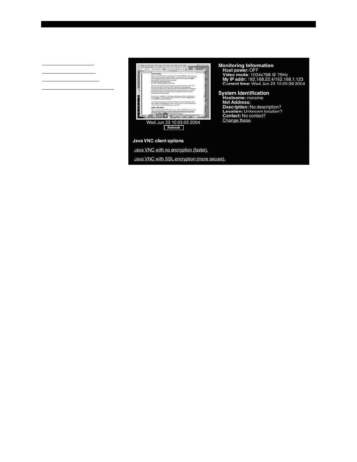
The Home Screen
The Home screen serves two functions. First, it is a place to check the status of the unit, view
essential system information, and
capture screen shots from the
managed computers. Second, it is
where you can start the integrated
Java VNC client to interact with the
managed computers by clicking on
the large screen shot or choosing one
of the VNC client links.
The Admin/Setup Screen
This is the menu that will allow you
to access all the features you will
need to perform an initial
configuration of the Server Remote
Control. Each of the options is
explained in detail here.

SVx41HDI Series Server Remote Control: Instruction Guide
7
Network Configuration (IP address. netmask, gateway)
Dynamic Host
Configuration Protocol
(DHCP)
Automatic network
configuration using DHCP
is: Enabled/Disabled.
This feature applies to the
LAN port on the rear panel,
and is enabled by default.
When enabled, the unit will
automatically configure
itself with an IP address
when a DHCP server is present. When disabled, the LAN port will use the values
assigned to it on the IP Addresses and Routing table below.
IP Addresses and Routing
This table allows you to assign IP information for the LAN port. If you are using DHCP,
the values for the LAN port will be filled in automatically and any changes made will not
affect the setup.
Domain Name Server (optional)
This section allows you to specify DNS servers and the default DNS domain suffix in use
on the network. If DHCP is enabled, some of these values may be supplied
automatically.
Commit Network Changes
Clicking the Commit button applies any changes made on the page to the configuration,
but leaves the old settings
active until the next time
the unit restarts. Clicking
Make changes effective
now applies the changes
and restarts the unit so the
new settings take effect
immediately.
User accounts: add, delete and
change passwords
This menu will allow you to add
accounts other than admin to the
system. These accounts will not
have the authority to change settings, but can access the Web interface and log in the VNC
SVx41HDI Series Server Remote Control: Instruction Guide
8
console. Selecting Delete permanently removes the user from the system. If you enter values
for a user that does not already exist under Edit User Details, the system will create that user for
you when you click Record changes. If the user already exists, you will change the password
for that user.
Change system identification
Provides details about this unit that will be available to DHCP servers, SNMP agents, and
VNC clients. While these values do not affect the operation of the unit, they make it
easier to manage on the network.
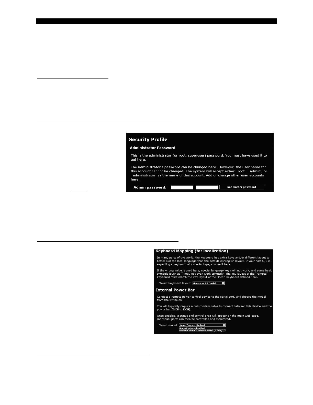
Security policy, internal firewall and admin password.
This menu allows you to
configure a number of
settings, including
changing the default
password for admin
(recommended). Read and
consider the comments
and instructions on this
menu before making any
changes, as changing these features could make the unit inaccessible through Web
configuration (i.e. due to firewall filtering). Note that any password changes you make
will have to be entered in duplicate to prevent the chance for error.
Setup compatibility with host system, external power bar.
This menu allows you to configure
the unit for use with products such as
the StarTech.com Serial Control
Power Switch and locale-specific
items such as a non-English
keyboard. When the StarTech.com 8-
outlet Serial Power Console Switch is
selected as the external power bar,
additional menu choices will appear
on the main page of the Web
interface. See the documentation for
the StarTech.com Serial Control
Power Switch for more details on how to access and configure this feature.
Port numbers to be used for different services.

SVx41HDI Series Server Remote Control: Instruction Guide
9
Takes you to the Ports menu (see below).
Debug network setup values and routing.
Takes you to the Status menu (see below).
SNMP agent setup and configuration.
This menu allows you to configure the unit so it can be recognized and managed using
industry-standard Simple Network Management Protocol software.
RADIUS authentication setup.
The RADIUS server requires the IP
address, the UDP port number
(1812 - default or 1645) and the
shared secret. The shared secret is
used to encrypt communications
and corresponds to a shared
password for the RADIUS server
and the client machine. Two
additional servers may be defined
for backup purposes. Each server
will be tried in order, using the
indicated number of retries and
timeout period, which are configurable on the same page. Remember to enable RADIUS after
configuring it. While RADIUS authentication is enabled, the locally defined accounts on the
KVM control over IP module will not be used, except for the SSH login. However, if a user
name of the form “name.local” is given at the RADIUS prompt, the system will use “name”;
check the password locally, and skip RADIUS authentication. Delete all local accounts to avoid
this behavior. When connecting via VNC, a login screen is generated that asks for a RADIUS
username and password.
Additional RADIUS challenges
may be demanded depending on
the RADIUS server in use. This
allows operation with hardware
tokens and other advanced
authentication devices.
External Serial consoles setup and
control.
The StarTech.com Server Remote
Control product line offers a

SVx41HDI Series Server Remote Control: Instruction Guide
10
number of additional accessories that enhance the flexibility of this product, called R-Port
Devices. This screen allows you to view and manage these devices. For more information on
accessories available for the Server Remote Control see Appendix F, contact your local dealer or
visit www.startech.com for more information.
Set date and time.
Allows you to set the unit to local or Universal Coordinated Time (GMT).
Firmware and flash memory
management.
The firmware on the Serial
Remote Control is field
upgradeable. To upgrade to
another version, login as
admin.
Auto Self Upgrade
The unit includes an
innovative feature allowing
the unit to upgrade itself
over the Internet. Simply
click on the button labeled
Upgrade to latest and the
module will go out to the Internet and download the latest version of the system firmware
and then install it. If the module cannot access the Internet directly (perhaps due to a Web
proxy or other firewalls), then a page will be shown that causes your browser to
download the required file. Save this file to disk and then upload it as described in the
next section, Manual Upload. The main FPGA is upgraded separately, and has its own
Upgrade button. This file is unique for each unit, so it must be done in this manner.
If you have multiple units to upgrade, you may choose the Get latest version button that
will not attempt to upgrade the unit directly, but will instead fetch the required file. This
file can be uploaded to multiple units manually. You may also choose Reboot Myself at
the bottom of the screen to restart the unit without powering on and off.
Manual Upload
Enter the name of the firmware file that you received from StarTech.com into the field
provided (or use the Browse... button). Press Start Upload and wait until a successful
upload message is shown.
NOTE: Remember the following during the firmware upgrade…
• Do NOT turn off power to unit before this operation completes successfully. It
may take several minutes to write to flash memory.
SVx41HDI Series Server Remote Control: Instruction Guide
11
• The unit will sometimes reboot as part of the upgrade procedure, depending
on which system component is upgraded. You will have to reconnect and re-
login in those cases.
• Wait at least two minutes after pressing Start. Do not assume the upload did
not work. There is no status indicator bar to show the progress of the upload.
The upload could simply be slow.
• Each file that is distributed upgrades a different component of the system.
Therefore, be sure to apply all files you are given as part of an upgrade. The
system knows what to do with each file you give it, and they are checked for
validity before being applied.
Software Options Upgrade
Certain firmware features may be offered separately from the base unit, in order to reduce
the initial cost for the Server Remote Control.
NOTE: If you wish to upgrade after the system is in operation, go to the Manage
Firmware page and scroll down to the section entitled Purchase Options.
Look for a unique code, like the following one:
4-C80C-B960-1-0
If you provide this code to the technical support department, they can give you an unlock
code that will open any feature you request. Types in the code provided, exactly, into the
area provided and click “Submit”. The new features opened by the code will be enabled
immediately, but you may need to reboot the unit to begin using certain features.
Status Screen
This screen displays a system security log, various system settings, and the ability to generate a
copy of the system configuration in plain text format.
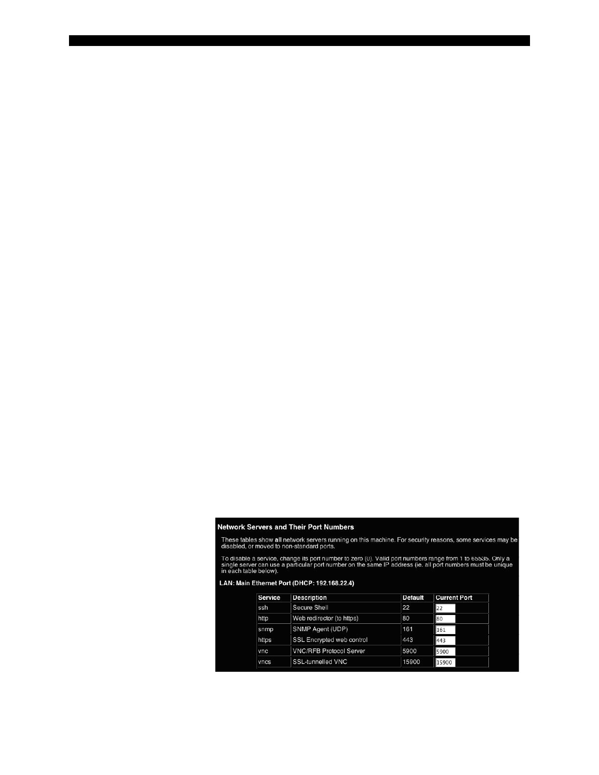
Port Numbers
This table allows you to change TCP port values for services available on the unit. By default,
they are factory-set to common Internet values. You may wish to enhance security by disabling
services that you will not
use with the unit. To disable
a service, change its port
number to 0. When you
have made any necessary
changes, click Commit
Changes to use the settings
the next time the unit
restarts. To force the unit to
restart immediately, click
Restart Servers.

SVx41HDI Series Server Remote Control: Instruction Guide
12
Help! Menu
Provides a FAQ (Frequently Asked Questions) listing to assist you with the features and
operation of the Server Remote Control.
Copyright Menu
Provides the Terms of Use and other information related to the firmware and software on the
unit.
Site map Menu
This menu provides a hyperlinked directory of each setting available on the Web configurator.
Logout
Securely logs you out from your Web session on the Server Remote Control.
Using the Terminal Interface via Serial Port
The terminal interface you can access via the serial port permits the configuration of the basic
settings of the unit. While not intended to be a substitute for the Web interface, it does allow you
to configure some of the same functions. The following menu list describes the options that can
be modified through the terminal interface. Note that you must use the W option to confirm and
apply any changes you make before exiting the terminal session.

SVx41HDI Series Server Remote Control: Instruction Guide
13
-----------------------------------
Server Remote Control Network Setup
-----------------------------------
NOTE: This interface is used to set network parameters and perform
certain recovery procedures, but the majority of setup and
configuration can only be done using the web interface.
Primary Ethernet Port (LAN) (00:0e:c5:00:09:94)
D.H.C.P.: Disabled
IP Address: 172.19.2.21
Netmask: 255.255.0.0
Gateway: 172.19.1.7
Broadcast: 172.19.255.255
Machine name: noname
Commands (press one key, then Enter):
D - Enable DHCP for dynamic IP address.
I - Set IP address.
N - Set netmask.
G - Set default gateway.
B - Set broadcast address (optional).
M - Change machine name (DHCP client name).
H - Reset/disable firewall, TCP ports, SNMP, RADIUS.
F - Reset everything to factory defaults.
S - Change system admin password.
P - Send ICMP ping packets (testing purposes).
? - Show TCP/IP ports and servers enabled.
R - Revert to current settings (undo changes).
W - Commit changes to configuration.
Choice:
Accessing the VNC Interface
There are three ways to communicate with the Server Remote Control in order to control the
managed computers:
• Web interface: The integrated Web server includes a Java-based VNC client. This
allows easy browser-based remote control.
• Native VNC client: There are several third-party software programs that use the
standard VNC protocol, available in open source and commercial VNC clients.
• SSH access: By default, there is a standard SSH server running on port 22 (the
standard SSH port). Once connected via SSH, the VNC traffic is tunneled through the
SSH connection and encrypts the VNC session. Each method will be discussed
briefly in the following section. The type of encryption method or client used is not
critical.
NOTE: The first time the Server Remote Control is accessed, it defaults to the PC 1 port on the
master switch as the default managed client to display. If there is no computer/slave KVM
connected to that port, you will see a blank screen until you switch to a port with an active
managed computer. For future sessions, the unit will default to the last port accessed when
beginning a VNC session, assuming the unit has not been upgraded or reset.
Web Interface
The Java-based VNC client that is integrated into the unit’s interface requires a browser with
cookies and JavaScript enabled. To start the Java VNC client, login to the Web configuration
SVx41HDI Series Server Remote Control: Instruction Guide
14
interface and click on the thumbnail of the desktop on the Home menu, or follow one of the two
links on that page:
Java VNC with no
encryption (faster).
Java VNC with SSL
encryption (more secure).
You may need to upgrade
your Java support in your
browser; however, most
modern browsers come with
a version of Java that is
compatible with this
application.
The Java VNC client makes
a connection back to unit
over port 5900 (by default) or 15900, if encrypted. The encrypted connection is a standard SSL
(Secure Socket Layer) encrypted link that encrypts all data from the session, including the actual
video pictures.
Because Java is considered a “safe” programming language, the Java VNC client has some
limitations. Certain special keystrokes cannot be sent, such as Scroll Lock on the keyboard.
This client software requires the use of Java 2 (JRE 1.4) to enable features like wheel mouse
support. Sun Microsystems’s Java site, www.java.com, is an excellent resource to ensure your
browser and operating system is up-to-date.
Native VNC Client
This system implements the VNC protocol, so any off the shelf VNC client can be used. There
are over 17 different VNC clients available and they should all work with this system. This
system automatically detects and makes use of certain extensions to the basic RFB protocol that
is provided by the better VNC clients.
The best client currently is TightVNC (www.tightvnc.com). Binaries are available for Windows,
Linux, MacOS and many versions of Unix. Source code for all clients is available there too. This
version of VNC is being actively developed. The authoritative version of VNC is available from
RealVNC (www.realvnc.com). This source base is the original version of VNC, maintained by
the original developers of the standard. For a commercial, supported version of VNC, you should
consider TridiaVNC (www.tridiavnc.com). Their version of VNC is a superset of TightVNC and
contains a number of enhancements for use in a larger corporate environment.
NOTE: Some native VNC clients may require a flag or setting indicating they should use
BGR233 encoding by default. If this flag is not set, you may see a garbled picture and the client
will fail. The Unix versions of VNC require the flag -bgr233. For examples on using this flag,
review the commands in the following section.

SVx41HDI Series Server Remote Control: Instruction Guide
15
SSH Tunnel (with Native VNC client)
If you are using openssh, here is the appropriate Unix command to use, based on the default
settings on a machine at 10.0.0.34:
ssh -f -l admin -L 15900:127.0.0.1:5900 10.0.0.34 sleep 60
vncviewer -bgr233 127.0.0.1::15900
Notes:
• A copy of these commands, with appropriate values filled in for your current system
setting, is provided in the on-line help page. This allows you to “cut-and-paste” the
required commands accordingly.
• You have 60 seconds to type the second command before the SSH connection will be
terminated.
• The port number “15900” is arbitrary in the above example and can be any number
(1025...65535). It is the port number used on your client machine to connect your
local SSH instance with the VNC client. If you want to tunnel two or more systems,
you will need to use a unique number for each instance on the same SSH client
machine.
• Some Unix versions of the VNC client have integrated SSH tunneling support. Some
clients require your local user id to be the same as the userid on the system. Use a
command like this:
vncviewer -bgr233 -tunnel 10.0.0.34:22
Using the VNC Menu
One of the unique features of this product is the VNC menu system. Whenever you see a window
with a dark blue background and grey edges, this window has been inserted into the VNC
datastream so that it is effectively laid over the existing video. These menus allow you to control
the many features of the KVM without using the Web interface or a custom client.
The commands you send through this interface (i.e. restart) will be sent to the managed
computer currently active on the Server Remote Control. It is advisable to verify which
managed computer is active before making any changes. We strongly recommend you
thoroughly familiarize yourself with the information here and in the next section
(“Accessing KVM Features”) before undertaking any critical tasks through the VNC
interface.
SVx41HDI Series Server Remote Control: Instruction Guide
16
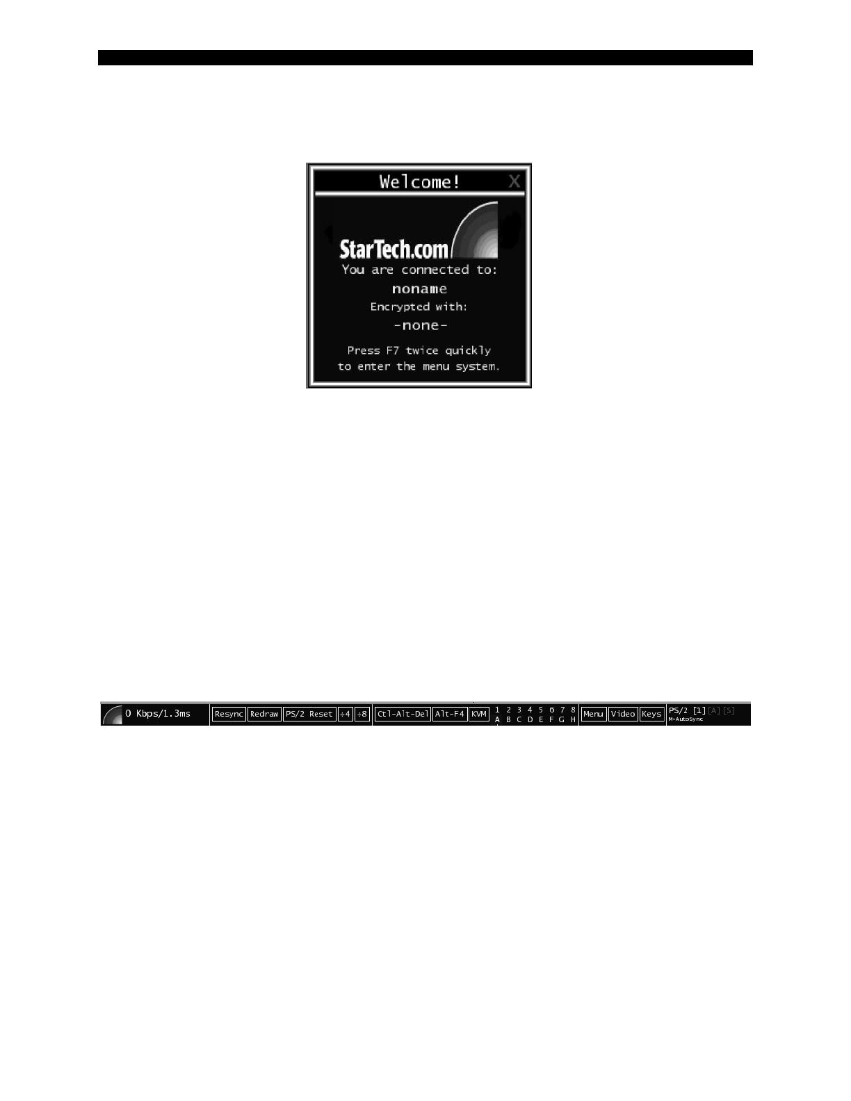
Welcome Window
When you initially connect to the system, a window similar to this one will be shown.
This tells you which system you are controlling, what encryption algorithm was used and what
key strength is currently in effect. Click anywhere inside the window to clear it, or wait ten
seconds.
Bribar Feature
Along the bottom of the VNC screen is a dark blue bar with various buttons. We call this feature
“the Bribar”. Its purpose is to show a number of critical status values and to provide shortcuts to
commonly used features.
Here is a snapshot of what it may look like. There will be slight differences based on optional
features and system configuration. Starting from the left side of the Bribar, each feature and its
function is outlined below.
Bandwidth: Indicates current average bandwidth coming out of the KVM control over IP
module. The second number measures round trip time (RTT) of the connection when it
was first established.
Resync: Re-aligns the remote and local mouse points so they are on top of each other.
Redraw: Redraws the entire screen contents; occurs immediately.
PS/2 Reset: Resets the PS/2 keyboard and mouse emulation. Useful to recover failed
mouse and/or keyboard connections.
÷4, ÷8: Switches to thumbnail mode, at indicated size.
Ctrl-Alt-Del: Sends this key sequence to the host. Works immediately.
Alt-F4: Sends the key sequence to host (closes windows).
1~8, A~H: Switches the current view to the specified KVM port. This function works
for the master unit only. Use the KVM menu (see below) to access KVM functions on a
slaved unit.

SVx41HDI Series Server Remote Control: Instruction Guide
17
KVM: Sends the KVM “hotkey” sequence. This function is equivalent to pressing the
left control key on the keyboard three times to access the KVM on-screen display.
Menu: Shows the main menu.
Video: Shows the video-tuning menu where the picture quality can be adjusted.
Keys: Shows the VirtKeys menu, which allows you to simulate pressing special keys
such as the Windows key or complex multi-key sequences.
PS/2: This area will show either PS/2 (as in the example) or USB to indicate if keyboard
and mouse are being emulated via USB connection or PS/2 signals.
M-Autosync: Shows when the mouse autosync feature is enabled. When active, the unit
will automatically attempt to match the positions of the remote mouse pointer and the
VNC session’s (local) mouse pointer on the screen (recommended).
[1][A][S]: These flags show the state of the keyboard lights, NumLock, ShiftLock and
ScrollLock respectively.
X: Click this button to close the Bribar and hide it. This can be very useful on a client
machine whose screen-size is the same as the remote machine. No vertical screen space is
wasted with the Bribar. Use double-F7 to start the main menu, then click on Bribar to
restore the feature.
Other Items: If the server's screen is larger than 1024x768, additional buttons will be
shown to the right of the above listed items. These are all keyboard shortcuts and are
duplicated in the Keys menu.
/