Sony XM-S400D Operating instructions

Category
Car audio amplifiers
Type
Operating instructions
4-581-373-41(1)
XM-S400D
4 Channel Class-D
Amplifier
The warranty for this product is included in this manual
(page 13, 14).
La garantie de ce produit est inclus dans le présent manuel
(page 12).
Owner’s Record
The model and serial numbers are located on the bottom of the
unit.
Record the serial number in the space provided below.
Refer to these numbers whenever you call upon your Sony dealer
re
garding this product.
Model No. XM-S400D
Serial No.
Operating Instructions
GB
Mode d’emploi
FR
Manual de instrucciones
ES
2GB
Warning
FOR THE CUSTOMERS IN THE USA. NOT
APPLICABLE IN CANADA, INCLUDING IN THE
PROVINCE OF QUEBEC.
POUR LES CLIENTS AUX ÉTATS-UNIS. NON
AP
PLICABLE AU CANADA, Y COMPRIS LA
PROVINCE DE QUÉBEC.
This equipment has been tested and found to
comply with the limits for a Class B digital device,
pursuant to Part 15 of the FCC Rules.
These limits are designed to provide reasonable
p
rotection against harmful interference in a
residential installation. This equipment
generates, uses, and can radiate radio frequency
energy and, if not installed and used in
accordance with the instructions, may cause
harmful interference to radio communications.
However, there is no guarantee that interference
wi
ll not occur in a particular installation. If this
equipment does cause harmful interference to
radio or television reception, which can be
determined by turning the equipment off and
on, the user is encouraged to try to correct the
interference by one or more of the following
measures:
R
eorient or relocate the receiving antenna.
I
ncrease the separation between the
equipment and receiver.
C
onnect the equipment into an outlet on a
circuit different from that to which the receiver
is connected.
C
onsult the dealer or an experienced radio/TV
technician for help.
You are cautioned that any changes or
m
odifications not expressly approved in this
manual could void your authority to operate this
equipment.
3GB
Features
Maximum power output of 100 W per channel (at
4 Ω).
Buil
t-in LP (low-pass) filter and HP (high-pass)
filter.
P
rotection circuit and indicator provided.
D
irect connection can be made with the speaker
output of your car audio unit if it is not equipped
with the line output (High level input connection).
H
i-level Sensing Power On feature allows this unit
to be activated without the need for a REMOTE
connection.
Cl
ass-D Technology* is supported.
* Class-D Technology
The Class-D Technology is a method to convert and
a
mplify music signals with MOSFETs to high speed
pulse signals. Furthermore, it features high efficiency
and low heat generation.
Table of Contents
Warning . . . . . . . . . . . . . . . . . . . . . . . . . . . . . . . . . . . 2
Features . . . . . . . . . . . . . . . . . . . . . . . . . . . . . . . . . . . 3
Operation
Location and Function of Controls . . . . . . . . . . . . . . 4
Installation and Connections
Parts for Installation and Connections. . . . . . . . . . . 5
Installation . . . . . . . . . . . . . . . . . . . . . . . . . . . . . . . . . 5
Connections . . . . . . . . . . . . . . . . . . . . . . . . . . . . . . . . 6
Power Connections . . . . . . . . . . . . . . . . . . . . . . . 6
Input Connections . . . . . . . . . . . . . . . . . . . . . . . . 7
Speaker Connections . . . . . . . . . . . . . . . . . . . . . 9
Additional Information
Precautions . . . . . . . . . . . . . . . . . . . . . . . . . . . . . . . 10
Maintenance . . . . . . . . . . . . . . . . . . . . . . . . . . . . . . 10
Fuse Replacement. . . . . . . . . . . . . . . . . . . . . . . 10
Specifications. . . . . . . . . . . . . . . . . . . . . . . . . . . . . . 11
Troubleshooting . . . . . . . . . . . . . . . . . . . . . . . . . . . 12
Important notice
The warranty for this product is included in this
manual (page 13, 14). Keep this manual for future
use.
4GB
Location and Function of Controls
POWER/PROTECT indicator
Lights up in green during operation.
If the protection circuit activates, the POWER/
PROTECT indicator flashes. For details, see
“Troubleshooting” (page 12).
SIGN
AL INPUT connector
Can be connected with the supplied RCA input
co
rd or high level input cord.
INP
UT SELECT switch
Sets the input signal to “2CH” or “4CH.
R
EAR LPF (low-pass filter) switch
Sets the low-pass filter (LPF) to “ON” or “OFF.
FR
ONT HPF (high-pass filter) switch
Sets the high-pass filter (HPF) to “ON” or “OFF.”
S
lit for the supplied bracket
Insert the bracket and secure with the screw to
m
ount the unit on the mounting board or flat
surface.
F
use holder (15A)
When replacing the fuse, be sure to use one
w
ith 15 A.
PO
WER/OUTPUT connector
Can be connected with the supplied power
c
onnection cable.
Operation
5GB
Parts for Installation and
Connections
This parts list does not include all the package
contents.
Installation
Mount the unit on a flat surface.
M
ount the unit where
T
he unit will not interfere with the normal
movements of the driver.
T
he unit will not be exposed to direct sunlight
or hot air from the heater.
The
unit will not come into contact with a
driver/passengers or materials in your car since
the unit becomes hot during use.
Do
not install the unit under the floor carpet,
where the heat dissipation from the unit will be
considerably impaired.
Mounting the unit
Prepare a mounting board that is thicker than 20
mm (
13
/16 in) since the supplied mounting screws
are all 20 mm (
13
/16 in) long. The unit can also be
mounted on the flat surface of your car without a
mounting board.
1 Insert the supplied mounting brackets
into the slits of the unit and secure them
with the supplied bracket screws .
2 Place the unit on the mounting board
and mark the two screw hole positions.
3 Drill a 3 mm (
1
/8 in) pilot hole at each
mark on the mounting board.
Installation and Connections
Main unit
×1
Power connection cable
×1
RCA input cord
×1
High level input cord
×1
Bracket
×2
Bracket screw
ø 2.6 mm × 6 mm
(
1
/8 in ×
1
/4 in)
×2
Mounting screw
ø 4 mm × 20 mm
(
3
/16 in ×
13
/16 in)
×2
6GB
4 Place the unit on the mounting board
and secure it with the supplied mounting
screws .
Connections
Before making any connections, disconnect the
ground (earth) terminal of the car battery to avoid
short circuits.
I
f your car is equipped with a computer system for
navigation or some other purpose, disconnecting
the ground (earth) wire from the car battery may
damage the computer memory. Leaving the
ground (earth) wire connected and disconnecting
the +12 V power supply wire until all the other
wires have been connected may prevent short
circuits.
Be su
re to use speakers with an adequate power
rating. If you use small capacity speakers, they
may be damaged.
Do
not connect the terminal of the speaker
system to the car chassis, and do not connect the
terminal of the right speaker with that of the
left speaker.
In
stall the input and output cords away from the
power supply wire. Running them close together
may generate interference noise.
C
onnect the +12 V power supply wire only after all
the other wires have been connected and the
settings on this unit have been made.
B
e sure to connect the ground (earth) wire of the
unit securely to a metal point of the car. A loose
connection may cause a malfunction of the
amplifier.
B
e sure to connect the remote control wire of the
car audio unit to the remote input (REM) wire of
the supplied power connection cable.
W
hen using a car audio unit without a remote
output for the amplifier, connect the remote input
(REM) wire of the supplied power connection
cable to the accessory power supply.
U
se a power supply wire with a fuse (15 A)
attached.
All
power wires connected to the positive battery
post should be fused within 450 mm (17
3
/4 in) of
the battery post, and before they pass through
any metal.
M
ake sure that the car’s battery wires connected
to the car (ground (earth) to chassis) are of a wire
gauge at least equal to that of the main power
wire connected from the battery to the amplifier.
D
uring full-power operation, a current of more
than 15 A will run through the system. Therefore,
make sure that the wires to be connected to the
+12 V and GND wires of this unit are at least 14-
G
auge (AWG-14) or have a sectional area of more
than 2 mm² (
3
/32 in²).
Power Connections
7GB
Making power connections
Connect the supplied power connection cable to
the POWER/OUTPUT connector on the unit.
*1 Ground (earth) to chassis.
*2 If you have the factory original or some other car
audi
o unit without a remote output for the amplifier,
connect the remote input (REM) wire of the supplied
power connection cable to the accessory power
supply. With the high level input connection, the car
audio unit can also be activated without need for a
REMOTE connection. However, this function is not
guaranteed for all car audio units.
Set the INPUT SELECT switch to “2CH” or “4CH”
according to the input connection.
Also, refer to the manual supplied with your car
a
udio unit for further details.
Line input connection
Set the INPUT SELECT switch to “4CH” with the
speaker connection (page 9).
Line input connection
Set the INPUT SELECT switch to “2CH” with the
speaker connection (page 9).
to a metal point of the car
less than 450 mm (17
3
/4 in)
Fuse (15 A)
+12 V car battery
Car audio
Input Connections
Car audio
Car audio
8GB
High level input connection
Set the INPUT SELECT switch to “4CH” with the
speaker connection (page 9).
High level input connection
Set the INPUT SELECT switch to “2CH” with the
speaker connection (page 9).
Gray
Gray/Striped
Front right speaker output
White
White/Striped
Front left speaker output
Car audio
Purple
Purple/Striped
Rear right speaker output
Rear left speaker output
Green
Green/Striped
Gray
Gray/Striped
White
White/Striped
Front right speaker output
Front left speaker output
Car audio
9GB
Set the REAR LPF switch and FRONT HPF switch to
“ON” or “OFF” according to the speaker system.
Also, refer to the manual supplied with your
s
peakers for further details.
4-speaker system
Set with the input connection (page 7) or
(page 8).
2-way system
Set with the input connection (page 7) or
(page 8).
Note
In this system, the volume of the subwoofer will be
c
ontrolled by the car audio unit fader control.
Speaker Connections
White
White/Striped
Gray
Gray/Striped
Green
Green/Striped
Purple
Purple/Striped
Front speakers (min. 4 Ω)
Rear speakers (min. 4 Ω)
White
White/Striped
Gray
Gray/Striped
Green
Green/Striped
Purple
Purple/Striped
Full range speakers (min. 4 Ω)
Subwoofers (min. 4 Ω)
10GB
Precautions
This unit is designed for negative ground (earth)
12 V DC operation only.
Us
e speakers with an impedance of 4 Ω to 8 Ω.
Do no
t connect any active speakers (with built-in
amplifiers) to the unit. Doing so may damage the
active speakers.
Avo
id installing the unit in areas subject to:
H
igh temperatures such as from direct sunlight
or hot air from the heater
Rai
n or moisture
Du
st or dirt
In
clined surface
Di
rect contact with a driver/passengers.
I
f your car is parked in direct sunlight and there is
a considerable rise in temperature inside the car,
allow the unit to cool down before use.
W
hen installing the unit horizontally, be sure not
to cover the unit with the floor carpet, etc.
I
f this unit is placed too close to the car audio unit
or antenna (aerial), interference may occur. In this
case, relocate this unit away from the car audio
unit or antenna (aerial).
I
f no power is being supplied to the car audio
unit, check the connections.
T
his unit employs a protection circuit* to protect
the transistors and speakers if the amplifier
malfunctions. Do not attempt to test the
protection circuits by covering the unit or
connecting improper loads.
Do no
t use the unit on a weak battery as its
optimum performance depends on a good power
supply.
F
or safety, keep your car audio unit volume
moderate so that you can still hear other sounds.
* Protection circuit
This amplifier is provided with a protection circuit that
o
perates in the following cases:
Wh
en the unit overheats
Wh
en a DC current is generated
W
hen the speaker terminals are short-circuited.
If a protection circuit is activated, the POWER/
P
ROTECT indicator will flash. For details, see
“Troubleshooting” (page 12).
If you have any questions or problems concerning
your unit that are not covered in this manual,
please consult your nearest Sony dealer.
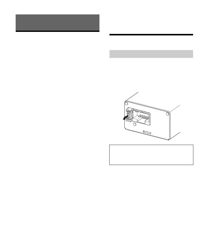
Maintenance
When replacing the fuse, be sure to use one
matching the amperage stated above the fuse
holder. If the fuse blows, check the power
connection and replace the fuse. If the fuse blows
again after replacement, there may be an internal
malfunction. In such a case, consult your nearest
Sony dealer.
Additional Information
Fuse Replacement
Warning
Never use a fuse with an amperage rating
exceeding the one supplied with the unit as this
could damage the unit.
11GB
Specifications
FOR THE CUSTOMERS IN THE USA. NOT
APPLICABLE IN CANADA, INCLUDING IN THE
PROVINCE OF QUEBEC.
POUR LES CLIENTS AUX ÉTATS-UNIS. NON
AP
PLICABLE AU CANADA, Y COMPRIS LA
PROVINCE DE QUÉBEC.
AUDIO POWER SPECIFICATIONS
CEA2006 Standard
Power Output: 45 Watts RMS × 4 at
4 Ohms < 1% THD+N
SN Ratio: 83 dBA
(reference: 1 Watt into 4 Ohms)
Circuit system
OTL (output transformerless) circuit,
Pulse power supply
Inputs
RCA pin jacks,
High level input connector
Input level
1 V (RCA pin jacks),
8 V (High level input)
Outputs
Speaker terminals
Speaker impedance
4 Ω – 8 Ω
Maximum output
4 Speakers: 100 W × 4 (at 4 Ω)
Rated output
(supply voltage at 14.4 V, 1 kHz, 1% THD)
4 Speakers: 45 W × 4 (at 4 Ω)
Frequency response
20 Hz – 20 kHz ( dB)
Harmonic distortion
0.08% or less (at 1 kHz, 4 Ω)
Low-pass filter
120 Hz, 12 dB/oct
High-pass filter
120 Hz, 12 dB/oct
Power requirements
12 V DC car battery (negative ground (earth))
Power supply voltage
10.5 V – 16 V
Current drain
At rated output: 15 A (4 Ω, 45 W × 4)
Remote input: 1 mA
Dimensions
Approx. 162.8 mm × 37.3 mm × 62.6 mm
(6
1
/2 in × 1
1
/2 in × 2
1
/2 in) (w/h/d) not incl.
projecting parts and controls
3
7.3 mm (1
1
/2 in)
62
.6 mm (2
1
/2 in)
31.3 m
m (1
1
/4 in)
16
2.8 mm (6
1
/2 in)
17
6.8 mm (7 in)
Mass
Approx. 0.46 kg (1
1
/64 lb) not incl. accessories
Package contents
Main unit (1)
Parts for installation and connections (1 set)
Your dealer may not handle some of the above
l
isted accessories. Please ask the dealer for detailed
information.
Design and specifications are subject to change
w
ithout notice.
+0.5
3.0
12GB
Troubleshooting
The following checklist will assist in the correction
of most problems which you may encounter with
your unit. Before going through the checklist below,
refer to the connection and operating procedures.
The POWER/PROTECT indicator does not light up.
The fuse is blown.
Rep
lace the fuse with a new one.
T
he ground (earth) wire is not securely
connected.
F
asten the ground (earth) wire securely to a
metal point of the car.
T
he voltage going into the remote input (REM)
wire is too low.
T
urn on the car audio unit if it is not turned on.
Us
e a relay if the system employs too many
amplifiers.
Che
ck the battery voltage (10.5 V – 16 V).
The POWER/PROTECT indicator flashes quickly
(once every 0.2 seconds) and the unit turns off
automatically.
The speaker outputs are short circuited.
T
ake out any media from the car audio unit and
turn the connected equipment off, then
determine the cause of the short circuits.
T
he speaker cord and ground (earth) wire are not
securely connected.
T
ake out any media from the car audio unit and
turn the connected equipment off, then
connect the speaker cord securely and fasten
the ground (earth) wire to a metal point of the
car.
T
he unit has overheated.
W
ait until the unit cools down.
Chec
k whether the impedance of the
connected speakers is lower than 4 Ω.
The POWER/PROTECT indicator flashes slowly
(once every second) and sound becomes low.
The unit has overheated and thermal protector is
activated.
Tu
rn the volume down.
The unit becomes abnormally hot.
Use speakers with a suitable impedance of 4 Ω -
8 Ω.
Ma
ke sure to place the unit in a well ventilated
location.
Alternator noise is heard.
The power connecting wires are installed too
close to the RCA pin cords.
K
eep the wires away from the cords.
T
he ground (earth) wire is not securely
connected.
F
asten the ground (earth) wire securely to a
metal point of the car.
The filter switch is set to the wrong position.
When connecting the subwoofer (2-way system
connection), set the REAR LPF switch to “ON”
(page 9).
W
hen connecting the full range speaker (2-way
system connection), set the FRONT HPF switch to
“ON” (page 9).
W
hen connecting the front speakers and the rear
speakers (4-speaker system connection), set the
FRONT HPF and REAR LPF switches to “OFF”
(page 9).
If these solutions do not help improve the situation,
c
onsult your nearest Sony dealer.
http://www.sony.net/
©2016 Sony Corporation Printed in Thailand
  • Page 1 1
  • Page 2 2
  • Page 3 3
  • Page 4 4
  • Page 5 5
  • Page 6 6
  • Page 7 7
  • Page 8 8
  • Page 9 9
  • Page 10 10
  • Page 11 11
  • Page 12 12
  • Page 13 13
  • Page 14 14
  • Page 15 15
  • Page 16 16
  • Page 17 17
  • Page 18 18
  • Page 19 19
  • Page 20 20
  • Page 21 21
  • Page 22 22
  • Page 23 23
  • Page 24 24
  • Page 25 25
  • Page 26 26
  • Page 27 27
  • Page 28 28
  • Page 29 29
  • Page 30 30
  • Page 31 31
  • Page 32 32
  • Page 33 33
  • Page 34 34
  • Page 35 35
  • Page 36 36
  • Page 37 37
  • Page 38 38
  • Page 39 39
  • Page 40 40

Sony XM-S400D Operating instructions

Category
Car audio amplifiers
Type
Operating instructions

Ask a question and I''ll find the answer in the document

Finding information in a document is now easier with AI