Basler racer GigE Owner's manual
- Category
- Security cameras
- Type
- Owner's manual

Basler racer
USER’S MANUAL FOR GigE VISION CAMERAS
Document Number: AW001183
Version: 08 Language: 000 (English)
Release Date: 29 April 2019

For customers in the USA
This equipment has been tested and found to comply with the limits for a Class A digital device,
pursuant to Part 15 of the FCC Rules. These limits are designed to provide reasonable protection
against harmful interference when the equipment is operated in a commercial environment. This
equipment generates, uses, and can radiate radio frequency energy and, if not installed and used
in accordance with the instruction manual, may cause harmful interference to radio
communications. Operation of this equipment in a residential area is likely to cause harmful
interference in which case the user will be required to correct the interference at his own expense.
You are cautioned that any changes or modifications not expressly approved in this manual could
void your authority to operate this equipment.
The shielded interface cable recommended in this manual must be used with this equipment in
order to comply with the limits for a computing device pursuant to Subpart B of Part 15 of FCC
Rules.
For customers in Canada
This apparatus complies with the Class A limits for radio noise emissions set out in Radio
Interference Regulations.
Pour utilisateurs au Canada
Cet appareil est conforme aux normes Classe A pour bruits radioélectriques, spécifiées dans le
Règlement sur le brouillage radioélectrique.
Life support applications
These products are not designed for use in life support appliances, devices, or systems where
malfunction of these products can reasonably be expected to result in personal injury. Basler
customers using or selling these products for use in such applications do so at their own risk and
agree to fully indemnify Basler for any damages resulting from such improper use or sale.

Observe the following items
Do not remove the camera’s product label that contains the serial number.
Do not open the housing and do not touch the internal components, you may damage them.
Prevent ingress or insertion of foreign substances into the camera housing. If operated with
any foreign substances inside, the camera may fail or cause a fire.
Do not operate the camera in the vicinity of strong electromagnetic fields. Avoid electrostatic
charging.
Transport the camera in its original packaging only. Do not discard the packaging.
All material in this publication is subject to change without notice and is copyright
Basler AG.

Contacting Basler Support Worldwide
Europe, Middle East, Africa
Basler AG
An der Strusbek 60–62
22926 Ahrensburg
Germany
Tel. +49 4102 463 515
Fax +49 4102 463 599
support.europe@baslerweb.com
The Americas
Basler, Inc.
855 Springdale Drive, Suite 203
Exton, PA 19341
USA
Tel. +1 610 280 0171
Fax +1 610 280 7608
Asia-Pacific
Basler Asia Pte. Ltd.
35 Marsiling Industrial Estate Road 3
#05–06
Singapore 739257
Tel. +65 6367 1355
Fax +65 6367 1255
support.asia@baslerweb.com
www.baslerweb.com

AW00118308000 Table of Contents
Basler racer GigE i
Table of Contents
1 Specifications, Requirements, and Precautions . . . . . . . . . . . . . . . . . . . . . . . . 1
1.1 Intended Use . . . . . . . . . . . . . . . . . . . . . . . . . . . . . . . . . . . . . . . . . . . . . . . . . . . . . . . . . 1
1.2 Authorized Users . . . . . . . . . . . . . . . . . . . . . . . . . . . . . . . . . . . . . . . . . . . . . . . . . . . . . . 1
1.3 Models . . . . . . . . . . . . . . . . . . . . . . . . . . . . . . . . . . . . . . . . . . . . . . . . . . . . . . . . . . . . . . 2
1.4 General Specifications . . . . . . . . . . . . . . . . . . . . . . . . . . . . . . . . . . . . . . . . . . . . . . . . . . 3
1.5 Accessories . . . . . . . . . . . . . . . . . . . . . . . . . . . . . . . . . . . . . . . . . . . . . . . . . . . . . . . . . . 9
1.6 Spectral Response . . . . . . . . . . . . . . . . . . . . . . . . . . . . . . . . . . . . . . . . . . . . . . . . . . . . 10
1.7 Mechanical Specifications . . . . . . . . . . . . . . . . . . . . . . . . . . . . . . . . . . . . . . . . . . . . . . 11
1.7.1 Camera Dimensions and Mounting Points. . . . . . . . . . . . . . . . . . . . . . . . . . . 11
1.7.2 Sensor Line Location . . . . . . . . . . . . . . . . . . . . . . . . . . . . . . . . . . . . . . . . . . . 13
1.7.3 Lens Adapter Dimensions . . . . . . . . . . . . . . . . . . . . . . . . . . . . . . . . . . . . . . . 14
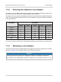
1.7.4 Selecting the Optimum Lens Adapter . . . . . . . . . . . . . . . . . . . . . . . . . . . . . . 17
1.7.5 Attaching a Lens Adapter. . . . . . . . . . . . . . . . . . . . . . . . . . . . . . . . . . . . . . . . 17
1.8 Mechanical Stress Test Results . . . . . . . . . . . . . . . . . . . . . . . . . . . . . . . . . . . . . . . . . . 18
1.9 Software Licensing Information . . . . . . . . . . . . . . . . . . . . . . . . . . . . . . . . . . . . . . . . . . 19
1.9.1 LWIP TCP/IP Licensing . . . . . . . . . . . . . . . . . . . . . . . . . . . . . . . . . . . . . . . . . 19
1.9.2 LZ4 Licensing. . . . . . . . . . . . . . . . . . . . . . . . . . . . . . . . . . . . . . . . . . . . . . . . . 20
1.10 Avoiding EMI and ESD Problems . . . . . . . . . . . . . . . . . . . . . . . . . . . . . . . . . . . . . . . . . 21
1.11 Environmental Requirements . . . . . . . . . . . . . . . . . . . . . . . . . . . . . . . . . . . . . . . . . . . . 22
1.11.1 Temperature and Humidity. . . . . . . . . . . . . . . . . . . . . . . . . . . . . . . . . . . . . . . 22
1.11.2 Heat Dissipation . . . . . . . . . . . . . . . . . . . . . . . . . . . . . . . . . . . . . . . . . . . . . . . 22
1.11.3 Imaging Sensor Over Temperature Condition . . . . . . . . . . . . . . . . . . . . . . . . 23
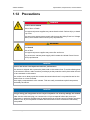
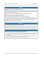
1.12 Precautions. . . . . . . . . . . . . . . . . . . . . . . . . . . . . . . . . . . . . . . . . . . . . . . . . . . . . . . . . . 24
2 Software and Hardware Installation . . . . . . . . . . . . . . . . . . . . . . . . . . . . . . . . . 27
3 Tools for Changing Camera Parameters . . . . . . . . . . . . . . . . . . . . . . . . . . . . . 28
3.1 Basler pylon Camera Software Suite . . . . . . . . . . . . . . . . . . . . . . . . . . . . . . . . . . . . . . 28
3.1.1 pylon Viewer. . . . . . . . . . . . . . . . . . . . . . . . . . . . . . . . . . . . . . . . . . . . . . . . . . 28
3.1.2 pylon IP Configurator . . . . . . . . . . . . . . . . . . . . . . . . . . . . . . . . . . . . . . . . . . . 29
3.1.3 pylon SDKs . . . . . . . . . . . . . . . . . . . . . . . . . . . . . . . . . . . . . . . . . . . . . . . . . . 29
4 Basler Network Drivers and Parameters . . . . . . . . . . . . . . . . . . . . . . . . . . . . . 30
4.1 The Basler Filter Driver. . . . . . . . . . . . . . . . . . . . . . . . . . . . . . . . . . . . . . . . . . . . . . . . . 31
4.2 The Basler Performance Driver . . . . . . . . . . . . . . . . . . . . . . . . . . . . . . . . . . . . . . . . . . 32
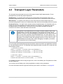
4.3 Transport Layer Parameters. . . . . . . . . . . . . . . . . . . . . . . . . . . . . . . . . . . . . . . . . . . . . 40
5 Network Related Camera Parameters and Managing Bandwidth . . . . . . . . . 41
5.1 Network Related Parameters in the Camera . . . . . . . . . . . . . . . . . . . . . . . . . . . . . . . . 41
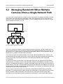
5.2 Managing Bandwidth When Multiple Cameras Share a Single Network Path . . . . . . . 43
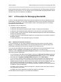
5.2.1 A Procedure for Managing Bandwidth . . . . . . . . . . . . . . . . . . . . . . . . . . . . . . 44

Table of Contents AW00118308000
ii Basler racer GigE
6 Camera Functional Description . . . . . . . . . . . . . . . . . . . . . . . . . . . . . . . . . . . . .49
7 Physical Interface . . . . . . . . . . . . . . . . . . . . . . . . . . . . . . . . . . . . . . . . . . . . . . . .52
7.1 Connectors and Pin Numbering . . . . . . . . . . . . . . . . . . . . . . . . . . . . . . . . . . . . . . . . . . 52
7.2 Connector Pin Assignments . . . . . . . . . . . . . . . . . . . . . . . . . . . . . . . . . . . . . . . . . . . . . 54
7.2.1 Pin Assignments for the 6-pin Connector . . . . . . . . . . . . . . . . . . . . . . . . . . . 54
7.2.2 Pin Assignments for the 12-pin Connector . . . . . . . . . . . . . . . . . . . . . . . . . . 55
7.2.3 Pin Assignments for the RJ-45 Jack . . . . . . . . . . . . . . . . . . . . . . . . . . . . . . . 55
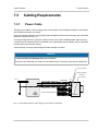
7.3 Cabling Requirements . . . . . . . . . . . . . . . . . . . . . . . . . . . . . . . . . . . . . . . . . . . . . . . . . 56
7.3.1 Power Cable . . . . . . . . . . . . . . . . . . . . . . . . . . . . . . . . . . . . . . . . . . . . . . . . . 56
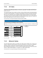
7.3.2 I/O Cable . . . . . . . . . . . . . . . . . . . . . . . . . . . . . . . . . . . . . . . . . . . . . . . . . . . . 57
7.3.3 Ethernet Cables . . . . . . . . . . . . . . . . . . . . . . . . . . . . . . . . . . . . . . . . . . . . . . . 57
7.4 Camera Power . . . . . . . . . . . . . . . . . . . . . . . . . . . . . . . . . . . . . . . . . . . . . . . . . . . . . . . 58
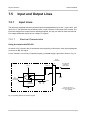
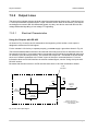
7.5 Input and Output Lines . . . . . . . . . . . . . . . . . . . . . . . . . . . . . . . . . . . . . . . . . . . . . . . . . 59
7.5.1 Input Lines . . . . . . . . . . . . . . . . . . . . . . . . . . . . . . . . . . . . . . . . . . . . . . . . . . . 59
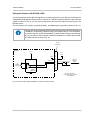
7.5.1.1 Electrical Characteristics . . . . . . . . . . . . . . . . . . . . . . . . . . . . . . . 59
7.5.1.2 Input Line Debouncers . . . . . . . . . . . . . . . . . . . . . . . . . . . . . . . . 63
7.5.1.3 Input Line Inverters . . . . . . . . . . . . . . . . . . . . . . . . . . . . . . . . . . . 63
7.5.1.4 Selecting an Input Line as a Source Signal for a
Camera Function. . . . . . . . . . . . . . . . . . . . . . . . . . . . . . . . . . . . . 64
7.5.2 Output Lines. . . . . . . . . . . . . . . . . . . . . . . . . . . . . . . . . . . . . . . . . . . . . . . . . . 65
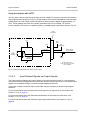
7.5.2.1 Electrical Characteristics . . . . . . . . . . . . . . . . . . . . . . . . . . . . . . . 65
7.5.2.2 Input Related Signals as Output Signals . . . . . . . . . . . . . . . . . . . 67
7.5.2.3 Minimum Output Pulse Width . . . . . . . . . . . . . . . . . . . . . . . . . . . 68
7.5.2.4 Output Line Inverters. . . . . . . . . . . . . . . . . . . . . . . . . . . . . . . . . . 68
7.5.2.5 Selecting the Source Signal for an Output Line. . . . . . . . . . . . . . 69
7.5.2.6 Setting the State of User Settable Output Lines . . . . . . . . . . . . . 71
7.5.3 Checking the State of the I/O Lines . . . . . . . . . . . . . . . . . . . . . . . . . . . . . . . . 72
7.5.4 Checking the Line Logic. . . . . . . . . . . . . . . . . . . . . . . . . . . . . . . . . . . . . . . . . 73
7.5.5 I/O Line Response Times . . . . . . . . . . . . . . . . . . . . . . . . . . . . . . . . . . . . . . . 74
7.6 Ethernet GigE Device Information . . . . . . . . . . . . . . . . . . . . . . . . . . . . . . . . . . . . . . . . 74
8 Acquisition Control . . . . . . . . . . . . . . . . . . . . . . . . . . . . . . . . . . . . . . . . . . . . . . .75
8.1 Defining a Frame . . . . . . . . . . . . . . . . . . . . . . . . . . . . . . . . . . . . . . . . . . . . . . . . . . . . . 75
8.2 Controlling Acquisition . . . . . . . . . . . . . . . . . . . . . . . . . . . . . . . . . . . . . . . . . . . . . . . . . 78
8.2.1 Acquisition Start and Stop Commands and the Acquisition Mode. . . . . . . . . 78
8.2.2 Acquisition Start Triggering . . . . . . . . . . . . . . . . . . . . . . . . . . . . . . . . . . . . . . 80
8.2.2.1 TriggerMode (Acquisition Start) = Off . . . . . . . . . . . . . . . . . . . . . 80
8.2.2.2 TriggerMode (Acquisition Start) = On . . . . . . . . . . . . . . . . . . . . . 80
8.2.2.3 AcquisitionFrameCount . . . . . . . . . . . . . . . . . . . . . . . . . . . . . . . . 81
8.2.2.4 Setting The Acquisition Start Trigger Mode and
Related Parameters. . . . . . . . . . . . . . . . . . . . . . . . . . . . . . . . . . . 82
8.2.3 Frame Start Triggering. . . . . . . . . . . . . . . . . . . . . . . . . . . . . . . . . . . . . . . . . . 83
8.2.3.1 TriggerMode (Frame Start) = Off. . . . . . . . . . . . . . . . . . . . . . . . . 83
8.2.3.2 TriggerMode (Frame Start) = On. . . . . . . . . . . . . . . . . . . . . . . . . 83

AW00118308000 Table of Contents
Basler racer GigE iii
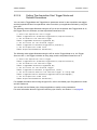
8.2.3.3 Setting the Frame Start Trigger Parameters . . . . . . . . . . . . . . . . 85
8.2.3.4 Frame Timeout . . . . . . . . . . . . . . . . . . . . . . . . . . . . . . . . . . . . . . 86
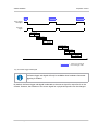
8.2.4 Line Start Triggering. . . . . . . . . . . . . . . . . . . . . . . . . . . . . . . . . . . . . . . . . . . . 87
8.2.4.1 TriggerMode (Line Start) = Off. . . . . . . . . . . . . . . . . . . . . . . . . . . 87
8.2.4.2 TriggerMode (Line Start) = On. . . . . . . . . . . . . . . . . . . . . . . . . . . 88
8.2.4.3 Setting the Line Start Trigger Parameters . . . . . . . . . . . . . . . . . . 91
8.2.5 Exposure Time . . . . . . . . . . . . . . . . . . . . . . . . . . . . . . . . . . . . . . . . . . . . . . . . 92
8.2.5.1 Minimum and Maximum Exposure Times . . . . . . . . . . . . . . . . . . 92
8.2.5.2 Exposure Time Parameters . . . . . . . . . . . . . . . . . . . . . . . . . . . . . 93
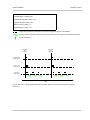
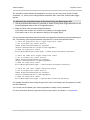
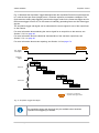
8.2.6 Use Case Descriptions and Diagrams . . . . . . . . . . . . . . . . . . . . . . . . . . . . . . 95
8.2.7 Overlapping Exposure with Sensor Readout . . . . . . . . . . . . . . . . . . . . . . . . 113
8.2.7.1 Guidelines for Overlapped Operation . . . . . . . . . . . . . . . . . . . . 114
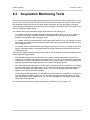
8.3 Acquisition Monitoring Tools. . . . . . . . . . . . . . . . . . . . . . . . . . . . . . . . . . . . . . . . . . . . 120
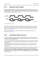
8.3.1 Exposure Active Signal . . . . . . . . . . . . . . . . . . . . . . . . . . . . . . . . . . . . . . . . 121
8.3.2 Acquisition Status Indicator . . . . . . . . . . . . . . . . . . . . . . . . . . . . . . . . . . . . . 121
8.3.3 Trigger Wait Signals. . . . . . . . . . . . . . . . . . . . . . . . . . . . . . . . . . . . . . . . . . . 123
8.3.3.1 Acquisition Trigger Wait Signal . . . . . . . . . . . . . . . . . . . . . . . . . 123
8.3.3.2 Frame Trigger Wait Signal. . . . . . . . . . . . . . . . . . . . . . . . . . . . . 125
8.3.3.3 Line Trigger Wait Signal . . . . . . . . . . . . . . . . . . . . . . . . . . . . . . 127
8.4 Frame Transmission Time . . . . . . . . . . . . . . . . . . . . . . . . . . . . . . . . . . . . . . . . . . . . . 131
8.5 Maximum Allowed Line Acquisition Rate . . . . . . . . . . . . . . . . . . . . . . . . . . . . . . . . . . 132
8.5.1 Removing the Parameter Limits for the ExposureOverhead Parameter . . . 135
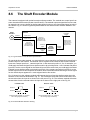
8.6 The Shaft Encoder Module . . . . . . . . . . . . . . . . . . . . . . . . . . . . . . . . . . . . . . . . . . . . . 137
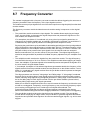
8.7 Frequency Converter . . . . . . . . . . . . . . . . . . . . . . . . . . . . . . . . . . . . . . . . . . . . . . . . . 146
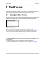
9 Pixel Formats . . . . . . . . . . . . . . . . . . . . . . . . . . . . . . . . . . . . . . . . . . . . . . . . . . 148
9.1 Setting the Pixel Format . . . . . . . . . . . . . . . . . . . . . . . . . . . . . . . . . . . . . . . . . . . . . . . 148
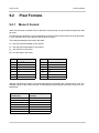
9.2 Pixel Formats . . . . . . . . . . . . . . . . . . . . . . . . . . . . . . . . . . . . . . . . . . . . . . . . . . . . . . . 149
9.2.1 Mono 8 Format. . . . . . . . . . . . . . . . . . . . . . . . . . . . . . . . . . . . . . . . . . . . . . . 149
9.2.2 Mono 12 Format . . . . . . . . . . . . . . . . . . . . . . . . . . . . . . . . . . . . . . . . . . . . . . 150
9.2.3 Mono 12 Packed Format . . . . . . . . . . . . . . . . . . . . . . . . . . . . . . . . . . . . . . . 151
9.2.4 YUV 4:2:2 Packed Format . . . . . . . . . . . . . . . . . . . . . . . . . . . . . . . . . . . . . . 153
9.2.5 YUV 4:2:2 (YUYV Packed) Format . . . . . . . . . . . . . . . . . . . . . . . . . . . . . . . 154
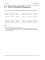
9.3 Pixel Transmission Sequence . . . . . . . . . . . . . . . . . . . . . . . . . . . . . . . . . . . . . . . . . . 157
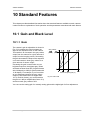
10 Standard Features . . . . . . . . . . . . . . . . . . . . . . . . . . . . . . . . . . . . . . . . . . . . . . 158
10.1 Gain and Black Level . . . . . . . . . . . . . . . . . . . . . . . . . . . . . . . . . . . . . . . . . . . . . . . . . 158
10.1.1 Gain . . . . . . . . . . . . . . . . . . . . . . . . . . . . . . . . . . . . . . . . . . . . . . . . . . . . . . . 158
10.1.1.1 Analog Gain . . . . . . . . . . . . . . . . . . . . . . . . . . . . . . . . . . . . . . . 159
10.1.1.2 Digital Gain . . . . . . . . . . . . . . . . . . . . . . . . . . . . . . . . . . . . . . . . 159
10.1.1.3 Using Both Analog Gain and Digital Gain . . . . . . . . . . . . . . . . . 161
10.1.2 Black Level. . . . . . . . . . . . . . . . . . . . . . . . . . . . . . . . . . . . . . . . . . . . . . . . . . 161
10.2 Remove Parameter Limits . . . . . . . . . . . . . . . . . . . . . . . . . . . . . . . . . . . . . . . . . . . . . 162
10.3 Image Area of Interest . . . . . . . . . . . . . . . . . . . . . . . . . . . . . . . . . . . . . . . . . . . . . . . . 163

Table of Contents AW00118308000
iv Basler racer GigE
10.3.1 Setting the Image AOI . . . . . . . . . . . . . . . . . . . . . . . . . . . . . . . . . . . . . . . . . 163
10.3.2 Automatic Image AOI X Centering. . . . . . . . . . . . . . . . . . . . . . . . . . . . . . . . 164
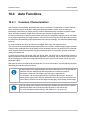
10.4 Auto Functions . . . . . . . . . . . . . . . . . . . . . . . . . . . . . . . . . . . . . . . . . . . . . . . . . . . . . . 165
10.4.1 Common Characteristics . . . . . . . . . . . . . . . . . . . . . . . . . . . . . . . . . . . . . . . 165
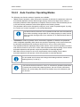
10.4.2 Auto Function Operating Modes . . . . . . . . . . . . . . . . . . . . . . . . . . . . . . . . . 166
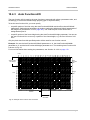
10.4.3 Auto Function AOI . . . . . . . . . . . . . . . . . . . . . . . . . . . . . . . . . . . . . . . . . . . . 167
10.4.3.1 Positioning of the Auto Function AOI Relative to the Image
AOI . . . . . . . . . . . . . . . . . . . . . . . . . . . . . . . . . . . . . . . . . . . . . . 168
10.4.3.2 Setting the Auto Function AOI. . . . . . . . . . . . . . . . . . . . . . . . . . 170
10.4.4 Gain Auto . . . . . . . . . . . . . . . . . . . . . . . . . . . . . . . . . . . . . . . . . . . . . . . . . . . 171
10.4.5 Exposure Auto . . . . . . . . . . . . . . . . . . . . . . . . . . . . . . . . . . . . . . . . . . . . . . . 172
10.4.6 Gray Value Adjustment Damping . . . . . . . . . . . . . . . . . . . . . . . . . . . . . . . . 174
10.4.7 Auto Function Profile . . . . . . . . . . . . . . . . . . . . . . . . . . . . . . . . . . . . . . . . . . 175
10.5 Event Reporting . . . . . . . . . . . . . . . . . . . . . . . . . . . . . . . . . . . . . . . . . . . . . . . . . . . . . 176
10.6 Luminance Lookup Table . . . . . . . . . . . . . . . . . . . . . . . . . . . . . . . . . . . . . . . . . . . . . . 179
10.7 Binning . . . . . . . . . . . . . . . . . . . . . . . . . . . . . . . . . . . . . . . . . . . . . . . . . . . . . . . . . . . . 182
10.8 Gamma Correction . . . . . . . . . . . . . . . . . . . . . . . . . . . . . . . . . . . . . . . . . . . . . . . . . . . 183
10.9 Shading Correction. . . . . . . . . . . . . . . . . . . . . . . . . . . . . . . . . . . . . . . . . . . . . . . . . . . 184
10.9.1 Offset Shading Correction . . . . . . . . . . . . . . . . . . . . . . . . . . . . . . . . . . . . . . 184
10.9.2 Gain Shading Correction . . . . . . . . . . . . . . . . . . . . . . . . . . . . . . . . . . . . . . . 184
10.9.3 Default Shading Set File and User Shading Set File . . . . . . . . . . . . . . . . . 185
10.9.3.1 Creating "Usershading" Files. . . . . . . . . . . . . . . . . . . . . . . . . . . 185
10.9.3.2 Working with Shading Sets . . . . . . . . . . . . . . . . . . . . . . . . . . . . 189
10.10 Trigger Delay . . . . . . . . . . . . . . . . . . . . . . . . . . . . . . . . . . . . . . . . . . . . . . . . . . . . . . . 191
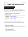
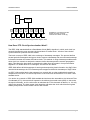
10.11 Precision Time Protocol (IEEE 1588) . . . . . . . . . . . . . . . . . . . . . . . . . . . . . . . . . . . . . 192
10.11.1 Enabling PTP Clock Synchronization . . . . . . . . . . . . . . . . . . . . . . . . . . . . . 195
10.11.2 Checking the Status of the PTP Clock Synchronization . . . . . . . . . . . . . . . 196
10.12 Action Commands . . . . . . . . . . . . . . . . . . . . . . . . . . . . . . . . . . . . . . . . . . . . . . . . . . . 198
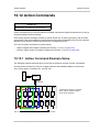
10.12.1 Action Command Example Setup . . . . . . . . . . . . . . . . . . . . . . . . . . . . . . . . 198
10.12.2 Action Command Parameters . . . . . . . . . . . . . . . . . . . . . . . . . . . . . . . . . . . 199
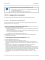
10.12.3 Using Action Commands . . . . . . . . . . . . . . . . . . . . . . . . . . . . . . . . . . . . . . . 201
10.12.3.1 Synchronous Image Acquisition . . . . . . . . . . . . . . . . . . . . . . . . 201
10.12.3.2 Synchronous Frame Counter Reset . . . . . . . . . . . . . . . . . . . . . 203
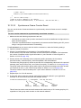
10.13 Scheduled Action Commands . . . . . . . . . . . . . . . . . . . . . . . . . . . . . . . . . . . . . . . . . . 205
10.13.1 Scheduled Action Command Parameters . . . . . . . . . . . . . . . . . . . . . . . . . . 205
10.13.2 Using Scheduled Action Commands . . . . . . . . . . . . . . . . . . . . . . . . . . . . . . 206
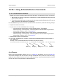
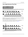
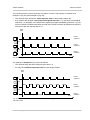
10.14 Synchronous Free Run. . . . . . . . . . . . . . . . . . . . . . . . . . . . . . . . . . . . . . . . . . . . . . . . 207
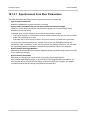
10.14.1 Synchronous Free Run Parameters . . . . . . . . . . . . . . . . . . . . . . . . . . . . . . 209
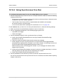
10.14.2 Using Synchronous Free Run . . . . . . . . . . . . . . . . . . . . . . . . . . . . . . . . . . . 210
10.15 Error Codes . . . . . . . . . . . . . . . . . . . . . . . . . . . . . . . . . . . . . . . . . . . . . . . . . . . . . . . . 212
10.16 Test Images . . . . . . . . . . . . . . . . . . . . . . . . .
.
. . . . . . . . . . . . . . . . . . . . . . . . . . . . . . 214
10.17 Device Information Parameters . . . . . . . . . . . . . . . . . . . . . . . . . . . . . . . . . . . . . . . . . 217
10.18 User Defined Values. . . . . . . . . . . . . . . . . . . . . . . . . . . . . . . . . . . . . . . . . . . . . . . . . . 219

AW00118308000 Table of Contents
Basler racer GigE v
10.19 Configuration Sets . . . . . . . . . . . . . . . . . . . . . . . . . . . . . . . . . . . . . . . . . . . . . . . . . . . 220
10.19.1 Saving Configuration Sets . . . . . . . . . . . . . . . . . . . . . . . . . . . . . . . . . . . . . . 221
10.19.2 Loading a Saved Set or the Default Set into the Active Set. . . . . . . . . . . . . 222
10.19.3 Selecting the Default Startup Set . . . . . . . . . . . . . . . . . . . . . . . . . . . . . . . . . 222
11 Chunk Features. . . . . . . . . . . . . . . . . . . . . . . . . . . . . . . . . . . . . . . . . . . . . . . . . 223
11.1 What are Chunk Features?. . . . . . . . . . . . . . . . . . . . . . . . . . . . . . . . . . . . . . . . . . . . . 223
11.2 Making the "Chunk Mode" Active and Enabling the Extended Data Stamp . . . . . . . . 224
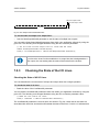
11.3 Frame Counter . . . . . . . . . . . . . . . . . . . . . . . . . . . . . . . . . . . . . . . . . . . . . . . . . . . . . . 226
11.4 Time Stamp . . . . . . . . . . . . . . . . . . . . . . . . . . . . . . . . . . . . . . . . . . . . . . . . . . . . . . . . 228
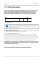
11.5 Trigger Counters. . . . . . . . . . . . . . . . . . . . . . . . . . . . . . . . . . . . . . . . . . . . . . . . . . . . . 229
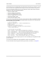
11.5.1 Enabling the Trigger Counters and Retrieving Chunk Data . . . . . . . . . . . . . 231
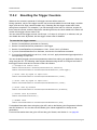
11.5.2 Resetting the Trigger Counters . . . . . . . . . . . . . . . . . . . . . . . . . . . . . . . . . . 233
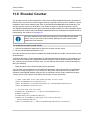
11.6 Encoder Counter. . . . . . . . . . . . . . . . . . . . . . . . . . . . . . . . . . . . . . . . . . . . . . . . . . . . . 234
11.7 Input Line Status At Line Trigger . . . . . . . . . . . . . . . . . . . . . . . . . . . . . . . . . . . . . . . . 235
11.8 CRC Checksum . . . . . . . . . . . . . . . . . . . . . . . . . . . . . . . . . . . . . . . . . . . . . . . . . . . . . 237
12 Troubleshooting and Support . . . . . . . . . . . . . . . . . . . . . . . . . . . . . . . . . . . . . 239
12.1 Camera Reset. . . . . . . . . . . . . . . . . . . . . . . . . . . . . . . . . . . . . . . . . . . . . . . . . . . . . . . 239
12.2 Tech Support Resources . . . . . . . . . . . . . . . . . . . . . . . . . . . . . . . . . . . . . . . . . . . . . . 240
12.3 Obtaining an RMA Number. . . . . . . . . . . . . . . . . . . . . . . . . . . . . . . . . . . . . . . . . . . . . 240
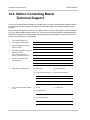
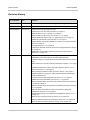
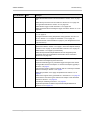
12.4 Before Contacting Basler Technical Support . . . . . . . . . . . . . . . . . . . . . . . . . . . . . . . 241
Revision History. . . . . . . . . . . . . . . . . . . . . . . . . . . . . . . . . . . . . . . . . . . . . . . . . . . . . . . . . . 243
Index. . . . . . . . . . . . . . . . . . . . . . . . . . . . . . . . . . . . . . . . . . . . . . . . . . . . . . . . . . . . . . . . . . . . . 246

Specifications, Requirements, and Precautions AW00118308000
1 Basler racer GigE
1 Specifications, Requirements,
and Precautions
This chapter lists the camera models covered by the manual. It provides the general specifications
for those models and the basic requirements for using them.
This chapter also includes specific precautions that you should keep in mind when using the
cameras. Basler strongly recommends that you read and follow the precautions.
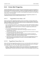
1.1 Intended Use
Basler digital cameras for machine vision are designed exclusively for indoor professional image
capture. Temperature and humidity requirements apply as detailed in Section 1.11 on page 22. All
relevant product documentation must be observed, including directions for correct camera use.
The cameras must not be used for the following:
Purposes and installations requiring special camera certification other than mentioned in this
documentation.
Purposes and installations requiring specific design and precautions for use under harsh
conditions.
If in doubt whether a specific camera is compatible with certain operating conditions and uses,
contact your sales representative.
1.2 Authorized Users
Basler digital cameras for machine vision are designed for use by professionals only, concerned
with the following tasks:
Selection of cameras for use
Camera integration and setup
Everyday camera use
This documentation assumes the skills of electrical engineers, systems engineers, mechatronics
engineers, technicians, and information technology engineers.

AW00118308000 Specifications, Requirements, and Precautions
Basler racer GigE 2
Camera use is not allowed for persons with insufficient skills or with impairments that prevent them
from doing the following tasks:
Using cameras correctly
Adhering to the safety instructions
Fully understanding all relevant camera documentation
1.3 Models
The current Basler racer GigE Vision camera models are listed in the top row of the specification
tables on the next pages of this manual. The camera models are differentiated by their resolution
and their maximum line rate at full resolution.
Unless otherwise noted, the material in this manual applies to all of the camera models listed in the
tables. Material that only applies to a particular camera model or to a subset of models will be so
designated.

Specifications, Requirements, and Precautions AW00118308000
3 Basler racer GigE
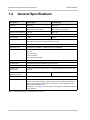
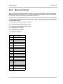
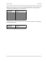
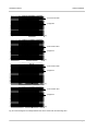
1.4 General Specifications
Specification raL2048-48gm raL4096-24gm
Resolution 2048 pixels 4096 pixels
Sensor Type Awaiba DR-2k-7
Monochrome Linear CMOS
Awaiba DR-4k-7
Monochrome Linear CMOS
Effective Sensor Diagonal 14.34 mm 28.67 mm
Pixel Size 7 µm x 7 µm
Max Line Rate 51 kHz 26 kHz
Min Line Rate No minimum when an external line trigger signal is used
100 Hz when an external line trigger signal is not used
Mono/Color Mono
Data Output Type Fast Ethernet (100 Mbit/s) or Gigabit Ethernet (1000 Mbit/s)
Pixel Formats Mono 8
Mono 12
Mono 12 Packed
YUV 4:2:2 Packed
YUV 4:2:2 (YUYV) Packed
ADC Bit Depth 12 bit
Synchronization Via hardware trigger, via software trigger, or free run
Exposure Time Control Programmable via the camera API
Camera Power
Requirements
+12 VDC (-10 %) to +24 VDC (+5 %), < 1 % ripple, supplied via the camera’s 6-pin
connector
Power Consumption
(typical, at 12 VDC)
3W 4W
I/O Lines 3 input lines and 2 output lines
Lens Adapter Universal camera front, suitable for lens mount adapters with the following lens
mounts: C-mount (2k cameras), F-mount, M42x0.75-mount (back flange distance
(FBD) 16 mm), M42x1.0-mount (FBD 16 mm), M42x1.0-mount (FBD 45.56 mm),
M58x0.75-mount (FBD 20 mm).
See Section 1.7.4 on page 17 for information about selecting a suitable lens adapter
for your camera.
Table 1: General Specifications - 2k and 4k Mono Cameras

AW00118308000 Specifications, Requirements, and Precautions
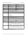
Basler racer GigE 4
Size
(L x W x H)
36.12 mm x 56 mm x 62 mm (without lens adapter or connectors)
50.83 mm x 56 mm x 62 mm (with C-mount lens adapter and connectors)
79.92 mm x 56 mm x 62 mm (with F-mount lens adapter and connectors)
49.42 mm x 56 mm x 62 mm (with M42-mount lens adapter and connectors)
78.98 mm x 56 mm x 62 mm (with M42-mount FBD 45.56 mm lens adapter and
connectors)
53.42 mm x 56 mm x 62 mm (with M58-mount lens adapter and connectors)
Weight ≈ 240 g (typical) without lens adapter
≈ 270 g (typical) with C-mount lens adapter and connectors
≈ 330 g (typical) with F-mount lens adapter and connectors
≈ 260 g (typical) with M42-mount lens adapter and connectors
≈ 310 g (typical) with M42-mount FBD 45.56 lens adapter and connectors
≈ 270 g (typical) with M58-mount lens adapter and connectors
Conformity CE (includes RoHS), FCC, UL Listed, GenICam, GigE Vision, IP30, REACH
The CE Conformity Declaration is available on the Basler website:
www.baslerweb.com
Software Basler pylon Camera Software Suite (version 4.0 or higher)
Available for Windows, Linux x86, Linux ARM, and OS X
Specification raL2048-48gm raL4096-24gm
Table 1: General Specifications - 2k and 4k Mono Cameras

Specifications, Requirements, and Precautions AW00118308000
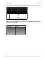
5 Basler racer GigE
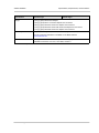
Specification raL6144-16gm raL8192-12gm
Resolution 6144 pixels 8192 pixels
Sensor Type Awaiba DR-6k-7
Monochrome Linear CMOS
Awaiba DR-8k-3.5
Monochrome Linear CMOS
Effective Sensor Diagonal 43.01 mm 28.67 mm
Pixel Size 7 µm x 7 µm 3.5 µm x 3.5 µm
Max Line Rate 17 kHz 12 kHz
Min Line Rate No minimum when an external line trigger signal is used
100 Hz when an external line trigger signal is not used
Mono/Color Mono
Data Output Type Fast Ethernet (100 Mbit/s) or Gigabit Ethernet (1000 Mbit/s)
Pixel Formats Mono 8
Mono 12
Mono 12 Packed
YUV 4:2:2 Packed
YUV 4:2:2 (YUYV) Packed
ADC Bit Depth 12 bit
Synchronization Via hardware trigger, via software trigger, or free run
Exposure Time Control Programmable via the camera API
Camera Power
Requirements
+12 VDC (-10 %) to +24 VDC (+5 %), < 1 % ripple, supplied via the camera’s 6-pin
connector
Power Consumption
(typical, at 12 VDC)
4.5 W 5.5 W
I/O Lines 3 input lines and 2 output lines
Lens Adapter Universal camera front, suitable for lens mount adapters with the following lens
mounts: F-mount, M42x0.75-mount (FBD 16 mm), M42x1.0-mount (FBD 16 mm),
M42x1.0-mount (FBD 45.56 mm), M58x0.75-mount (FBD 20 mm).
See Section 1.7.4 on page 17 for information about selecting a suitable lens adapter
for your camera.
Size
(L x W x H)
36.12 mm x 56 mm x 62 mm (without lens adapter or connectors)
79.92 mm x 56 mm x 62 mm (with F-mount lens adapter and connectors)
49.42 mm x 56 mm x 62 mm (with M42-mount lens adapter and connectors)
78.98 mm x 56 mm x 62 mm (with M42-mount FBD 45.56 mm lens adapter and
connectors)
53.42 mm x 56 mm x 62 mm (with M58-mount lens adapter and connectors)
Table 2: General Specifications - 6k and 8k Mono Cameras

AW00118308000 Specifications, Requirements, and Precautions
Basler racer GigE 6
Weight ≈ 240 g (typical) without lens adapter
≈ 330 g (typical) with F-mount lens adapter and connectors
≈ 260 g (typical) with M42-mount lens adapter and connectors
≈ 310 g (typical) with M42-mount FBD 45.56 lens adapter and connectors
≈ 270 g (typical) with M58-mount lens adapter and connectors
Conformity CE (includes RoHS), FCC, UL Listed, GenICam, GigE Vision, IP30, REACH
The CE Conformity Declaration is available on the Basler website:
www.baslerweb.com
Software Basler pylon Camera Software Suite (version 4.0 or higher)
Available for Windows, Linux x86, Linux ARM, and OS X
Specification raL6144-16gm raL8192-12gm
Table 2: General Specifications - 6k and 8k Mono Cameras

Specifications, Requirements, and Precautions AW00118308000
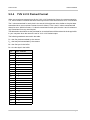
7 Basler racer GigE
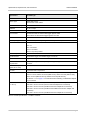
Specification raL12288-8gm
Resolution 12288 pixels
Sensor Type Awaiba DR-12k-3.5
Monochrome Linear CMOS
Effective Sensor Diagonal 43.01 mm
Pixel Size 3.5 µm x 3.5 µm
Max Line Rate 8 kHz
Min Line Rate No minimum when an external line trigger signal is used
100 Hz when an external line trigger signal is not used
Mono/Color Mono
Data Output Type Fast Ethernet (100 Mbit/s) or Gigabit Ethernet (1000 Mbit/s)
Pixel Formats Mono 8
Mono 12
Mono 12 Packed
YUV 4:2:2 Packed
YUV 4:2:2 (YUYV) Packed
ADC Bit Depth 12 bit
Synchronization Via hardware trigger, via software trigger, or free run
Exposure Time Control Programmable via the camera API
Camera Power
Requirements
+12 VDC (-10 %) to +24 VDC (+5 %), < 1 % ripple, supplied via the camera’s 6-pin
connector
Power Consumption
(typical, at 12 VDC)
6.5 W
I/O Lines 3 input lines and 2 output lines
Lens Adapter Universal camera front, suitable for lens mount adapters with the following lens
mounts: F-mount, M42x0.75-mount (FBD 16 mm), M42x1.0-mount (FBD 16 mm),
M42x1.0-mount (FBD 45.56 mm), M58x0.75-mount (FBD 20 mm).
See Section 1.7.4 on page 17 for information about selecting a suitable lens adapter
for your camera.
Size
(L x W x H)
36.12 mm x 56 mm x 62 mm (without lens adapter or connectors)
79.92 mm x 56 mm x 62 mm (with F-mount lens adapter and connectors)
49.42 mm x 56 mm x 62 mm (with M42-mount lens adapter and connectors)
78.98 mm x 56 mm x 62 mm (with M42-mount FBD 45.56 mm lens adapter and
connectors)
53.42 mm x 56 mm x 62 mm (with M58-mount lens adapter and connectors)
Table 3: General Specifications - 12k Mono Cameras

AW00118308000 Specifications, Requirements, and Precautions
Basler racer GigE 8
Weight ≈ 240 g (typical) without lens adapter
≈ 330 g (typical) with F-mount lens adapter and connectors
≈ 260 g (typical) with M42-mount lens adapter and connectors
≈ 310 g (typical) with M42-mount FBD 45.56 lens adapter and connectors
≈ 270 g (typical) with M58-mount lens adapter and connectors
Conformity CE (includes RoHS), FCC, UL Listed, GenICam, GigE Vision, IP30, REACH
The CE Conformity Declaration is available on the Basler website:
www.baslerweb.com
Software Basler pylon Camera Software Suite (version 4.0 or higher)
Available for Windows, Linux x86, Linux ARM, and OS X
Specification raL12288-8gm
Table 3: General Specifications - 12k Mono Cameras

Specifications, Requirements, and Precautions AW00118308000
9 Basler racer GigE
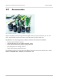
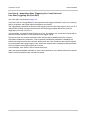
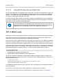
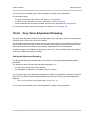
1.5 Accessories
Basler’s cooperation with carefully selected suppliers means you get accessories you can trust
which makes building a high-performance image processing system hassle-free.
Key Reasons for Choosing Lenses, Cables, and Other Accessories from Basler
Perfect match for Basler cameras
One-stop-shopping for your image processing system
Stable performance through highest quality standards
Easy integration into existing systems
Expert advice during selection process
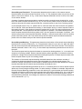
See the Basler website for information about Basler’s extensive accessories portfolio (e.g. cables,
lenses, host adapter cards, switches): www.baslerweb.com
Fig. 1: Basler Accessories

AW00118308000 Specifications, Requirements, and Precautions
Basler racer GigE 10
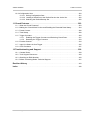
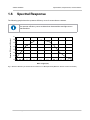
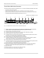
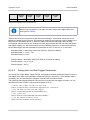
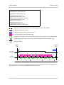
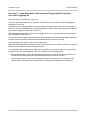
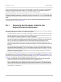
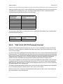
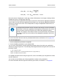
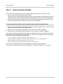
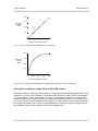
1.6 Spectral Response
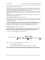
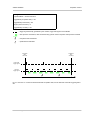
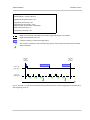
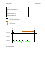
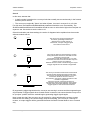
The following graph shows the quantum efficiency curve for monochrome cameras.
Fig. 2: Quantum Efficiency of the Monochrome Sensor in 12 Bit Depth Mode (Based on Sensor Vendor Information)
The quantum efficiency curve excludes lens characteristics and light source
characteristics.
300 400 500 600 700 800 900 1000 1100
0.0
0.1
0.2
0.3
0.4
0.5
0.6
0.7
Wave Length (nm)
Quantum Efficiency (e
-
/Photon)

Specifications, Requirements, and Precautions AW00118308000
11 Basler racer GigE
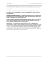
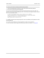
1.7 Mechanical Specifications
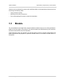
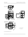
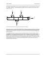
1.7.1 Camera Dimensions and Mounting Points
The cameras are manufactured with high precision. Planar, parallel, and angular sides ensures
precise mounting with high repeatability.
The camera housings conform to the IP30 protection class provided the camera front is covered by
the protective plastic seal that is shipped with the camera.
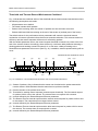
The camera’s dimensions in millimeters are as shown in the drawings below.
Camera housings are equipped with four mounting holes (4 x M4; 6.3 deep) on the front and two
mounting holes (8 x M4; 6.3 deep) on each side as shown in the drawings. Four additional holes
(4 x M2.5; 3.3 deep) are present on the camera front for mounting the lens mount adapter.
Page is loading ...
Page is loading ...
Page is loading ...
Page is loading ...
Page is loading ...
Page is loading ...
Page is loading ...
Page is loading ...
Page is loading ...
Page is loading ...
Page is loading ...
Page is loading ...
Page is loading ...
Page is loading ...
Page is loading ...
Page is loading ...
Page is loading ...
Page is loading ...
Page is loading ...
Page is loading ...
Page is loading ...
Page is loading ...
Page is loading ...
Page is loading ...
Page is loading ...
Page is loading ...
Page is loading ...
Page is loading ...
Page is loading ...
Page is loading ...
Page is loading ...
Page is loading ...
Page is loading ...
Page is loading ...
Page is loading ...
Page is loading ...
Page is loading ...
Page is loading ...
Page is loading ...
Page is loading ...
Page is loading ...
Page is loading ...
Page is loading ...
Page is loading ...
Page is loading ...
Page is loading ...
Page is loading ...
Page is loading ...
Page is loading ...
Page is loading ...
Page is loading ...
Page is loading ...
Page is loading ...
Page is loading ...
Page is loading ...
Page is loading ...
Page is loading ...
Page is loading ...
Page is loading ...
Page is loading ...
Page is loading ...
Page is loading ...
Page is loading ...
Page is loading ...
Page is loading ...
Page is loading ...
Page is loading ...
Page is loading ...
Page is loading ...
Page is loading ...
Page is loading ...
Page is loading ...
Page is loading ...
Page is loading ...
Page is loading ...
Page is loading ...
Page is loading ...
Page is loading ...
Page is loading ...
Page is loading ...
Page is loading ...
Page is loading ...
Page is loading ...
Page is loading ...
Page is loading ...
Page is loading ...
Page is loading ...
Page is loading ...
Page is loading ...
Page is loading ...
Page is loading ...
Page is loading ...
Page is loading ...
Page is loading ...
Page is loading ...
Page is loading ...
Page is loading ...
Page is loading ...
Page is loading ...
Page is loading ...
Page is loading ...
Page is loading ...
Page is loading ...
Page is loading ...
Page is loading ...
Page is loading ...
Page is loading ...
Page is loading ...
Page is loading ...
Page is loading ...
Page is loading ...
Page is loading ...
Page is loading ...
Page is loading ...
Page is loading ...
Page is loading ...
Page is loading ...
Page is loading ...
Page is loading ...
Page is loading ...
Page is loading ...
Page is loading ...
Page is loading ...
Page is loading ...
Page is loading ...
Page is loading ...
Page is loading ...
Page is loading ...
Page is loading ...
Page is loading ...
Page is loading ...
Page is loading ...
Page is loading ...
Page is loading ...
Page is loading ...
Page is loading ...
Page is loading ...
Page is loading ...
Page is loading ...
Page is loading ...
Page is loading ...
Page is loading ...
Page is loading ...
Page is loading ...
Page is loading ...
Page is loading ...
Page is loading ...
Page is loading ...
Page is loading ...
Page is loading ...
Page is loading ...
Page is loading ...
Page is loading ...
Page is loading ...
Page is loading ...
Page is loading ...
Page is loading ...
Page is loading ...
Page is loading ...
Page is loading ...
Page is loading ...
Page is loading ...
Page is loading ...
Page is loading ...
Page is loading ...
Page is loading ...
Page is loading ...
Page is loading ...
Page is loading ...
Page is loading ...
Page is loading ...
Page is loading ...
Page is loading ...
Page is loading ...
Page is loading ...
Page is loading ...
Page is loading ...
Page is loading ...
Page is loading ...
Page is loading ...
Page is loading ...
Page is loading ...
Page is loading ...
Page is loading ...
Page is loading ...
Page is loading ...
Page is loading ...
Page is loading ...
Page is loading ...
Page is loading ...
Page is loading ...
Page is loading ...
Page is loading ...
Page is loading ...
Page is loading ...
Page is loading ...
Page is loading ...
Page is loading ...
Page is loading ...
Page is loading ...
Page is loading ...
Page is loading ...
Page is loading ...
Page is loading ...
Page is loading ...
Page is loading ...
Page is loading ...
Page is loading ...
Page is loading ...
Page is loading ...
Page is loading ...
Page is loading ...
Page is loading ...
Page is loading ...
Page is loading ...
Page is loading ...
Page is loading ...
Page is loading ...
Page is loading ...
Page is loading ...
Page is loading ...
Page is loading ...
Page is loading ...
Page is loading ...
Page is loading ...
Page is loading ...
Page is loading ...
Page is loading ...
Page is loading ...
Page is loading ...
Page is loading ...
Page is loading ...
Page is loading ...
Page is loading ...
Page is loading ...
Page is loading ...
Page is loading ...
Page is loading ...
Page is loading ...
-
 1
1
-
 2
2
-
 3
3
-
 4
4
-
 5
5
-
 6
6
-
 7
7
-
 8
8
-
 9
9
-
 10
10
-
 11
11
-
 12
12
-
 13
13
-
 14
14
-
 15
15
-
 16
16
-
 17
17
-
 18
18
-
 19
19
-
 20
20
-
 21
21
-
 22
22
-
 23
23
-
 24
24
-
 25
25
-
 26
26
-
 27
27
-
 28
28
-
 29
29
-
 30
30
-
 31
31
-
 32
32
-
 33
33
-
 34
34
-
 35
35
-
 36
36
-
 37
37
-
 38
38
-
 39
39
-
 40
40
-
 41
41
-
 42
42
-
 43
43
-
 44
44
-
 45
45
-
 46
46
-
 47
47
-
 48
48
-
 49
49
-
 50
50
-
 51
51
-
 52
52
-
 53
53
-
 54
54
-
 55
55
-
 56
56
-
 57
57
-
 58
58
-
 59
59
-
 60
60
-
 61
61
-
 62
62
-
 63
63
-
 64
64
-
 65
65
-
 66
66
-
 67
67
-
 68
68
-
 69
69
-
 70
70
-
 71
71
-
 72
72
-
 73
73
-
 74
74
-
 75
75
-
 76
76
-
 77
77
-
 78
78
-
 79
79
-
 80
80
-
 81
81
-
 82
82
-
 83
83
-
 84
84
-
 85
85
-
 86
86
-
 87
87
-
 88
88
-
 89
89
-
 90
90
-
 91
91
-
 92
92
-
 93
93
-
 94
94
-
 95
95
-
 96
96
-
 97
97
-
 98
98
-
 99
99
-
 100
100
-
 101
101
-
 102
102
-
 103
103
-
 104
104
-
 105
105
-
 106
106
-
 107
107
-
 108
108
-
 109
109
-
 110
110
-
 111
111
-
 112
112
-
 113
113
-
 114
114
-
 115
115
-
 116
116
-
 117
117
-
 118
118
-
 119
119
-
 120
120
-
 121
121
-
 122
122
-
 123
123
-
 124
124
-
 125
125
-
 126
126
-
 127
127
-
 128
128
-
 129
129
-
 130
130
-
 131
131
-
 132
132
-
 133
133
-
 134
134
-
 135
135
-
 136
136
-
 137
137
-
 138
138
-
 139
139
-
 140
140
-
 141
141
-
 142
142
-
 143
143
-
 144
144
-
 145
145
-
 146
146
-
 147
147
-
 148
148
-
 149
149
-
 150
150
-
 151
151
-
 152
152
-
 153
153
-
 154
154
-
 155
155
-
 156
156
-
 157
157
-
 158
158
-
 159
159
-
 160
160
-
 161
161
-
 162
162
-
 163
163
-
 164
164
-
 165
165
-
 166
166
-
 167
167
-
 168
168
-
 169
169
-
 170
170
-
 171
171
-
 172
172
-
 173
173
-
 174
174
-
 175
175
-
 176
176
-
 177
177
-
 178
178
-
 179
179
-
 180
180
-
 181
181
-
 182
182
-
 183
183
-
 184
184
-
 185
185
-
 186
186
-
 187
187
-
 188
188
-
 189
189
-
 190
190
-
 191
191
-
 192
192
-
 193
193
-
 194
194
-
 195
195
-
 196
196
-
 197
197
-
 198
198
-
 199
199
-
 200
200
-
 201
201
-
 202
202
-
 203
203
-
 204
204
-
 205
205
-
 206
206
-
 207
207
-
 208
208
-
 209
209
-
 210
210
-
 211
211
-
 212
212
-
 213
213
-
 214
214
-
 215
215
-
 216
216
-
 217
217
-
 218
218
-
 219
219
-
 220
220
-
 221
221
-
 222
222
-
 223
223
-
 224
224
-
 225
225
-
 226
226
-
 227
227
-
 228
228
-
 229
229
-
 230
230
-
 231
231
-
 232
232
-
 233
233
-
 234
234
-
 235
235
-
 236
236
-
 237
237
-
 238
238
-
 239
239
-
 240
240
-
 241
241
-
 242
242
-
 243
243
-
 244
244
-
 245
245
-
 246
246
-
 247
247
-
 248
248
-
 249
249
-
 250
250
-
 251
251
-
 252
252
-
 253
253
-
 254
254
-
 255
255
-
 256
256
-
 257
257
-
 258
258
-
 259
259


Basler racer GigE Owner's manual
- Category
- Security cameras
- Type
- Owner's manual
Ask a question and I''ll find the answer in the document
Finding information in a document is now easier with AI
Related papers
-
Basler beat Camera Link Owner's manual
-
-
-
Basler Vision Technologies BIP-640c-dn Owner's manual
-
-
-
Basler BIP2-640c-dn Owner's manual
-
-
-
Other documents
-
sks Racer Pro User manual
-
-
Microscan PanelScan PCB Traceability System User manual
-
Datalogic M565 Owner's manual
-
 Q Imaging Retiga R6 User manual
-
Sybase Personal Computer Desktop User manual
-
Epson Conveyor Tracking User manual
-
 Hypertec Z9828ZHY User manual
-
 Sofradir ATOM 1024 User manual
-
 Schäfter+Kirchhoff SK512GSD User manual


