Page is loading ...

YARWAY 9100 SERIES ARC
®
VALVE
INSTALLATION, OPERATION AND MAINTENANCE INSTRUCTIONS
Emerson.com/FinalControl
Before installation, these instructions must be read carefully and understood.
© 2017 Emerson. All Rights Reserved. VCIOM-07087-EN 19/06
GENERAL
The 9100 Series ARC
®
Valve is an automatic,
modulating, recirculation control valve for
protection of centrifugal pumps and high speed
pumps against overheating and possible
unstable operation during low-load periods.
With only three moving parts (disc, seal and
spring), the valve functions simultaneouslyas:
(1) check valve – to prevent flow through
the pump and function as a flow sensor and
(2)bypass control valve – to maintain the
minimum pump flow and provide pressure
letdown.
FEATURES
1. Five separate functions in a single valve
body without external power source:
(a) reverse flow prevention, (b) low flow
detection, (c) modulating bypass flow
control, (d) bypass flow pressure reduction,
and (e) back pressure regulation of bypass
flow (as required).
2. Compact, self-contained design that
eliminates divided installation responsibility
occurring with systems involving
combinations of pneumatic, thermal and
mechanical devices.
3. Minimum wear on vital parts during
pressure reduction of bypass flow.
4. Quiet pressure drop provided by a bypass
that dissipates the energy effectively.
For high pressure drop capability and/
or increased cavitation resistance a back
pressure regulator is available. External
bypass regulators are available for
mounting in down stream piping.
5. Corrosion resistant surfacing of disc seat.
6. Steel or stainless steel body available.
Elastomer seals allow usage to 475°F
[246°C]. Service exceeding these
temperatures use the extreme temperature
valve design. Refer to separate manual
supplement for information.
7. Available with materials covered by NACE.
Standard MR0175 (sulfide stress cracking
resistant metallic material for oil field
equipment).
8. All connections flanged.
9. Field Replaceable flow element (seat
insert) for ease of maintenance and ability
to modify flow characteristics as system
requirements change.
Engineering Doc. #965849 Rev. H

2
YARWAY 9100 SERIES ARC
®
VALVE
INSTALLATION, OPERATION AND MAINTENANCE INSTRUCTIONS
OPERATION
Flow through the check valve overcomes the
spring force to open the main check valve
element. As the disc lifts in response to an
increase in main flow, the connected bypass
element reduces the bypass flow. Conversely,
as the pump flow is reduced, the check
valve assembly moves downward and at a
point starts to uncover ports in the bypass
element allowing bypass flow to begin. Further
reduction in main flow increases the opening
in the bypass element resulting in increased
bypass flow. The sizing of the check valve disc
and bypass element is such that the bypass
flow starts before the main flow is reduced
below the specified minimum pump flow, and
the combined main and bypass flow provide
a total greater than the pump minimum flow
requirement.
Bypass flow enters the bypass element at
the bottom of the bypass stem. The flow is
then controlled by the port openings in the
side of the bypass stem. The flow continues
through the annulus in the bypass bushing
and is directed to the outlet of the valve. For
applications where a back pressure regulator is
used, the regulator maintains an approximate
back pressure from 50 psi [3.5 bar] to 500 psi
[34.5 bar] above the receiver vessel pressure
on the bypass element (as determined by
Emerson). The back pressure regulator is
available for mounting in downstream piping.
The controlled fit between the disc assembly,
stem and bypass bushing permits a small
amount of bypass flow with the check valve fully
open.
Pump Startup/Shutdown
Pump approaching Normal
Operation
Pump at Normal Operation

3
2 [50] 1½ [40] 10 - 24 3½ [90] 1½ [38] 1
1
/
16 [27]
7
/
32 [6]
1
/
16 [1.5]
3 [80] 2 [50] ¼ - 20 4 [102] 1½ [38] 1⅜ [35]
9
/
32 [7]
1
/
16 [1.5]
4 [100] 3 [80] ¼ - 20 5½ [140] 1¾ [45] 2
1
/
16 [52]
9
/
32 [7] ⅛ [3]
6 [150] 4 [100]
5
/
16 - 18 7 [178] 2¼ [57] 2⅞ [73)
11
/
32 [9] ⅛ [3]
8 [200] 6 [150] ⅜ - 16 8¾ [222] 3 [76] 4¾ [121]
13
/
32 [10] ⅛ [3]
YARWAY 9100 SERIES ARC
®
VALVE
INSTALLATION, OPERATION AND MAINTENANCE INSTRUCTIONS
OPERATIONAL CHECK
When the valve is properly installed the
combined main and bypass flows should
equal or exceed that of the specified minimum
pump flow. If operational checks indicate a
deviation from the original specifications and
field adjustments are necessary, contact the
Emerson for additional information.
VALVE CARE
Except for periodic operational checks the valve
requires little maintenance. The disc assembly,
spring and bypass bushing should be inspected
coincident with the other annual inspections.
Inspection of the valve’s internal components
may be necessary more often if the valve is
cycled often or remains in bypass mode for
extended periods. The mechanism is easily
removed whenever the main flow is stopped.
Make certain that all pressure is relieved and
the pipeline is secured against pressurization
before attempting disassembly for inspection
purposes.
TABLE 1 – INTEGRAL BACK PRESSURE REGULATOR DRAW BOLT AND WASHER
Valve Size BPR Size Bolt Thread Bolt Length Minimum Thread Length Washer OD Washer ID Washer Thickness
in. [mm] in. [mm] in. in. [mm] in. [mm] in. [mm] in. [mm] in. [mm]
Typical installation
3 diameters recommended and
minimum straight pipe on outlet
Pump warm-up
line (optional)
Receiver vessel
Optional location
of back pressure
regulator when
required
Long radius
pipe bends
Size line for maximum velocity
of 15 ft/sec [5 m/sec]
Optional check valve
10 diameters recommended
minimum straight pipe on inlet
From
pump

4
YARWAY 9100 SERIES ARC
®
VALVE
INSTALLATION, OPERATION AND MAINTENANCE INSTRUCTIONS
DISASSEMBLY
2" to 8" [50 to 200 mm] valve sizes
1. For disassembly and inspection remove the
valve from the line. Match-mark the body
and bonnet to facilitate reassembly.
2. Remove the nuts attaching the valve bonnet
to the body.
3. Carefully lift straight up on the bonnet to
clear engagement of the disc stem.
4. The spring and disc assembly are now
exposed for easy removal.
5. Normally there is no need to remove
the bypass bushing. Should the bushing
be damaged, it may be removed by
straightening the lock washer tab. Remove
nut and lock washer. If necessary lightly tap
the bushing with a hammer and soft metal
rod. Be careful not to damage the threads
and bushing bore.
6. If the valve is fitted with an integral back
pressure regulator and the unit needs to
be replaced, carefully drill out the stake
mark in the plunger guide with a small drill.
Install draw bolt and washer (see Table 1
for sizes) and tighten until “snug.” Torque
= 5 to 10 ft./lb. [6.8 - 13.6 N•m]. Loosen the
remaining ring (clockwise) approximately
one turn and remove the spiral ring.
Partially remove the draw bolt. Pry under
the head of the draw bolt to remove the
regulator capsule.
7. If the valve is fitted with a flow conditioner
(31), it can be removed by pencil grinding the
tack welds and lifting the worn part from the
body (1).
1" to 1½" [25 to 40 mm] valve sizes
1. Follow Disassembly, step 1 for 2" to 8"
valves.
2. Remove the nuts attaching the valve bonnet
to the body, remove the bonnet.
3. Remove the bypass tube as follows: Drill
out the stake mark with a small drill. Use a
spanner wrench in the tube slots and turn
counterclockwise to remove. A 1" x 2" x ⅛"
[25 x 50 x 3 mm] thick steel plate and an
adjustable wrench may be used if a suitable
spanner wrench is not available.
4. Remove the disc-bypass bushing assembly
(Items 33, 34, 36, 37, 38, 39, 40, and 42) by
applying force to the bottom of the disc as
follows: Push on the bottom of the disc with
a 1" [25 mm] diameter bar until the spring
is fully compressed. Tap on the bar with a
mallet if additional force is required.
5. Lay the disc-bypass bushing assembly on a
flat surface with the bottom of the disc up.
Push down on the spring retainer (36) until
the spiral ring (38) is exposed. Remove the
spiral ring by inserting a screwdriver into
the ring removal notch and uncoiling the
ring over the shaft end. The assembly can
now be taken apart.
6. The main check flow element (29) does not
normally require maintenance. Should there
be a need to remove the flow element, lift
flow element evenly to prevent jamming
within the body. Light tapping around the
I.D. of the Flow element may be necessary
to free the part.
CAUTION
The back pressure regulator has an integral
spring and if the draw bolt is removed, it should
be done carefully. See separate instructions for
external back pressure regulator.
REPAIR AND INSPECTION
Inspect the condition of the body to bonnet
seal. Sealing surfaces must be free of defects.
Replace the elastomer seal each time the valve
is disassembled.
Examine the snubber-seal assembly for wear.
The snubber should project slightly beyond
guide diameter and with finger pressure should
compress and expand.
Examine the check valve seat for evidence of
wear. The surface can be reconditioned by
lapping (see Reassembly, step 6).
Supply the following information when ordering
spare parts:
(1) Figure Number
(2) Serial Number
(3) Type of fluid
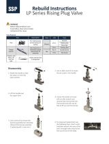
Lock nut
Bonnet
Upper guide
bushing
Bypass
bushing
Spring
Snubber-seat
assembly
Disc
assembly
Stud
Lock nut
O-ring
O-ring
Body

5
2 [50]
7
/
16 - 20 30 - 35 [41 - 48]
3 [80] ½ - 13 45 - 50 [61 - 68]
4 [100] ⅝ - 11 90 - 110 [122 - 149]
6 [150] ¾ - 10 160 - 200 [217 - 271]
8 [200] 1 - 8 305 - 355 [414 - 481]
2 [50] 1⅛ - 18 N-06 40 - 60 [54 - 81]
3 [80] 1¾ - 18 N-09 150 - 190 [203 - 258]
4 [100] 2⅜ - 18 N-12 250 - 300 [339 - 407]
6 [150] 2¾ - 18 N-14 300 - 350 [407 - 474]
8 [200] 4⅜ - 12 AN-22 480 - 550 [651 - 746]
YARWAY 9100 SERIES ARC
®
VALVE
INSTALLATION, OPERATION AND MAINTENANCE INSTRUCTIONS
REASSEMBLY – ALL CLASSES
2" to 8" [50 to 200 mm] valve sizes
1. All parts must be clean prior to reassembly.
2. Torque the upper guide bushing nut to the following values (Table 2) Do not lubricate.
TABLE 2 – UPPER GUIDE BUSHING
Valve Size Nut Size Torque
in. [mm] in. ft/lb [N•m]
3. Install new O-rings on the bypass bushing (use O-ring lube).
4. Important: The hole in the bypass bushing must line up with the bypass port. Use a soft metal
rod to maintain the hole location when torquing the bearing nut.
5. Torque the bearing nut to the bypassing bushing using the torque values listed in Table 3 (use
anti-seize on threads). Bend the lockwasher tab in the slot of the locknut.
LUBRICANTS
Use the following lubricants or their equivalents:
Anti-seize – Loctite 116737 (food grade anti-sieze).
O-ring – Silicone lubricant or liquid soap.
TABLE 3 – BYPASS BUSHING NUT
Valve Size Nut Size Torque
in. [mm] in. ft/lb [N•m]
6. Lap the disc to the body. First use 180 grit (medium coarse) and repeat with 360 grit (fine). The
finished surface should be 360 degrees and a minimum of ½ the available seat width. Clean
thoroughly after each lapping operation.
7. Install the snubber seal assembly in the groove on the disc assembly using O-ring lube. (O-ring
first, followed by Glyd ring.) Heat Glyd ring 140 to 212°F [60 to 100°C] water prior to installation.
Resize ring with hose clamp and shim stock after seal is in groove. Allow to cool 10-20 minutes
to resize.
8. Install the stem/disc assembly into the valve body. Place the spring on the disc. Place bonnet
seal O-ring into the insert O-ring groove. Lower the bonnet, with matchmarks aligned, into
place using care not to damage the snubber seal.
9. Coat studs with anti-seize lubricant prior to assembly. Torque to the values in Table 4.

6
1 - 1½ [25 - 40]
9
/
16 - 12 65 - 70 [88 - 95]
2 [50] ⅝ - 11 70 - 80 [95 - 109]
3 [80] ¾ - 10 120 - 140 [163 - 190]
4 [100] ⅞ - 9 180 - 220 [244 - 298]
6 [150] 1⅛ - 8 450 - 500 [610 - 678]
8 [200] 1¼ - 8 600 - 660 [814 - 895]
1 - 1½ [25 - 40]
7
/
16 [11]
2 [50] ⅝ [16]
3 [80] 1
5
/
16 [24]
4 [100] 1¼ [32]
6 [150] 1½ [38]
8 [200] 2 [50]
1½ [40] 1⅛ - 12 20 - 25 [27 - 34]
2 [50] 1
7
/
16 - 12 45 - 55 [61 - 75]
3 [80] 2⅛ - 12 100 - 120 [136 - 163]
4 [100] 2⅞ - 12 180 - 220 [244 - 298]
6 [150] 4¾ - 12 300 - 340 [406 - 460]
2 [50] ⅛ [3]
3
/
16 [5]
3 [80] ⅛ [3] ¼ [6]
4 [100] ⅛ [3] ⅜ [10]
6 [150] ¼ [6] ½ [13]
8 [200] ¼ [6] ⅝ [16]
YARWAY 9100 SERIES ARC
®
VALVE
INSTALLATION, OPERATION AND MAINTENANCE INSTRUCTIONS
TABLE 4 – BODY BONNET NUTS
Valve Size Nut Size Torque
in. [mm] in. ft/lb [N•m]
10. Check valve stroke by pushing the bottom of the bypass stem with wood or soft metal rod. The
disc assembly must move freely (against spring load) for the entire stroke length. The stroke
length must be as follows:
TABLE 5 – DISC STROKE
Valve Size Stroke Length
in. [mm] in. [mm]
11. For valves with an integral back pressure regulator:
a. Install new regulator capsule, if defective. Lube the O-ring with O-ring lubricant and install
the back pressure regulator capsule into the body.
b. Install the spiral ring into the body groove (lubricate bottom side with Anti-Seize).
c. Coat exposed threads with a thread locking adhesive appropriate for the valve service
temperatures. Back the retaining ring out to load the back pressure regulator capsule with
the required torque as shown in Table 6. Remove and discard the draw bolt and washer
(used to hold the capsule assembly together.) Stake the plunger guide into the retaining ring.
Do not stake toward the centerline of the back pressure regulator.
TABLE 6 – BPR RETAINING RING (spanner nut)
Regulator Size Nut Size Torque
in. [mm] in. ft/lb [N•m]
12. For valves with a flow conditioner (31), a replacement can be installed and tack welded in
place. Weld four places, 90 degrees apart. See Table 7 for weld size and width.
TABLE 7
Valve Size Weld Size Weld Width
in. [mm] in. [mm] in. [mm]

7
YARWAY 9100 SERIES ARC
®
VALVE
INSTALLATION, OPERATION AND MAINTENANCE INSTRUCTIONS
1" to 1 ½" [25 to 40 mm] valve sizes
1. All parts must be clean prior to reassembly.
2. Insert the bypass bushing without the O-ring
in the valve body to guide the disc during the
lapping. Lap the disc to the body per step 6
above.
3. Install the snubber seal assembly (42) in the
groove on the disc (33) per step 7 above.
4. Assemble the disc-bypass bushing parts
(Items 33, 34, 36, 37, 38, 39, 40, and 42)
as follows. Assemble all parts except the
spiral ring (38) and lay the assembly on a
flat surface with the bottom of the disc up.
Compress the spring by pushing down on
the spring retainer until the groove in the
bottom of the disc is exposed. Install the
spiral ring (38) by separating the coils and
inserting one end of ring into groove and
spiral each turn progressively over the shaft.
Slowly release the load on the retainer.
5. To prepare the disc-bypass bushing
assembly for installation in the valve body,
the spring (37) must be compressed and
restrained. There are two spring restraining
methods, one uses a tool and the other a
dowel pin. Using the disc-bypass bushing
assembly illustrations as a guide, visually
compare the parts to the illustrations and
determine if the provisions are for the old or
new method. The old method has a hole in
both the disc and bypass bushing to accept
a tool. The new method has only a hole in
the disc for a dowel pin. Both types of spring
restrainers will be held in place by the spring
load. Prepare the disc-bypass bushing
assembly for installation in the valve body as
described by 5a or 5b below as applicable.
a. For the old restraining method, a tool
must be fashioned by bending a metal
rod as shown. Compress and rotate the
disc and bypass bushing together to align
the assembly holes. Insert the spring
restrainer tool in the assembly holes and
release the spring load.
b. For the new restraining method, provide
the dowel pin as shown. Compress the
disc and bypass bushing together until
the pin assembly hole is exposed. Insert
the spring restrainer pin in the assembly
hole and release the spring load.
6. Visually align the centerline of the threaded
outlet hole in the bypass bushing (34) with
the body bypass outlet hole centerline.
Insert the disc-bypass bushing in the body
carefully so as not to knock the spring
restrainer loose.
7. Rotate and push or pull on the disc to
accurately align the bypass outlet holes.
Shine a light in the bottom of the disc hole
while looking through the body bypass outlet
to check alignment.
8. Install the bypass tube (35) into the body
outlet, threaded end first. Thread the tube
into the bypass bushing (34) and tighten to
approximately 20 ft/lbs [27 N•m] torque
using a spanner wrench or a 1” x 2” x ⅛”
[25x 50 x 3 mm] thick steel plate. Stake the
body into the bypass tube slots.
9. Remove spring restrainer, tool or dowel
as applicable, by pushing on the bottom of
the disc to release the spring load. The tool
should become loose for removal. The pin
should fall out. Ensure restrainer pin either
falls out or is removed from the valve body
before placing the valve back in service.
10. Lubricate, assemble, and check valve
stroke per steps 9 and 10 under the 2” - 8”
instructions.

8
4
3
18
2
6
5
7
13
10
8
1
9
14
16
15
YARWAY 9100 SERIES ARC
®
VALVE
INSTALLATION, OPERATION AND MAINTENANCE INSTRUCTIONS
All surfaces in contact with one another should be completely coated
with a modurate amount of lubricant. Instert the O-ring into the
groove of the body and completely seat the insert into the body. If
binding occurs, remove the insert and determine the area of
obstruction. Take steps necessary to clear the obstruction.
Disc-bypass bushing assembly
1" to 1½" [25 to 40 mm] valves
Old restraining method New restraining method
PARTS AND MATERIALS
Item Part Material
1 Body ASTM A351 type CF8M (J92900)
2 Bonnet ASTM A351 type CF8M (J92900)
3
[2]
Disc ASTM A479 type S21800A
(Nitronic 60 bar)
4
[1][2]
Snubber-seal assembly Turcite 51 (Glyd ring) and
TFE/Propylene (O-ring)
5
[2]
Bypass bushing ASME SA564 Grade 630
(17-4 PH Bar) Condition SA (S17400)
6
[1][2]
O-ring TFE/Propylene
7
[1][2]
O-ring TFE/Propylene
8
[1][2]
Spiral ring Inconel X-750
9
[1][2]
Bypass tube ASTM A312 type 304
10 Spring retainer ASME SA479 type 316
13
[2]
Spring 17-7 PH Condition CH-900
14
[1][2]
O-ring TFE/Propylene
15 Stud ASTM A193 Grade B7 (G41400)
16 Nut ASTM A194 Grade 2H (K04002)
18 Nameplate 300 series stainless steel
NOTES
1. Recommended spare parts for service inspection.
2. Recommended spare parts for service overhaul.
Spring
retainer tool
1
/
16" diameter rod
3
/
8" both ends
5"
Spring
retainer
dowel

9
2
11
10
12
4
3
5
6
7
8
9
1
18
14
13
20
16
15
Bypass with back pressure regulator installed **
2" to 8" [50 to 200 mm] valves
YARWAY 9100 SERIES ARC
®
VALVE
INSTALLATION, OPERATION AND MAINTENANCE INSTRUCTIONS
Neither Emerson, Emerson Automation Solutions, nor any of their affiliated entities assumes responsibility for the selection, use or maintenance of any product.
Responsibility for proper selection, use, and maintenance of any product remains solely with the purchaser and end user.
Yarway is a mark owned by one of the companies in the Emerson Automation Solutions business unit of Emerson Electric Co. Emerson Automation Solutions, Emerson
and the Emerson logo are trademarks and service marks of Emerson Electric Co. All other marks are the property of their respective owners.
The contents of this publication are presented for informational purposes only, and while every effort has been made to ensure their accuracy, they are not to be
construed as warranties or guarantees, express or implied, regarding the products or services described herein or their use or applicability. All sales are governed by
our terms and conditions, which are available upon request. We reserve the right to modify or improve the designs or specifications of such products at any time without
notice.
Emerson.com/FinalControl
PARTS AND MATERIALS
Item Part Material
1 Body ASTM A-216 Grade WCB
2 Bonnet ASTM A-216 Grade WCB
3
[2]
Disc assembly
(bypass element)
2” to 6”: ASTM A351 type CF10SMnN
(Nitronic60 Cast)
8” to 12”: ASTM A351 type CF8M disc with
ASTM A479 type A21800A stem
4
[1][2]
Snubber-seal
assembly
Turcite 51 (Glyd ring) and
TFE/Propylene (O-ring)
5
[2]
Bypass bushing ASTM A747 Grade CB7Cu-1
(17-4PH Cast) Condition H900 (J92180)
6
[1][2]
O-ring TFE/Propylene
7
[2]
Lock washer ASTM A194 Grade 8 (18-8)
8
[2]
Lock nut Stainless steel 18-8
9
[1][2]
O-ring TFE/Propylene
10
[2]
Upper guide
bushing
ASTM A747 Grade CB7Cu-1
(17-4 PH Cast) Condition A
11
[2]
Lock nut 300 series stainless steel
12
[2]
Snubber orifice Stainless steel 18-8
13
[2]
Spring 17-7 PH Condition CH-900
14
[1][2]
O-ring TFE/Propylene
15 Stud ASTM A193 Grade B7 (G41400)
16 Nut ASTM A194 Grade 2H (K04002)
18 Nameplate 300 series stainless steel
20 Flow conditioner
(600 class only)
ASTM A351 type CF8M
NOTES
1. Recommended spare parts for service inspection.
2. Recommended spare parts for service overhaul.
** Back Pressure Regulator spare parts available only as a replacement
capsule (parts 21 to 30).
/