
©Aug. 2020 by Shimano Inc. ITP
Ver.1.1
SERVICE MANUAL
SG-C3001-7R
SG-C3001-7C
SG-C3001-7C
SG-C3001-7D
-DX

1
Introduction of INTER-7
……………………………………………………………………………………………………
2
Dealer's Manual
………………………………………………………………………………………………………………………
4
SG-C3001-7R, SG-C3001-7C, SG-C3001-7C-DX, SG-C3001-7D
• INSTALLATION
• ADJUSTMENT
• MAINTENANCE
Troubleshooting
………………………………………………………………………………………………………………………
37
Disassembly & Assembly
………………………………………………………………………………………………
41
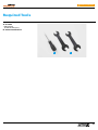
Required Tools
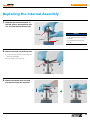
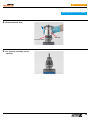
Replacing the Internal Assembly
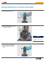
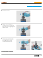
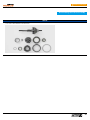
Disassembling the Internal Assembly
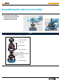
Assembling the Internal Assembly
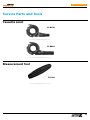
Service Parts & Tools
…………………………………………………………………………………………………………
54
Cassette Joint
Measurement Tool
Application chart
Interchangeability
…………………………………………………………………………………………………………………
57
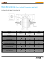
Hub dimensions
(Over Locknut Dimensions and Axle)
…………………………………
59
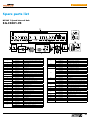
EV / Spare Parts List
………………………………………………………………………………………………………………
61
CONTENTS

2
Return to index page
SG-C3001-7R SG-C3001-7C SG-C3001-7DSG-C3001-7C-DX
SG-C3001-7R
Internal Geared Hub for Roller Brake (7-speed)
• Improved internal gear engagement that allows
for a smoother ride
• New, updated and polished design that
complements the bike
»Aluminum hub shell
• Color options: Black, Silver
SG-C3001-7C
Internal Geared Hub for Coaster Brake (7-speed)
• Improved internal gear engagement that allows
for a smoother ride
• New, updated and polished design that
complements the bike
»Steel hub shell
• Deluxe version (SG-C3001-7C-DX)
• Color options: Black, Silver
SG-C3001-7D
Internal Geared Hub for Disc Brake (7-speed)
• Improved internal gear engagement that allows
for a smoother ride
• New, updated and polished design that
complements the bike
»Aluminum hub shell
• Disc version for sportier-styled bikes
»Disc brake specication for a greater variety of
bikes
• CENTER LOCK
• Color options: Black, Silver
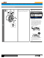
The CENTER LOCK system makes an easy disc brake rotor installation possible with
spline mount and a lock ring.
The lock ring mounting system reduces the total workinghours by shortening
the amount of time of bothinstallation and de-installation. In addition, the
securefixing by the spline mount enhances precision and rigidity while improving
braking efficiency.
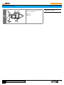
TECHNOLOGIES
Disc brake rotor spline
Disc brake rotor
Lock ring
CENTER LOCK System
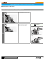
Coaster Brake
The SHIMANO NEXUS coaster brake is operated by pedaling backward in a similar
way as ordinary types. Its uniqueness is that braking power transmitted to the
wheel directly for the SHIMANO NEXUS internal coaster brake is independent of
the gear shifting mechanism built into the hub. Also it always generates the same
braking force regardless of gear position to actualize comfortable and reliable
riding. It actualizes the braking force to meet the ISO 4210 standard.
Hub shell
Sprocket
Brake shoe
Brake roller Braking cam
Actuator
Equal braking force in each gear
1.5
1.0
2.0
0.5
3-RETNI dna ,7-RETNI ,8-RETNI
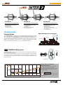
Wide-Range Gearing
QUICK
TIP
CAUTION
148%
low-high
difference
244%
low-high
difference
307%
low-high
difference
1st
dn2
dr3 ht4
ht5
ht6 ht7 ht8
0.73(27T)
)T02(00.1
)T51(63.1
)T23(36.0
)T72(47.0
)T42(48.0
)T02(99.0
)T71(51.1
)T51(43.1
)T31(55.1
)T83(35.0
)T13(46.0
)T72(57.0
)T42(58.0
)T02(00.1
)T61(22.1
)T41(24.1
)T21(16.1
INTER-3
7-RETNI
8-RETNI
The table at the left shows the relative gear
ratio when used with a 20T sprocket.
The numbers in parenthesis show the sprocket
size that each gear ratio corresponds to
in a
derailleur system.
Please use a non-turn washer to secure
the hub axle into the dropout of the
frame.

3
Return to index page
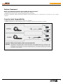
Surface Treatment
• The Standard version is designed to use under normal climate conditions.
• The DX version features a clear coated finish and/or stainless steel material.
This finish is offering an advanced protection against corrosion and is therefore recommended to use under more severe climate
conditions.
What is the difference between the Standard and the DX version?
Question: What is the function of the Cassette Joint (CJ)?
Answer:
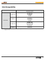
Cassette Joint Compatibility
• CJ-NX10: Standard cable sealing performance, chain case compatible
• CJ-NX40: Scandinavian spec cable sealing performance, strongly recommended for cold climate conditions
The Cassette Joint transforms the linear movement of the shifting cable into a rotation of the
shifting sleeve to shift the gear to a selected gear. The CJ is assembled on the right hand side of the
hub and has a “hook in part” for the inner cable fixing bolt. It comes with a fixing ring for assembly
and a driver cap for sealing.


5
https://si.shimano.com/DM/CASG001
Dealer’s Manual (SG-C3001-7R / SG-C3001-7C / SG-C3001-7C-DX / SG-C3001-7D)
Return to index page
Click here for the latest Dealer's Manual
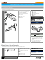
INSTALLATION
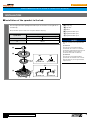
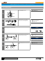
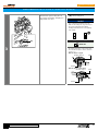
Installation of the sprocket to the hub
Place the right-hand dust cap B/right-hand dust cap C onto the driver on the right side of
the hub body.
Next, install the sprocket and secure it in place with the snap ring.
(A)
Snap ring
(B)
Sprocket
(C)
Driver
(D)
Right-hand dust cap C
(E)
Right-hand dust cap B
(F)
Right-hand dust cap A
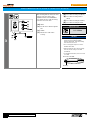
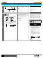
NOTICE
Note the orientation of the right-hand dust
cap.
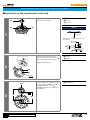
Specification A
If the sprocket is an inward assembling
sprocket with 19T or fewer or for belt drive
specifications, right-hand dust cap A will come
into contact with the chain or pulley so
specification B should be used instead.
Specification B
If the sprocket is an inward assembling
sprocket with 16T and 3mm teeth or for belt
drive specifications, remove right-hand dust
cap B before use.
Specifications
Applicable sprockets
Outward assembling Inward assembling
A
16T-23T
20T-23T
B
16T-23T
(A)
(B)
(C)
(F)
Specification A Specification B
Specification A Specification B
(D) (E)

6
https://si.shimano.com/DM/CASG001
Dealer’s Manual (SG-C3001-7R / SG-C3001-7C / SG-C3001-7C-DX / SG-C3001-7D)
Return to index page
Click here for the latest Dealer's Manual
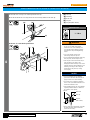
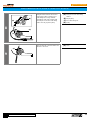
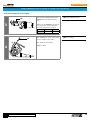
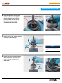
Installation of the cassette joint to the hub
1
(B)
(A)
(C)
Install the driver cap to the driver on the
right side of the hub body.
(A)
Driver cap
(B)
Driver
(C)
Sprocket
NOTICE
Note the orientation of the driver cap.
Driver side
Install the driver cap in the position shown in
the illustration.
Sprocket
Snap ring
Driver cap
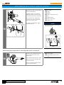
2
(A)
(B)
(z)
Turn the cassette joint pulley in the
direction of the arrow to align the red
marks on the pulley and the bracket.
(z)
Should be aligned
(A)
Pulley
(B)
Bracket
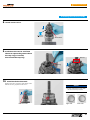
3
(z)
(A)
(z)
Install it with the red marks (z) on the
cassette joint aligned with the red
(SG-C6001/SG-C6011) or yellow
(SG-C3001) marks (z) on the right side of
the hub body.
(A)
Cassette joint

7
https://si.shimano.com/DM/CASG001
Dealer’s Manual (SG-C3001-7R / SG-C3001-7C / SG-C3001-7C-DX / SG-C3001-7D)
Return to index page
Click here for the latest Dealer's Manual
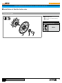
4
LOCK
(z)
(A)
(B)
Secure the cassette joint to the hub with
the cassette joint mounting ring.
When installing the cassette joint
mounting ring, align the yellow mark
(z) with the yellow mark (z) on the
pulley of the cassette joint.
(A)
Cassette joint mounting ring
(B)
Pulley
5
LOCK
(A)
Turn the cassette joint mounting ring 45°
clockwise.
(A)
Cassette joint mounting ring
NOTICE
Hold down the cassette joint bracket securely
when performing work.

8
https://si.shimano.com/DM/CASG001
Dealer’s Manual (SG-C3001-7R / SG-C3001-7C / SG-C3001-7C-DX / SG-C3001-7D)
Return to index page
Click here for the latest Dealer's Manual
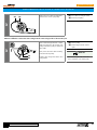
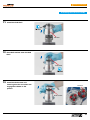
Installing the Inter-M brake to the hub body
(z)
(A) (B)(C)
Engage the hub body splines (z) with the
INTER M brake splines (z), and then
tighten with the brake unit fixing
washer.
(A)
Inter-M brake
(B)
Hub body
(C)
Brake unit fixing washer
Installation of the hub to the frame
1
(A)
(B)
Mount the chain on the sprocket, and
then set the hub axle into the fork end.
(A)
Hub axle
(B)
Fork end

9
https://si.shimano.com/DM/CASG001
Dealer’s Manual (SG-C3001-7R / SG-C3001-7C / SG-C3001-7C-DX / SG-C3001-7D)
Return to index page
Click here for the latest Dealer's Manual
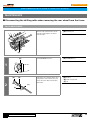
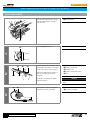
2
Place non-turn washers and onto the right and left sides of the hub axle.
At this time, turn the cassette joint so that the protrusions of the non-turn washers fit into
the grooves in the fork ends and align the joint to be almost parallel to the chainstay.
(A)
Non-turn washer (for left-side use)
(B)
Groove in fork end
(C)
Cassette joint
(D)
Chainstay
(E)
Non-turn washer (for right-side
use)
NOTICE
When installing parts such as a mudguard stay
to the hub axle, install them in the order
shown in the illustration below.
Non-turn washer
Mudguard stay
Carrier stay
Washer
Cap nut
(A)
(E)
(D)(C)
(B)
TECH TIPS
•
The protrusion should be on the fork end side.
•
Install the non-turn washer so that the protrusion fits securely in the fork end groove at the front and back sides of the hub axle.
•
Use a non-turn washer that matches the shape of the fork end. Different non-turn washers are used for the left and right sides.
Fork end
Non-turn washer
Mark/Color
Size
For right For left
Standard
5R/Yellow 5L/Brown ϴ ≤20°
7R/Black 7L/Gray 20°≤ ϴ ≤38°
Reversed 6R/Silver 6L/White ϴ =0°
Reversed
(Full chain case)
5R/Y
ellow 5L/Brown ϴ =0°
Vertical 8R/Blue 8L/Green ϴ =60° - 90°
Note: Vertical type does not include the coaster specifications
θ
Mark

10
https://si.shimano.com/DM/CASG001
Dealer’s Manual (SG-C3001-7R / SG-C3001-7C / SG-C3001-7C-DX / SG-C3001-7D)
Return to index page
Click here for the latest Dealer's Manual
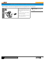
In the case of Inter-M brake specifications
2
(A)
(B)
(C)
(D)
Attach the brake arm of the Inter-M
brake to the chainstay with the brake
arm clip.
Next, temporarily fix the clip bolt and
clip nut by lightly tightening them.
(A)
Brake fixing washer
(insert manually)
(B)
Clip nut
(C)
Arm clip
(D)
Clip bolt (M6 × 16mm)
NOTICE
Check that the brake unit is firmly secured to
the hub with the brake unit fixing washer.
TECH TIPS
If the hub nuts are cap nuts, use a frame with
fork ends that are at least 7mm thick.
3
(A)
Take up slack in the chain and secure the
wheel to the frame with the cap nut.
(A)
Hub nut
Tightening torque
30 - 45 N·m
NOTICE
Check that the wheel is fixed securely to the
frame with the hub nut.

11
https://si.shimano.com/DM/CASG001
Dealer’s Manual (SG-C3001-7R / SG-C3001-7C / SG-C3001-7C-DX / SG-C3001-7D)
Return to index page
Click here for the latest Dealer's Manual
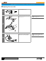
4
Fix the brake arm securely to the chainstay with the arm clip.
Check that the brake arm is securely fastened to the chainstay with the brake arm clip.
(A)
Arm clip
(B)
Chainstay
(C)
Brake arm
(D)
Clip nut
(E)
Clip bolt (M6 × 16mm)
Tightening torque
2 - 3 N·m
WARNING
•
When securing the brake arm to the frame,
be sure to use a brake arm clip that
matches the size of the chainstay, and
securely tighten them with the clip bolt
and clip nut to the specified tightening
torque.
•
Use a lock nut with a nylon insert
(self-locking nut) as the clip nut.
•
It is recommended that Shimano made clip
bolts, clip nuts, and arm clips be used.
•
If the clip nut comes off the brake arm, or
if the clip bolt or arm clip becomes
damaged, the brake arm may rotate on the
chainstay and cause the handlebars to jerk
suddenly, or the bicycle wheel may lock
and the bicycle may fall over, causing
serious injury.
NOTICE
•
If it is not installed correctly, braking
performance will suffer. Be careful not to
apply excessive force when installing.
•
If excessive force is applied to the brake
arm to secure it, the wheel will make noise
and become difficult to turn.
•
After installing the arm clip, check that the
clip bolt protrudes about 2 to 3mm from
the end face of the clip nut.
Clip nut
Brake arm
Arm clip
Clip bolt
(M6 × 16mm)
2 - 3mm
•
Before using the Coaster Brake, check that
the brake works properly and that the
wheel turns smoothly.
(A)(B)
(C)
In the case of coaster brake specifications
(D)(C) (E)
(A)(B)

12
https://si.shimano.com/DM/CASG001
Dealer’s Manual (SG-C3001-7R / SG-C3001-7C / SG-C3001-7C-DX / SG-C3001-7D)
Return to index page
Click here for the latest Dealer's Manual
Installation of the disc brake rotor
Center lock type
(A) (B) (C)
(A)
Disc brake rotor
(B)
Disc brake rotor fixing lock ring
(C)
TL-LR10
Tightening torque
40 N·m

13
https://si.shimano.com/DM/CASG001
Dealer’s Manual (SG-C3001-7R / SG-C3001-7C / SG-C3001-7C-DX / SG-C3001-7D)
Return to index page
Click here for the latest Dealer's Manual
5 bolt type (with lock washer)
1
(A)
(B)
Attach the disc brake rotor and the disc
brake rotor lock washers to the hub, and
then tighten them on with the bolts.
(A)
Lock washer
(B)
Disc brake rotor fixing bolt
Tightening torque
2 - 4 N·m
NOTICE
•
Fit the lock washers so that the marking
"TOP" is visible.
•
Ensure that the hooked parts of the lock
washer are securely caught on the notches
in the disc brake rotor and then tighten on
the lock washer with the disc brake rotor
fixing bolt. If tightened while the hooked
parts are against the surface of the disc
brake rotor, the washer and its hooked
parts will become deformed.
Hooked part of washer
Notch in disc brake rotor
•
The lock washers are not reusable. Always
use new lock washers when installing/
re-installing the disc brake rotor.
•
Use the dedicated disc brake rotor fixing
bolts.

14
https://si.shimano.com/DM/CASG001
Dealer’s Manual (SG-C3001-7R / SG-C3001-7C / SG-C3001-7C-DX / SG-C3001-7D)
Return to index page
Click here for the latest Dealer's Manual
2
Wear gloves and turn the disc brake
rotor clockwise with some force.
At this time, tighten on the disc brake
rotor fixing bolts in the order indicated
in the illustration.

15
https://si.shimano.com/DM/CASG001
Dealer’s Manual (SG-C3001-7R / SG-C3001-7C / SG-C3001-7C-DX / SG-C3001-7D)
Return to index page
Click here for the latest Dealer's Manual
Installation of the lever
When equipped with mode switching mechanism
1
Use screwdriver[#1] to loosen the screw.
2
Set the mode switch to the mode
position for the brake installed.
TECH TIPS
For V-BRAKE brakes
For caliper brakes/cantilever brakes/roller
brakes

16
https://si.shimano.com/DM/CASG001
Dealer’s Manual (SG-C3001-7R / SG-C3001-7C / SG-C3001-7C-DX / SG-C3001-7D)
Return to index page
Click here for the latest Dealer's Manual
Installation of the lever
Install the lever as shown in the illustration.
(B)
(C)
(A)
(D)
(y)
(z)
(z)
(A) (B)
(C)
(E)
Pass the lever over the handlebar and
then attach the grip/half grip.
Tighten the fixing bolt with a 5mm
hexagon wrench.
(y)
166mm or more
(z)
Ø22.2mm
(A)
Fixing bolt
(B)
Handlebar
(C)
5mm hexagon wrench
(D)
Half grip
(E)
Grip
Tightening torque
6 - 8 N·m
NOTICE
When using SL-C6000/SL-C3000, make sure to
install the handlebar with the grip spacer
attached.
Grip spacer
TECH TIPS
•
If using Shimano half grip, the straight
section of the handlebar should be 166mm
or longer.
Attach the REVOSHIFT lever to this straight
section.
•
Leave a gap of 0.5mm between the
REVOSHIFT lever and the half grip.
Installation of the shifting cable
For information on how to replace the inner cable, refer to the maintenance section.
(y) (z)
(A)
Use a shifting cable with one inner cable
drum.
Shifting cable with one inner cable
drum:
OT-SP41
(y)
Shifting lever side
(z)
Cassette joint side
(A)
Sealed outer cap
NOTICE
Make sure that the sealed outer cap is at the
shifting lever end.

17
https://si.shimano.com/DM/CASG001
Dealer’s Manual (SG-C3001-7R / SG-C3001-7C / SG-C3001-7C-DX / SG-C3001-7D)
Return to index page
Click here for the latest Dealer's Manual
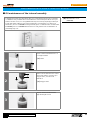
Installing to the cassette joint
For CJ-NX10/CJ-8S20
1
(z)
(A) (B)
Pass the inner cable through the OT-SP41
outer casing to the end with the plastic
cap.
(z)
Lever side
(A)
Aluminum cap
(B)
Plastic cap
TECH TIPS
Cutting the outer casing
If cutting the outer casing, cut it near the end
with the plastic cap while the cap is still
attached.
Plastic cap
After cutting, make the cut end perfectly
round and attach the plastic cap.
2
(A)
Set the REVOSHIFT lever to 1.
(A)
REVOSHIFT lever

18
https://si.shimano.com/DM/CASG001
Dealer’s Manual (SG-C3001-7R / SG-C3001-7C / SG-C3001-7C-DX / SG-C3001-7D)
Return to index page
Click here for the latest Dealer's Manual
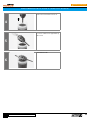
3
(w)
(y)
(z)
(x)
(A)
(B)
(C)
(D)
After checking that the end of the outer
casing is securely set in the cable
adjustment barrel of the REVOSHIFT
lever, attach the inner cable mounting
bolt unit to the inner cable.
(w)
10mm
(x)
Pass the inner cable through the
hole.
(y)
101mm
(z)
Pull the inner cable when
securing.
(A)
Inner cable mounting nut (Black)
(B)
Inner cable mounting washer
(Silver)
(C)
Inner cable mounting bolt (Silver)
(D)
Inner cable mounting bolt unit
Tightening torque
3.5 - 5.5 N·m
NOTICE
•
This inner cable mounting bolt unit is
designed only for CJ-NX10, CJ-NX40,
CJ-8S20, and CJ-8S40. 11-speed mounting
bolt units cannot be used.
•
The tool is shipped ready to be used for
CJ-NX10 and CJ-8S20.
•
When installing the inner cable mounting
bolt unit, use the setting tool TL-CJ40
(Y70898020).
•
For CJ-NX10 and CJ-8S20, use the front side
of TL-CJ40.
Nut fitting
Front side of TL-CJ40

19
https://si.shimano.com/DM/CASG001
Dealer’s Manual (SG-C3001-7R / SG-C3001-7C / SG-C3001-7C-DX / SG-C3001-7D)
Return to index page
Click here for the latest Dealer's Manual
4
LOCK
(C)
(D)
(A)
(B)
Bring the cable around to the cassette
joint pulley, hold it so that the inner
cable fixing nut is facing outwards
(towards the fork end), and then slide
the flats part of the inner cable fixing
washer into the gap in the pulley.
(A)
Flats part of inner cable fixing
washer
(B)
Gap in pulley
(C)
Inner cable fixing nut
(D)
Pulley
5
LOCK
(A)
Turn the cable 60° counterclockwise and
attach it to the hook.
(A)
Hook
Page is loading ...
Page is loading ...
Page is loading ...
Page is loading ...
Page is loading ...
Page is loading ...
Page is loading ...
Page is loading ...
Page is loading ...
Page is loading ...
Page is loading ...
Page is loading ...
Page is loading ...
Page is loading ...
Page is loading ...
Page is loading ...
Page is loading ...
Page is loading ...
Page is loading ...
Page is loading ...
Page is loading ...
Page is loading ...
Page is loading ...
Page is loading ...
Page is loading ...
Page is loading ...
Page is loading ...
Page is loading ...
Page is loading ...
Page is loading ...
Page is loading ...
Page is loading ...
Page is loading ...
Page is loading ...
Page is loading ...
Page is loading ...
Page is loading ...
Page is loading ...
Page is loading ...
Page is loading ...
Page is loading ...
Page is loading ...
Page is loading ...
Page is loading ...
Page is loading ...
Page is loading ...
-
 1
1
-
 2
2
-
 3
3
-
 4
4
-
 5
5
-
 6
6
-
 7
7
-
 8
8
-
 9
9
-
 10
10
-
 11
11
-
 12
12
-
 13
13
-
 14
14
-
 15
15
-
 16
16
-
 17
17
-
 18
18
-
 19
19
-
 20
20
-
 21
21
-
 22
22
-
 23
23
-
 24
24
-
 25
25
-
 26
26
-
 27
27
-
 28
28
-
 29
29
-
 30
30
-
 31
31
-
 32
32
-
 33
33
-
 34
34
-
 35
35
-
 36
36
-
 37
37
-
 38
38
-
 39
39
-
 40
40
-
 41
41
-
 42
42
-
 43
43
-
 44
44
-
 45
45
-
 46
46
-
 47
47
-
 48
48
-
 49
49
-
 50
50
-
 51
51
-
 52
52
-
 53
53
-
 54
54
-
 55
55
-
 56
56
-
 57
57
-
 58
58
-
 59
59
-
 60
60
-
 61
61
-
 62
62
-
 63
63
-
 64
64
-
 65
65
-
 66
66


Shimano SG-C3001-7C User manual
- Type
- User manual
- This manual is also suitable for
Ask a question and I''ll find the answer in the document
Finding information in a document is now easier with AI
Related papers
-
Shimano CJ-7S40 Service Instructions
-
Shimano ST-TX800 Exploded View
-
Shimano BL-T785 Exploded View
-
Shimano CJ-NX40 Service Instructions
-
Shimano SG-C3000-7C-DX Exploded View
-
Shimano BL-M820 Exploded View
-
-
-
-
Other documents
-
König KN-PVA10 Datasheet
-
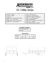 Anderson Manufacturing EC Utility Series User manual
-
Global Industrial 293224 User manual
-
 CRANACH Barrel Bolt User manual
-
Bontrager 231793 User manual
-
Porter-Cable C3001 User manual
-
 AMLAD CYKLER SENIOR BIKE Assembly & Instruction Manual
-
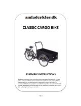 AMLAD CYKLER Classic Cargo Bike Assembly & Instruction Manual
-
MTD 117-071-000 User manual
-
 AMLAD CYKLER SENIOR BIKE Assemble Instructions


