Pulsar PSDCS161214 Operating instructions
- Type
- Operating instructions

PSDCS161214
v.1.0
PSDCS 12V/14A/16x1A/TOPIC
Two-section power supply for up to 16 HD cameras (2x8)
EN**
Edition: 1 from 12.06.2017
Supersedes the edition: ------------

www.pulsar.pl PSDCS161214
2
Features:
the 16x0,87A/12V DC power output for powering
16 HD cameras
two independent, galvanically isolated power
sections
the output voltage can be adjusted in the range
12V÷15V DC separately for each section
16 outputs protected with 1A fuses
wide range of supply voltage 176÷264VAC
high efficiency 84%
LED indication
protections:
SCP short-circuit protection
OVP over voltage protection
surge protection
OLP overload protection
warranty – 2 year from the production date
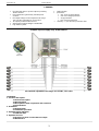
Example of power supply of up 16 HD cameras.
All channels adjustable in the range 12V÷15V DC, 16 x 0,87A
CONTENTS:
1. Technical description.
1.1 General description
1.2 Block diagram
1.3 Description of PSU components and connectors
1.4 Specifications
2. Installation.
2.1 Requirements
2.2 Installation procedure
3. Operating status indication.
3.1 LED indication
4. Operation and use.
4.1 Overload or short circuit at the PSU output
4.2 Maintenance

www.pulsar.pl PSDCS161214
3
1. Technical description.
1.1 General description.
The PSDCS161214 stabilized power supply is designed to supply HD cameras or other devices requiring
stabilized voltage of 12V DC. The power supply unit features 16 outputs divided into two independent, galvanically
isolated power sections. The output voltage of all power supply sections can be independently adjusted by a
potentiometer in the range 12V ÷ 15V DC. The outputs are independently protected by melting fuses. A failure (a short
circuit) in the output circuit makes a fuse blow and disconnection of the circuit from the DC power supply (+U). The PSU
is housed in a metallic enclosure with an indication panel featuring.
1.2. Block diagram (fig.1).
Fig.1. Block diagram of the PSU.
1.3. Description of PSU components and connectors.
Table 1. Elements of the PSU pcb (see fig. 2).
Element no.
Description
[1]
L1…L8 (green) LEDs (indicating fuse activation)
[2]
F1…F8 glass fuses in AUX (+) circuits
[3]
IN supply input of the LB8 strip
[4]
AUX1…AUX8 outputs, COM (-) shared terminal
Fig. 2. The view of the PSU’s pcb.

www.pulsar.pl PSDCS161214
4
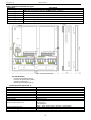
Table 2. Elements of the PSU (see fig. 3).
Element no.
Description
[1]
L-N 230V AC power connectors, PE protection connector
[2]
F fuse in the supply circuit (230V AC)
[3]
PSU module
[4]
V
ADJ
, potentiometer, output voltage adjustment within the range of 12V÷15V DC
[5]
LED indication of DC power status, main module of the PSU
[6]
LB8/A fuse strip, with power outputs and LED indication
[7]
LB8/B fuse strip, with power outputs and LED indication
Fig.3. The view of the PSU.
1.4. Specifications:
- electrical specifications (tab.3)
- mechanical specifications (tab.4)
- operation safety (tab.5)
- operating specifications (tab.6)
Electrical specifications (tab. 3).
Supply voltage
176 ÷ 264V AC
Current consumption
1,6A@230VAC max.
PSU power
168W max.
Efficiency
84%
Output voltage
12V DC
Output current
16x 0,87A (Σ I = 14A) max. @12V
Output voltage adjustment range
12V÷15V DC
Ripple voltage
100mV p-p max.
Short-circuit protection SCP
LB8 (A, B) STRIP
16x F 1A fuse
PSU MODULE
105% ÷ 150% of PSU power, electronic current limiting
Overload protection OLP
105% ÷ 150% of PSU power, electronic current limiting
Surge over voltage protection OVP
>16V (automatic recovery)
F1÷ F16 fuses
F 1A/250V

www.pulsar.pl PSDCS161214
5
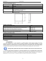
Mechanical specifications (tab. 4).
Dimensions
W=300, H=301, D+ D
1
=52+8 [+/- 2mm]
W
1
=305, H
1
=306 [+/- 2mm]
Fixing
See figure 3
Net/gross weight
2,7/2,9 kg
Enclosure
Steel plate, DC01 0,7mm colour: RAL 9003
Closing
Cheese-head screw: at the front
Connectors
Power supply: 230V AC: Φ0,63-2,05 (AWG 22-12)
AUX outputs: Φ0,51- 2,05 (AWG 24-12)
LB8: Φ0,51- 2,05 (AWG 24-12)
Notes
The enclosure does not adjoin the assembly surface so that cables can be led.
Convectional cooling.
Operation safety (tab.5).
Protection class EN 60950-1:2007
I (first)
Protection grade EN 60529: 2002 (U)
IP20
Electrical strength of insulation:
- between input (network) circuit and output circuits of the PSU (I/P-O/P)
- between input circuit and PE protection circuit (I/P-FG)
- between output circuit and PE protection circuit (O/P-FG)
3000V/AC min.
1500V/AC min.
500V/AC min.
Insulation resistance:
- between input circuit and output or protection circuit
100 MΩ, 500V/DC
Operating specifications (tab.6).
Operating temperature
-10ºC...+40ºC
Storage temperature
-25ºC...+60ºC
Relative humidity
20%...90%, without condensation
Vibrations during operation
unacceptable
Impulse waves during operation
unacceptable
Direct insolation
unacceptable
Vibrations and impulse waves during transport
PN-83/T-42106
2. Installation.
2.1 Requirements.
The stabilized PSU is to be mounted by a qualified installer, holding relevant permits and licenses
(applicable and required for a given country) for 230V/AC interference and low-voltage installations. The unit
should be mounted in confined spaces, in accordance with the 2nd environmental class, with normal relative
humidity (RH=90% maximum, without condensation) and temperature from -10°C to +40°C. The PSU shall work in
a vertical position that guarantees sufficient convectional air-flow through ventilating holes of the enclosure.
During normal operation the total current consumption of the receivers cannot exceed I=14A
As the PSU module is designed for a continuous operation and is not equipped with a power-switch,
therefore an appropriate overload protection shall be guaranteed in the power supply circuit. Moreover, the user
shall be informed about the method of unplugging (most frequently through separating and assigning an
appropriate fuse in the fuse-box). The electrical system shall follow valid standards and regulations.

www.pulsar.pl PSDCS161214
6
2.2 Installation procedure.
1. Before installation, make sure that the voltage in the 230V power-supply circuit is cut off.
2. Mount the PSU in a selected location and connect the wires.
3. Connect the power cables (~230VAC) to L-N terminals of the PSU. Connect the ground wire to the terminal
marked by the earth symbol. Use a three-core cable (with a yellow and green PE protection wire ) to make the
connection. Lead the cables to the appropriate terminals of the connection board through the bushing.
The shock protection circuit shall be performed with a particular care, i.e. the yellow
and green wire coat of the power cable shall stick to one side of the terminal marked with the
‘ ’ earth symbol in the PSU enclosure. Operation of the power supply without a properly
made and fully operational shock protection circuit is UNACCEPTABLE! It can result in device
damage or an electric shock.
4. Connect the receivers’ cables to the AUX1…AUX8 connectors on the LB8 (A, B) strips.
5. In electrical installations with significant voltage drops in the resistance of the wires that lead to the receivers, the
voltage value can be corrected with the P1 potentiometer (12V÷15V DC) – independently for each section.
6. Check the PSU operating status indication
7. Once the installation and operation control have been completed, the enclosure can be locked.
3. Operating status indication.
The PSU is equipped with LED indication of operation status. The presence of voltage at the input of LB8
strips is indicated by green LEDs on the front panel.
3.1. LED indication.
LED1…LED8 LB8-A and LED1…LED8 LB8-B green diodes indicate power at the outputs:
LB8-A AUX1…..AUX8, LB8-B AUX1…..AUX8.
In case of a power loss at the output (fuse activation), an appropriate diode goes out (L1 for AUX1, L2 for AUX2
etc.)
4. Operation and use.
4.1 Overload or short circuit at the PSU output.
The AUX1÷AUX8 PSU outputs of the LB8 (A, B) strips are protected against a short circuit by glass fuses,
replace the fuse (of the same parameters) in case of a failure.
4.2. Maintenance.
Any and all maintenance operations may be performed following the disconnection of the PSU from the
power supply network. The PSU does not require performing any specific maintenance measures. However, in
case of significant dust level, clean its interior with compressed air. In case of a fuse exchange, use the
replacement of the same parameters.
WEEE MARKING
According to the EU WEE Directive – It is required not to dispose of electric or electronic waste
as unsorted municipal waste and to collect such WEEE separately.
Pulsar sp. j.
Siedlec 150, 32-744 Łapczyca, Poland
Tel. (+48) 14-610-19-40, Fax. (+48) 14-610-19-50
http:// www.pulsar.pl, www.zasilacze.pl
-
 1
1
-
 2
2
-
 3
3
-
 4
4
-
 5
5
-
 6
6


Pulsar PSDCS161214 Operating instructions
- Type
- Operating instructions
Ask a question and I''ll find the answer in the document
Finding information in a document is now easier with AI
Related papers
-
Pulsar PSDCR161214 Operating instructions
-
Pulsar PSDC161214 Operating instructions
-
Pulsar PSDC161212T Operating instructions
-
-
Pulsar PSDC08124 Operating instructions
-
Pulsar PSDC08128 Operating instructions
-
-
-
-