Page is loading ...

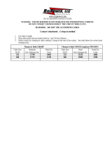
Connector Dimensional Requirements
Minimum Maximum
inches (mm) inches (mm)
Outside Diameter 0.87" (22,1 mm) 2.07" (52,6 mm)
Length
Aluminum (Al/Cu) ------ 7.50" (191 mm)
Length
Copper (Cu) ------ 8.25" (210 mm)
Selection Chart
Kit Number Cable Insulation Conductor
O.D. Range Size Range
5468A-WG 1.24" to 2.07" 350–1000 kcmil*
(31,5 mm to 52,6 mm) (185–500 mm
2
)
Cold Shrink QS-III
Splicing Kit
Instructions
For Concentric Neutral (CN), Jacketed Concentric Neutral (JCN) and Flat Strap Neutral Cable
IEEE Std. 404
35 kV Class
250 kV BIL
* Splices (including size transitions) can be made to smaller or larger conductors (but larger conductors
may require special neutral handling), provided both cables are within the Insulation O.D. Range and
the connector meets the dimensional requirements shown below.
3M
™
Cold Shrink
QS-III Splicing Kit
5468A-WG
78-8126-0345-0-B
CAUTION
Working around energized high-voltage systems may cause serious
injury or death. Installation should be performed by personnel familiar
with good safety practice in handling high-voltage electrical equipment.
De-energize and ground all electrical systems before installing product.
Jacketed Concentric Neutral (JCN)
Flat Strap Neutral
Concentric Neutral (CN)

2
78-8126-0345-0-B
Kit Contents:
Quantity Description
1 ......................5468A-WG Splice Body
2 ......................Tubes of P55/R Compound
1 ......................5468A-WG Splice Instruction
1 ......................Adapter Tube
2 ......................Cable Preparation Templates
4 ......................Scotch
™
2230 Mastic Sealing Strips, 6" length

3
78-8126-0345-0-B
Instructions for Jacketed Concentric Neutral (JCN),
Concentric Neutral (CN), and Flat Strap Neutral Cable
1.0 Prepare Cables
1.1
Prepare cables according to standard procedures. Refer to illustration below for proper dimensions.
Additional distance is required on one cable to provide extra neutral wire length for connecting the neutrals.
“A”
“B”
4 1/2"
(114 mm)
Extra neutral
wire length
Jacketed Concentric Neutral (JCN)
or Flat Strap Neutral
Concentric Neutral (CN)
Concentric Neutral (CN)Jacketed Concentric Neutral (JCN)
or Flat Strap Neutral
“A”
“B”
4 1/2"
(114 mm)
lacipyT
*eziSrotcudnoC
limck
mm(
2
)
noitalusnI
egnaRDO
sehcnI
)mm(
kcabtuCtekcaJ
”A“
sehcnI
)mm(
kcabtuCnoc-imeS
”B“
sehcnI
)mm(
005–**053
)003–581(
07.1–42.1
)2,34–5,13(
4/331
)943(
4/19
)532(
**0001–057
)005–523(
70.2–95.1
)6,25–4,04(
4/131
)733(
4/38
)222(
*For 100% and 133% insulation levels, Insulation OD is the final determining factor.
**Cables must be within the Insulation OD Range of the splice kit and the connector must meet the
dimensional requirements shown on the front page.

4
78-8126-0345-0-B
1.3 Remove cable insulation for 1/2 connector length plus an allowance * for increases in connector length
due to crimping. Insulation removal length shall not exceed 4 1/8 inches (105 mm) from conductor end.
Do not install connector now.
*Note: This assumes that the installer has determined the increased length of an aluminum connector
crimped with a specific tool and die.
1.4 Slide splice body onto cable, loose core end first.
Aluminum Connector (Al / Cu)
Copper Connector (Cu)
Aluminum (Al/Cu) Connector Growth Chart
Conductor Size Typical length allowance (per end)
350 kcmil 1/4" (6 mm)
500 kcmil 1/4" (6 mm)
750 kcmil 3/8" (10 mm)
1000 kcmil 3/8" (10 mm)
loose core end
1.5 For 350 through 1000 kcmil copper connectors,
350 through 750 kcmil aluminum connectors, or
connectors with an O.D. between 0.87" - 1.60"
(22,1–40,6 mm):
Slide cold shrink adapter tube onto cable insulation.
Note: 1) Copper connectors do not require a length change allowance.
2) Maximum aluminum connector crimped length allowed is 8.25" (210 mm).
1.2 Carefully bend neutral wires back over edge of cable jackets or bindings (CN). Press them firmly against
cables and temporarily secure with vinyl tape.

5
78-8126-0345-0-B
2.0 Install Splice
2.1 Install connector. See table (on cover) for proper
connector dimensions. (For standard 3M™
connectors, refer to the table at the end of this
instruction for crimping information.) Remove any
excess oxidation inhibitor from connector ends if
using an aluminum connector.
2.2 Apply a tape marker to semi-con insulation shield on
cable which does not contain splice.
Measure 11" (279 mm) from center of connector.
11" (279 mm)
2.5 Apply red compound on cable insulation, making certain to fill in edge of cable semi-cons.
Do not use silicone grease.
Greased areas as notedCompound filled at edge of semi-cons
grease
grease
Fill edge of
semi-con
2.3 If using cold shrink adapter tube:
Position adapter tube over the connector. Shrink
adapter near center of connector by pulling and
unwinding the loose core end in a counter-clockwise
direction.
2.4 Clean cables using standard practice:
a. Do not use solvent or abrasive on cable semi-
conductive insulation shield.
b. If abrasive is used on cable insulation, do not
reduce diameter below the 1.24" (31,5 mm)
minimum specified for the splice.

6
78-8126-0345-0-B
3.0 Optional - Sealing Jacket on JCN Cables
3.1 Wrap a mastic sealing strip against the neutral wires
at the end of cable jacket.
3.2 Fold neutral wires over splice body and wrap
another mastic sealing strip over the cable jacket
end and the first mastic sealing strip.
2.5 Position the splice body over connector area, aligning its end at the center of the tape marker. Slowly start to
remove the splice core by pulling and unwinding the loose end counterclockwise, allowing only 1/4" (6 mm)
of the splice to shrink onto the tape marker. Carefully slide the body off of the tape by pulling and twisting
until the entire tape marker is exposed. Continue removing core to complete the splice body installation.
Note: The splice ends must overlap onto the semi-conducting layer of each cable, 1/2" (13 mm) minimum.
Note: While removing core, hold only onto the shrunk portion of the splice to maintain its alignment with
the tape marker.
Note: Do not push the splice body towards the tape marker, as this may cause the end to roll under.
If the end does roll under, DO NOT use sharp edged tools to pull it out as this could cut and damage
the splice.

7
78-8126-0345-0-B
5.0 Connect Neutral Wires
5.1 Connect neutral wires and splice wires together using
an appropriate "C", "H" or butt type connector.
5.2 Splice is complete.
4.0 Optional - Additional Protection for Splice Body
4.1 To further enhance protection of splice body from
physical damage cover the splice body end seals with
Scotch
™
2228 Rubber Mastic Tape (not supplied with
kit).
Beginning 2" (25 mm) on splice wire cover tube
apply one half-lapped layer onto the cable semi-con.
3.3 Cover mastic seals at each cable jacket with two
wraps of vinyl tape.

™M3
rotcennoC
rebmuN
rotcudnoC
eziS
)limck(
ydnruB.proCstteB&samohT
.oCDerauqS
.viDnosrednA
A43Y
93Y,53Y
*64Y,*54Y
**0001Y8MBT21MBT51MBT
**3-6CV
**TF-6CV
**C8CV
)uC(11001053)2(R13A)2(TR13U—)3(deR—)3(H17)2(—
)uC/lA(11002053— )2(TRA13U)1(— )3(H78)3(H78)2(—
)uC(11011053)3(R13A)3(TR13U—)4(deR—)4(H17)3(—
)uC/lA(053-IC053— )2(TRA13U——)2(H78)2(H78)3(—
)uC/lA(21002004— )4(TRA23U)1(— )4(H49)4(H49)2()2(
)uC(41001005)2(R43A)2(TR43U—)3(nworB—)3(H78)2(—
)uC/lA(41002005— )4(TRA43U)1(— )3(H601)4(H601)2()2(
)uC(41011005)4(R43A)3(TR43U—)4(nworB—)4(H78)3(—
)uC/lA(005-IC005— )3(TRA43U———)3(H601)3(—
)uC/lA(61002006— )4(TRA63U)1(—— )3(H511)3()3(
)uC(91001057— )3(TR93U———)3(H601——
)uC/lA(91002057— )4(TRA93U———)5(H521)3()3(
)uC(91011057— )5(TR93U———)4(H601——
)uC/lA(057-IC057— )3(TRA93U———)3(H521)3(—
)uC(420010001— )4(TR44P,TR44S———)3(H521——
)uC/lA(420020001— )4(TRA44P,TRA44S———)4(H041——
)uC(420110001— )4(TR44P,TR44S———)4(H521——
Litho in USA
© 3M IPC 2003 78-8126-0345-0-B
Printed on 50% recycled paper
with 10% post-consumer
Electrical Products Division
6801 River Place Blvd.
Austin, TX 78726-9000
http://www.3m.com/electrical
Important Notice
Before using this product, you must evaluate it and determine if it is suitable for your intended application. You assume all risks and liability
associated with such use.
Warranty; Limited Remedy; Limited Liability. This product will be free from defects in material and manufacture as of the date of
purchase. 3M MAKES NO OTHER WARRANTIES INCLUDING, BUT NOT LIMITED TO, ANY IMPLIED WARRANTY OF
MERCHANTABILITY OR FITNESS FOR A PARTICULAR PURPOSE. If this product is defective within the warranty period stated above,
your exclusive remedy shall be, at 3M’s option, to replace or repair the 3M product or refund the purchase price of the 3M product. Except
where prohibited by law, 3M will not be liable for any loss or damage arising from this 3M product, whether direct, indirect, special,
incidental or consequential regardless of the legal theory asserted.
3M
™
and Scotch
™
are trademarks of 3M Company.
Note: The core material being removed from the Splice Body and Jacket
Tubes are mixed polymers and can be recycled with other waste.
Crimping Tool - Die Sets (number of crimps/end)
*Y45 and Y46 accept all Y35 dies ("U Series"). For Y45, use PT6515 adapter. For Y46, use PUADP adapter.
**Anderson VC6-3, VC6-FT, VC8C and Burndy Y1000 require no die set.
/