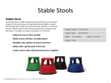
WORKSHOP STOOL
MODEL H6099
INSTRUCTION SHEET
COPYRIGHT © MAY, 2004 BY GRIZZLY INDUSTRIAL, INC.
WARNING: NO PORTION OF THIS MANUAL MAY BE REPRODUCED IN ANY SHAPE
OR FORM WITHOUT THE WRITTEN APPROVAL OF GRIZZLY INDUSTRIAL, INC.
#CA6262 PRINTED IN CHINA

PARTS INVENTORY
The Model H6099 was carefully packed when
it left our warehouse. If you discover the stool
is damaged after you have signed for delivery,
please call Customer Service immediately at
(570) 546-9663
for advice.
Save the containers and all packing materials for
possible inspection by the carrier or its agent.
Otherwise, filing a freight claim can be difficult.
When you are completely satisfied with the condi
-
tion of your shipment, you should inventory the
contents.
Figure 1 - Contents.
A. Stool Top .................................................... 1
B. Stool Pad .................................................... 1
C. Stool Legs .................................................. 4
D. Round Brace .............................................. 1
E. Bolt Bag ...................................................... 1
—M4 x 12 Tap Screws ...........................
8
—
M4-0.7 x 15 Phillips Head Screws .... 12
—M4-0.7 x 35 Phillips Head Screw ........
1
—M5-0.8 Lock Nuts ................................
4
—M5-0.8 x 45 Phillips Head Screws ......
4
—M4 Flat Washer ...................................
1
—Leg Holders .........................................
4
—Plastic Cross Joint ..............................
1
—Rubber Floor Guards ..........................
4
Figure 1. Model H6099 box contents.
A
B
C
D
E
Children may climb into plastic bags and
suffocate. Keep all plastic bags included in
packaging out of the reach of children.

Stool Assembly:
1. Slide a rubber floor guard onto the bottom
end of each stool leg.
2. Slide the top of each stool leg onto the plastic
cross joint and secure with the tap screws.
3. Place the round brace inside the stool legs
and attach using the M5-0.8 x 45 Phillips
head screws and lock nuts as shown in
Figure 2
.
ASSEMBLY INSTRUCTIONS
Figure 2. Correctly installed round brace.
4. Secure the stool pad to the stool top with four
M4-0.7 x 15 Phillips head screws.
5. Insert the M4-0.7 x 35 Phillips head screw
and flat washer through the plastic cross joint
and into the stool top.
6. Attach the assembled frame to the under-
side of the stool top and secure with the leg
holders and eight M4-0.7 x 15 Phillips head
screws as shown in
Figure 3.
Figure 3. Installed stool pad and legs.

1 PH6099001 STOOL PAD
2 PH6099002 STOOL TOP
3 PS21M PHLP HD SCR M4-.7 X 15
4 PH6099004 PLASTIC CROSS JOINT
5 PW05M FLAT WASHER 4MM
6 PS25M PHLP HD SCR M4-.7 X 35
7 PHTEK5M TAP SCREW M4 X 12
8 PH6099008 LEG HOLDER
9 PS87M PHLP HD SCR M5-.8 X 45
10 PLN02M LOCK NUT M5-.8
11 PH6099011 STOOL LEG
12 PH6099012 ROUND BRACE
13 PH6099013 RUBBER FLOOR GUARD
REF PART# DESCRIPTION
H6099 Parts Breakdown and List
-
 1
1
-
 2
2
-
 3
3
-
 4
4
Ask a question and I''ll find the answer in the document
Finding information in a document is now easier with AI
Related papers
-
Grizzly H8363 Owner's manual
-
Grizzly H8364 Owner's manual
-
Grizzly T10033 Owner's manual
-
Grizzly G1017 Owner's manual
-
Grizzly T1248 Owner's manual
-
Grizzly T1250 Owner's manual
-
Grizzly G0528 User manual
-
Grizzly Model G1022proz User manual
-
 Grizzly Industrial G1023RLWX Owner's manual
-
Grizzly G1023RL Owner's manual
Other documents
-
LumiSource BS-MASTER BKGY Assembly Instructions
-
LumiSource BS-ARC WL+W Assembly Instructions
-
 Xtend and Climb 963 Operating instructions
-
AmeriHome 800661 User manual
-
LumiSource BS-ECLAIR W Assembly Instructions
-
LumiSource BS-TW-MIRAGE BK Assembly Instructions
-
LumiSource BS-TW-MIRAGE SV Operating instructions
-
AmeriHome STL3TBX User manual
-
AmeriHome 804638 User manual
-
LumiSource BS-APEX BK+WL Assembly Instructions


