Miller KH18 Owner's manual

Category
Welding System
Type
Owner's manual

This manual is also suitable for

OWNER’S MANUAL
OM-844B 183 973B
April 1998
For RFCS-14 And RFCS-5 Foot Controls
READ SAFETY BLOCKS in welding power
source Owner’s Manual before proceeding.
WARNING
1. Typical Connection
Ref. ST-801 736
Turn Off welding power source.
1 Foot Control
2 Remote 14 Or Remote 5
Receptacle
Insert plug into matching 14-sock-
et, or 5-socket receptacle, as appli-
cable, on welding power source.
Tighten collar.
1
2
2. Remote Amperage Control For Welding Power Source Without
Remote Control Switch
Ref. ST-155 790-E
On
0 A DC
Off
Select Maximum
Amperage Percentage.
Select Weld Process Select Range And Polarity
33 A DC
Combination Front Panel
And
Remote Control
Approximately
50% = Approx. 33 A DC
Press pedal lightly to turn
weld output and gas flow
on. Press pedal further to
increase weld output.
Release pedal to turn off
weld output and gas flow.
OM-844 Page 2
3. Remote Amperage Control For Welding Power Source With Remote Control Switch
But Without Output (Contactor) Control
. See welding power source
Owner’s Manual to determine
if Remote Foot Control works
as a combination or as full
Amperage control.
Ref. ST-122 023-A / Ref. ST-141 127-A / ST-039 411-D
OR
EXAMPLE Of Full Remote Amperage Control
Set Switch
In Example:
Min = 30 A In Range A or 40 A In
Range B (Unit Minimum)
Max = 95 A In Range A or 200 A
In Range B (Control Setting)
Control Setting
Does Not Matter
Unit Maximum
In Example:
Min = 30 A In Range A or 40 A
In Range B (Unit Minimum)
Max = 225 A In Range A or 375 A
In Range B (Unit Maximum)
Unit Minimum
Unit Minimum
Control Setting
Set Desired Maximum
Amperage For Application
Set Switch
Press pedal to increase weld
output. Release pedal to
decrease weld output.
Press pedal to increase weld
output. Release pedal to
decrease weld output.
Example Of Combination Front Panel
And Remote Amperage Control
OM-844 Page 3
4. Remote Amperage Control For Welding Power Source With Remote Control Switch
And Output (Contactor) Control
. See welding power source
Owner’s Manual to determine
if Remote Foot Control works
as a combination or as full
Amperage control.
Ref. ST-114 018 / Ref. ST-801 736
0
On
Off
0
On
Off
EXAMPLE Of Full Remote Amperage Control
Control Setting
Does Not Matter
Set Switch Set Switch
Set Control
Set Switch Set Switch
Combination Front Panel
And
Remote Control
Control
Setting
(150 A)
Unit
Maximum
Press pedal lightly to turn weld
output and gas flow on. Press
pedal further to increase weld
output. Release pedal to turn
off weld output and gas flow.
Press pedal lightly to turn weld
output and gas flow on. Press
pedal further to increase weld
output. Release pedal to turn
off weld output and gas flow.
Example Of Combination Front Panel
And Remote Amperage Control
OM-844 Page 4
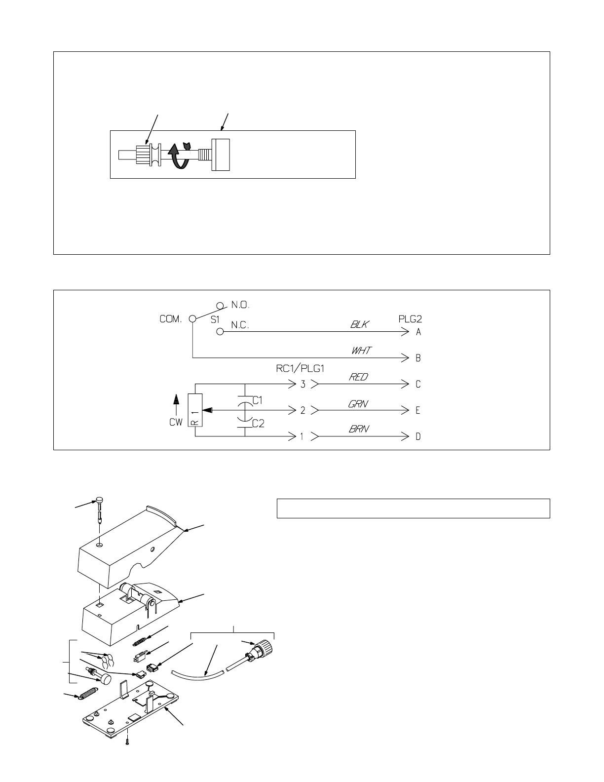
5. Adjusting Potentiometer Timing
Disconnect foot control from weld-
ing power source/generator.
Turn unit upside down, and remove
bottom plate.
1 Label
2 Gear
Turn gear on potentiometer shaft
counterclockwise as far as
possible.
Pull drive belt tight and mesh belt
teeth with gear teeth.
Connect free end of small spring
into end of drive belt.
Reinstall bottom plate
S-185 517
BEFORE RE-INSTALLING
BELT, TURN GEAR ALL
THE WAY TO THE STOP.
1
2
6. Circuit Diagram
SA-183 957-B
7. Parts List
ST-801 735
1
2
2
3
4 6
5
2
9
1
0
12
Part
No.
Item
No.
Qty
Description
1 190 092 Belt, drive 1 1. . . . . . . . . . . . . . . . . . . . . . . . . . . . . . . . . . . . . .
2 190 090 Pedal, foot 1 1. . . . . . . . . . . . . . . . . . . . . . . . . . . . . . . . . . . . .
3 182 627 Spring, ext .375 OD 1 1. . . . . . . . . . . . . . . . . . . . . . . . . . . . .
4 S1 183 629 Switch, limit 10A 125/250V 1 1. . . . . . . . . . . . . . . . . . .
5 182 628 Cable Control 1. . . . . . . . . . . . . . . . . . . . . . . . . . . . .
6 186 476 Cable Control 1. . . . . . . . . . . . . . . . . . . . . . . . . . . . . . . . . . . .
6 PLG1 131 204 Connector & Sockets 1 1. . . . . . . . . . . . . . . . . . . . .
7 175 284 Cable, port 20ga 5/c 21ft 21ft. . . . . . . . . . . . . . . . . . . . . . . . .
8 PLG2 144 310 Connector & Sockets 1. . . . . . . . . . . . . . . .
143 922 Connector, clamp str 1. . . . . . . . . . . . . . . . . . . . . . . . .
8 PLG2 039 273 Connector & Sockets 1. . . . . . . . . . . . . . . . . . . . . . .
039 685 Connector, clamp str 1. . . . . . . . . . . . . . . . . . . . . . . . . . . . . . . .
9 182 626 Spring, ext .750 OD 1 1. . . . . . . . . . . . . . . . . . . . . . . . . . . . .
10 R1 183 956 Potentiometer w/Leads 1k ohm 1 1. . . . . . . . . . . . . . .
11 RC1 131 203 Connector & Sockets 1 1. . . . . . . . . . . . . . . . . . . . .
12 C1,2 028 291 Capacitor, cer disc 2 2. . . . . . . . . . . . . . . . . . . . . . .
BE SURE TO PROVIDE MODEL AND STYLE NUMBER WHEN ORDERING
REPLACEMENT PARTS.
78
Dia.
Mkgs.
11
RFCS-14 RFCS-
5
1 / 1

Miller KH18 Owner's manual

Category
Welding System
Type
Owner's manual
This manual is also suitable for

Ask a question and I''ll find the answer in the document

Finding information in a document is now easier with AI

Ask the document