Page is loading ...

Page 1
38730-0-031838730-0-0318
GAS GRILL
CARE & USE / INSTALLATION

Page 2
38730-0-031838730-0-0318
Installation, Care And Use Of Your
BROILMASTER Professional Cooking Product
THIS MANUAL MUST REMAIN WITH THE PRODUCT OWNER FOR FUTURE REFERENCE.
This Manual Covers The Following
BROILMASTER Products:
GRILL BSG262N
MODELS BSG343N
BSG424N
FOR OUT DOOR USE ONLY
IMPROPER INSTALLATION, ADJUSTMENT, ALTERATION, SERVICE OR MAINTENANCE CAN
CAUSE PROPERTY DAMAGE, INJURY OR DEATH. READ THIS MANUAL THOROUGHLY
BEFORE INSTALLATION, USE OR SERVICING OF THIS EQUIPMENT
NOTE TO INSTALLER
This manual must remain with grill. Check your local building codes for proper method of
installation. In the absence of local codes, this unit should be installed in accordance with National
Fuel Gas Code No. ANSI Z21.58D-2002 USA or CAN/CGA-B149.1/.2 Natural Gas/Propane
Code. (Canada) latest edition or the National Electrical Code ANSI/NFPA No. 70 or the Canadian
Electrical Code CGA 1.6b2005 or latest edition.
*Grill Head Shown With Optional Carts Above

Page 3
38730-0-031838730-0-0318
TABLE OF CONTENTS
BROILMASTER BBQ Models..........................................................................................................2
Unique Features & Benets.............................................................................................................4
Product Specications .....................................................................................................................5
Overall Grill Dimensions ..................................................................................................................6
Control Identication ........................................................................................................................7
Warning Instructions ........................................................................................................................8
NOTICE: Commonwealth Of Massachusetts .................................................................................. 9
Grill Location..................................................................................................................................10
Location Of Your Grill (Using Your Grill During In Windy Conditions) ....................................... 11/12
Built-In Grill Dimensions ................................................................................................................ 13
Vent Registers ............................................................................................................................... 14
Built-In Sleeve Dimensions............................................................................................................15
Electrical Requirements & Hook-up...............................................................................................16
Wiring Schematics .........................................................................................................................17
LP Gas Cylinder Safety .................................................................................................................18
Gas Requirements & Hook-up........................................................................................19/20/21/22
Important Safety Grilling Information .............................................................................................23
Converting Your Gas Grill .........................................................................................................24/25
Converting Your Gas Grill Type ..................................................................................................... 26
Regulator Gas Conversion ............................................................................................................ 27
Lighting The Burners ..................................................................................................................... 28
Manually Lighting The Grill ............................................................................................................29
Burner Type Identication ..............................................................................................................30
Using The BROILMASTER Grill ....................................................................................................30
Direct Cooking Method ..................................................................................................................31
Indirect Cooking Method................................................................................................................31
Using The Rotisserie ..................................................................................................................... 32
Cooking Tips ..................................................................................................................................33
Burner Cleaning And Adjustment...................................................................................................34
Warnings .......................................................................................................................................35
Grill Cleaning Methods .................................................................................................................. 35
Cleaning The Grill .....................................................................................................................36/37
Light Bulb Replacement ................................................................................................................38
Warranty ........................................................................................................................................39
Master Parts Distributor List .......................................................................................................... 40
How To Order Repair Parts ...........................................................................................................40
Contacting Your BROILMASTER Dealer .......................................................................................41
BROILMASTER Parts List .............................................................................................................42
Parts Diagram............................................................................................................43/44/45/46/47
Sleeves, Side Burners, Covers And Island Accessories......................................................48/49/50

Page 4
38730-0-031838730-0-0318
4
BROILMASTER
Unique Features And Benets
The BROILMASTER gas grill has some of the most unique
grilling features that will enhance your grilling experience and
make you that “master chef”. These features include multilevel
grilling, enhanced ame tamers to create even heat and minimize
air-ups, Bow-tie burner design with multi ported heat zoning
technology and an optional infrared burner.
Far right grill
shown in the
lower position.
Multilevel cooking surfaces allow you to be able to cook
food closer to the burner and sear the food quickly while
raising the cooking surface allows more delicate food to be
cooked slower on the same heat. Food that may create more
areups can also be placed further away from the heat.
Years of design technology is placed into this “one of a kind”
vaporizer with Stainless Steel pyramid style avor bars and
specially designed evaporation plates. This ame tamer
pump’s even heat onto the food at the same time as vaporizing
overow juices that create added avor in the food.
Bow-tie burner technology is unique to BROILMASTER and
has been used for many years. This new Burner has “Zone
Porting” where the use of different size holes allows for even
heating for the front and back across the entire zone.
An optional sear burner takes the place of the traditional
Bow-tie burner for those occasions where intense heat is
required to quickly sear the food. Professional restaurants
have been using Infrared and sear technology to sear in the
natural juices of the food.

Page 5
38730-0-031838730-0-0318
Product Specications
Description
26" BSG262N 34" BSG343N 42" BSG423N
Main Cooking Area Dimension 456 608 760
Total Cooking Area Sq. In.
(Includes Warming Rack)
606 806 1006
Gas Type NAT NAT NAT
LP Conversion Kit Packed w/Grill Packed w/Grill Packed w/Grill
Orices Main Burners NAT Gas 2 - 2.08 mm 3 - 2.08 mm 4 - 2.08 mm
Orices Main Burners LP Gas 2 - 1.30 mm 3 - 1.30 mm 4 - 1.30 mm
Orices Rear Burner NAT Gas N/A 1.5 mm 1.5 mm
Orices Rear Burner LP Gas N/A 1.1 mm 1.1 mm
Burner Type
2 - Cast SS
Bow Tie
3 - Cast SS
Bow Tie
4 - Cast SS
Bow Tie
Burner BTU's (Each/Total) 18,000 / 36,000 18,000 / 54,000 18,000 / 72,000
Cooking Grids
2 - 5/16" Two
Position SS
3 - 5/16" Two
Position SS
4 - 5/16" Two
Position SS
Vaporizers - Flame Tamers
2 - SS
Pyramid Design
3 - SS
Pyramid Design
4 - SS
Pyramid Design
Heat Zone Dividers
1 - SS
(Removable)
2 - SS
(Removable)
3 - SS
(Removable)
Rear Rotisserie Burner N/A
11,000 BTU
Ceramic
11,000 BTU
Ceramic
Rotisserie Kit Optional Optional Optional
Lid Assembly
Fully Welded
w/Polished
Edges
Fully Welded
w/Polished
Edges
Fully Welded
w/Polished
Edges
Control Panel Fully Welded Fully Welded Fully Welded
Drip Tray Fully Welded Fully Welded Fully Welded
Ignition Type (No Battery)
Push And Turn
Flame Thrower
Push And Turn
Flame Thrower
Push And Turn
Flame Thrower
Warming Rack
SS Tilt And
Lock Away
SS Tilt And
Lock Away
SS Tilt And
Lock Away
Temp Gauge Hood Hood Hood
Control Panel Lights LED Blue 12V LED Blue 12V LED Blue 12V
Interior Work Lights 2 - Halogen 12V 2 - Halogen 12V 2 - Halogen 12V
Cutout Dimensions For Grill
11
3
/
4
H x
21D x 23
1
/
2
W
11
3
/
4
H x
21D x 31
1
/
2
W
11
3
/
4
H x
21D x 39
1
/
2
W
PRODUCT SPECIFICATIONS

Page 6
38730-0-031838730-0-0318
Overall Grill Dimensions
BSG262
BSG343
BSG424
SPECIFICATIONS
20-1/2"
20-1/2"
20-1/2"

Page 7
38730-0-031838730-0-0318
SPECIFICATIONS
Control Identication
BSG262
BSG343
BSG424

Page 8
38730-0-031838730-0-0318
• Read this manual carefully and completely before using your grill, to reduce the risk of
re, burn hazard or other injury, and to ensure proper installation and servicing.
• Never use rusted, dented or damaged propane cylinders. Never store additional or
empty propane cylinders in the grill cabinet or in the vicinity of this or any other gas or
electrical appliance. Do not store propane cylinders indoors or on their sides for gas
may escape. Gas cylinders are highly ammable.
• Any Children should never be left alone or unattended in an area where a grill is
located. Place your grill well away from areas where children play. Do not store items
that may interest children in or around the grill, in the cart, or in the enclosure or Island.
• Never move the grill when hot. When in use, portions of the grill are hot enough to
cause severe burns.
• Always maintain the required clearances from combustibles as detailed. The grill is
designed for outdoor use only. Never use in a garage, building, shed, breezeway, or
other enclosed area. Do not use this grill under any unprotected overhead combustible
construction. Combustible material exposed to heat will catch on re.
• Gas grills are not designed or certied for and are not to be installed in or on
recreational vehicles, portable trailers, boats or any other moving installation including
commercial use.
• Always have a Fire Extinguisher accessible — never attempt to extinguish a grease re
with water or other liquids.
• Store your grill in a well-ventilated area. If stored indoors, detach and leave L.P. cylinder
outdoors in a well-ventilated area away from heat and away from where children may
tamper with it. Always leave tank outdoors.
• Keep any electrical supply cord and the fuel supply hose away from any heated surfaces.
Electrical cords should be placed away from walkways to avoid tripping hazard.
• Do not repair or replace any part of the grill unless specically recommended in this manual.
Other service should be performed by a certied and qualied Gas and BBQ technician.
• If the grill is installed by a professional installer or technician, be sure that he/she shows
you where your gas supply shut-off is located. All gas lines must have a shut-off that is
readily and easily accessible. If you smell gas, check for gas leaks immediately. Check
only with a soap and water solution. Never check for gas leaks with an open ame.
• Inspect the L.P. gas supply hose prior to each use of the grill. If there is evidence of
excessive abrasion or wear, or the hose is cut, it must be replaced before using the grill.
• The outdoor cooking gas appliance and its individual shutoff valve must be
disconnected from the gas supply piping system during any pressure testing of that
system at test pressures in excess of 0.5 psi (3.5 kPa).
• The outdoor cooking gas appliance must be isolated from the gas supply piping system
by closing its individual manual shutoff valve during any pressure testing of the gas
supply piping system at test pressures equal to or less than 1/2 psi (3.5 kPa).
WARNING
! !
WARNING BEFORE USE

Page 9
38730-0-031838730-0-0318
NOTICE: Commonwealth Of Massachusetts
1. Massachusetts requires all gas be installed using a plumber or gas tter carrying the
appropriate Massachusetts license.
2. All permanently-installed natural gas or propane installations require a “T” handle type
manual gas valve be installed in the gas supply line to this appliance.
3. This does not apply to portable propane installations using a 20 pound cylinder.
WARNING! CALIFORNIA PROPOSITION 65
1. The burning of gas cooking fuel generates some by-products which are on the
list of substances which are known by the State of California to cause cancer or
reproductive harm.
2. California law requires businesses to warn customers of potential exposure to such
substances. To minimize exposure to the substances, always operate this unit
according to the use and care instructions found in this manual. Be certain to provide
adequate ventilation when cooking.
3. Warning: Handling the brass material on this product exposes you to lead, a chemical
known to the state of California to cause cancer, birth defects or other reproductive
harm. (Wash hands after handling this product.)
4. For more information go to this website: www.p65warning.ca.gov
!
WARNING BEFORE USE

Page 10
38730-0-031838730-0-0318
Grill Location
• Never install this product into a combustible enclosure without an insulated jacket.
Doing so could result in re, property damage and personal injury. Combustible
material is "anything" that can catch on re.
• Never locate the grill under a roof or overhang, in a building, garage, shed or other
such enclosed area.
• Installation must conform with local codes or, in the absence of local codes, with either
the National Fuel Gas Code, ANSI Z223.1/NFPA 54, Natural Gas and propane Installation
Code, CSA B149.1, or Propane Storage and Handling Code, B149.2, in Canada.
WHERE IS THE WIND COMING FROM?
When selecting a suitable location, consider
important factors such as exposure to the
wind and foot-trafc patterns.
If you have a free standing grill, position it
so the prevailing wind blows into the front
control panel (at your back when grilling),
supporting the proper front of BBQ to
rear of BBQ airow. Built-in grills located
in areas with prevailing winds should be
protected by a wind barrier.
Winds hitting the back of the grill directly
may cause problems, as well as wind
blowing along the hood opening
HOW LONG IS YOUR GAS RUN GOING
TO BE?
Keep all gas supply lines as short as
possible because gas lines lose pressure
over distance and with each elbow and tee
that is added. This drop in pressure affects
grill performance.
CHECK THE BBQ IS LEVEL?
Proper leveling during installation is critical.
A grill that is out of level will cause erratic
burner combustion and inefcient, uneven
heating. A carpenter’s spirit level should be
used to level the grill both front-to-back and
side-to-side.
If the oor is uneven or has a decided
slope, re-leveling may be required each
time you move a freestanding unit.
WARNING
! !
Be sure wind doesn’t blow into the back of the hood gap.
LOCATION OF YOUR GRILL

Page 11
38730-0-031838730-0-0318
LOCATION OF YOUR GRILL
Location Of Your Grill
USING YOUR GRILL IN WINDY
CONDITIONS:
• As a high-performance gas appliance,
your BROILMASTER grill requires
signicant amounts of air to support
the burner combustion process. Your
grill has been engineered to take air
in through the control panel area, and
exhaust the combustion out through the
gap between the front and rear hoods
• Using your grill in windy conditions can
disrupt the proper ow of air through your
grill, leading to reduced performance,
or in certain severe cases, causing heat
buildup in the control panel area. This
can lead to problems such as having
the control knobs getting hot or melting,
or burn hazards when the control panel
surfaces become too hot to touch.
• If you have a freestanding grill, it is best
to position the unit so the prevailing wind
blows into the front control panel (or at
your back), thus supporting the proper
airow. Winds hitting the back of the
grill directly are the most likely to cause
problems, although wind blowing along
the hood gap can also be a problem.
• Please note that damage to your grill
resulting from use in windy conditions,
such as melted knobs or igniter wires,
or control panel discoloration from heat
build-up, are excluded from warranty
coverage.
• Outdoor grilling can create more heat than
indoor kitchen ranges.
BUT THERE ARE A FEW THINGS
YOU CAN DO TO FURTHER PREVENT
THE POSSIBILITY OF IMPROPER
HEAT BUILDUP:
• If you suspect the grill is overheating,
using an heat resistant mitt, open the
front hood. Then adjust the burner
control knob to a lower setting. Do
not grab the knobs without testing the
temperature of them.
• Install your grill with a wind break
behind it. This is a wall, fence or
anything that will disrupt the wind
directly hitting the gas grill.
• Situate the grill so prevailing winds are
not blowing into the rear of the grill.
• On windy days, be careful not to
leave the hood down for more than 15
minutes when the burners are on high.
(Never leave the grill unattended when
in operation)
Wind hitting the back of the grill can disrupt proper exhaust.

Page 12
38730-0-031838730-0-0318
LOCATION OF YOUR GRILL
Location Of Your GRILL (Cont'd.)
• The grill drops into the cutout opening
and sits on the sides and back of the
grill. There is no need to fasten the grill
to the island. The gas grill must be able
to be removed for general maintenance
so do not grout sides or fasten in.
• For the hood to open there is a minimum
of 5" clearance behind the hood. There
is a required 12" clearance on each
side of the Gas Grill. Remember that
combustible materials should not be
located behind the grill, because the
5" space doesn't satisfy the distance
required from a combustible surface.
See below clearance to combustibles
.
CLEARANCE TO COMBUSTIBLE
CONSTRUCTION:
Minimum clearance from sides and back of
unit to adjacent combustible construction
below top of unit are 14" from sides and
16" from back. Use your grill at least 16"
away from any wall or surface.
Use your grill 16" or more away from
any combustible objects that can melt or
catch re such as vinyl or wood siding,
fences, overhangs, or any other sources
of ignition; including pilot lights and live
electrical appliances.
Do not use your grill under any overhead
combustible construction. Never use
your gas grill in a garage, porch, shed,
breezeway, or any other enclosed area.
Never use your gas grill on a balcony,
deck, or patio above the ground oor of
your home.
Installing this product into a combustible
enclosure without an insulated jacket could result
in re, property damage and personal injury.
WARNING
! !
BUILT IN LOCATION:
• The BROILMASTER Built in model is
designed for easy installation into a
non-combustible masonry enclosure.
• The BBQ must be surrounded by
non-combustible material like Brick
or Hardibacker but should never be
installed into a wood island without
a insulated sleeve (accessory)
surrounding the Gas Grill.
5"
Hood Clearance
14"
Distance Minimum
16"
16"
Combustible
Materials

Page 13
38730-0-031838730-0-0318
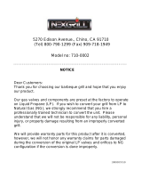
CUT OUT DIMENSIONS
Built In Grill Dimensions
Model # Cutout A Cutout B Cutout C
26" 2 Burner
BSG262N 11 3/4 21 23 1/2
34" 3 Burner
BSG343N 11 3/4 21 31 1/2
42" 4 Burner
BSG424N 11 3/4 21 39 1/2
BSG262 BSG343 BSG424
22
1
/
2
"
11
1
/
4
"
26"
34"
42"
39"
31"
23"
BACK OF BBQ
BACK OF BBQBACK OF BBQ
1
1
/
2
"
1
1
/
2
" 1
1
/
2
" 1
1
/
2
"
1
1
/
2
"1
1
/
2
"
Cutout
detail when
countertop
is overhung

Page 14
38730-0-031838730-0-0318
Vent Registers
LP Gas
INSULATED SLEEVE INSTALLATION INSTRUCTIONS
IMPORTANT: Before you build the frame, you must take into consideration the total weight
of the sleeve, grill and any nishing materials.
Review the table on the next page for the
proper framing dimensions for the insulation
sleeve. Determine the entry point for both
the gas inlet and electric connections. Make
the 4” square holes for gas and electrical
connections (rear or bottom access) based
on your requirements. Note that the gas and
electrical connections are located on the
right side.
A “Level” should be used to assure that
the framing is level, both front to back and
side to side.
NOTE: Never under any circumstance
should you install the transformer or run
a gas hose in between the grill and the
inside of the insulating sleeve.
SLEEVE INSTALLATION
Position the sleeve into the frame. No part
of the combustible enclosure can protrude
above the top surface or in front of the face
surface of the liner.
GRILL INSTALLATION
Use the proper equipment to support the
grill. Place the grill into the sleeve and place
it over the sleeve lip across the back and
sides. The liner is designed to support the
grill without additional fasteners.
FINISHING
If desired any gap remaining between the
sleeve and the combustible enclosure may
be lled with a non-combustible sealant.
INSULATED SLEEVE
REQUIRED WHEN AN LP
GAS TANK IS USED
10 Square Inch Minimum
Each Register. 2 Per
Side. 1 High And 1 Low
2 1/4"
Minimum
Ground To
Vent Bottom

Page 15
38730-0-031838730-0-0318
WARNING BEFORE USE
FOR COMBUSTIBLE INSTALLATIONS
Built-In Sleeve Dimensions
Model # Cutout A Cutout B Cutout C Cutout D Cutout E Cutout F
26" 2 Burner
BSG262 12 3/4 22 3/4 25 3/4 2 1/4 2 1/4 2 1/4
34" 3 Burner
BSG343 12 3/4 22 3/4 33 3/4 2 1/4 2 1/4 2 1/4
42" 4 Burner
BSG424 12 3/4 22 3/4 41 3/4 2 1/4 2 1/4 2 1/4
4" square hole for
gas and electrical
connections, rear
or bottom.
Cutout
detail when
countertop
is overhung
1"

Page 16
38730-0-031838730-0-0318
ELECTRICAL REQUIREMENTS
Electrical Requirements And Hook-up
WARNING! ELECTRICAL GROUNDING
• Product installation must meet local electric codes or, in the absence of local codes, the
latest edition of the National Electrical Code ANSI/NFPA No. 70 or the Canadian Electrical
Code CGA 1.6b2005.
• Use only a Ground Fault Interrupter (GFI) protected circuit with this outdoor cooking
gas appliance.
• This grill is equipped with a three prong (grounding) electric plug for your protection against
shock hazard and must be plugged directly into a properly grounded three prong outlet.
Never cut or remove the grounding prong from this plug.
• Use only extension cords with a 3 prong grounding plug, rated for the power of the
equipment, and approved for outdoor use with a “W-A” marking.
• To protect against electric shock, do not immerse any part of the power cord, an extension
cord or any plugs in water or other liquid.
• Unplug the product from the outlet when not in use and before cleaning. Allow it to cool
before putting on or taking off parts.
• Do not let the cord touch hot surfaces.
• Do not use an outdoor cooking gas appliance for purposes other than intended.
• Do not operate any outdoor cooking gas appliance with a damaged cord, plug, or after the
appliance malfunctions or has been damaged in any manner. Contact the dealer for repair.
To protect against shock hazard risk, connect
only to properly Grounded Outlet.
CAUTION
! !
CALIFORNIA PROPOSITION 65
The electrical supply cord and plug of the
Rotisserie and Transformer contain chemicals,
including lead, known to the State of California
to cause cancer, and birth defects or other
reproductive harm. Wash hands after handling.
WARNING
! !
This appliance, when installed, must be electrically
grounded in accordance with local codes or, in the
absence of local codes, with the National Electrical
Code, ANSI/NFPA 70, or the Canadian Electrical
Code, CSA C22.1. Keep any electrical supply cord and
the fuel supply hose away from any heated surface.
WARNING
! !
!

Page 17
38730-0-031838730-0-0318
ELECTRICAL REQUIREMENTS
Wiring Schematics
NOTE: This grill uses a transformer to provide power to the LED lights and work lights.
The transformer should be secured to the island walls or cart back wall. Plug only into a
Ground Fault Interrupter (GFI) protected circuit.

Page 18
38730-0-031838730-0-0318
LP Gas grill models are designed for use
with a standard 20lb. Liquid Propane Gas
(LP Gas) tank (sold separately. Never
connect your gas grill to an LP Gas tank
that exceeds this capacity. A tank of
approximately 12 inches in diameter by
18-1/2 inches high is the maximum size
LP Gas tank to use. You must use an
"OPD" gas tank which has a listed Overll
Prevention Device. This safety feature
prevents tank from being overlled which
can cause a malfunction of the LP Gas tank.
The LP Gas tank must be constructed
and marked in accordance with the
Specications for LP-Gas Cylinders of the
U.S. Department of Transportation (D.O.T.
or the National Standard of Canada, CAN/
CSA-B339, Cylinders, Spheres and Tubes
for Transportation of Dangerous Goods,
and Commission; as applicable.
The LP Gas tank must have a shutoff valve,
terminating in an LP Gas supply tank valve
outlet, that is compatible with a Type 1 tank
connection device. The LP Gas tank must
also have a safety relief device that has a
direct connection with the vapor space of
the tank. The tank supply system must be
arranged for vapor withdrawal.
The LP Gas tank must have a collar to
protect the tank valve. Never connect an
unregulated LP gas tank to your gas grill.
The gas regulator assembly supplied with
your gas grill is adjusted to have an outlet
pressure of 11" water column (W.C.) for
connection to an LP gas tank. Only use the
regulator and hose assembly supplied with
your gas grill.
Replacement hose and regulator assembly
must be identical to those listed in the parts
list of this Operator's Manual as specied
by BROILMASTER.
Have your LP Gas dealer check the release
valve after every lling to ensure it remains
free of defects. Always keep LP Gas tank in
upright position. Do not subject the LP Gas
tank to excessive heat.
Never store an LP Gas tank indoors. If you
store your gas grill in the garage always
disconnect the LP Gas tank rst and store it
safely outside.
LP Gas tanks must be stored outdoors in a
well-ventilated area and out of the reach of
children. Disconnected LP Gas tanks must
not be stored in a building, garage or any
other enclosed area.
The regulator and hose assembly can be
seen by opening the cart or island doors.
They must be inspected before each use of
the grill. If the hose is damaged in any way, it
must be replaced prior to using the grill again.
The Gas Grill is setup to operate with a
LP Gas Cylinder equipped with an OPD
(Overlling Prevention Device).
LP Gas Cylinder Safety
Do not store a spare LP-Gas tank under or near
this appliance. Never ll the tank beyond 80
percent full; and if the information is not followed
exactly, a re causing death or serious injury
may occur.
WARNING
! !
LP GAS SAFETY

Page 19
38730-0-031838730-0-0318
GAS REQUIREMENTS
Type 1 connection
per ANSI Z21.58b-2012/CSA
1.6b-2012
Quick
Coupling
Nut
Gas Requirements And Hook-up
LP GAS MODEL ONLY - TYPE 1
CONNECTION WITH REGULATOR
AND HOSE TO YOUR LP GAS TANK.
Connect and tighten the swivel nut of the
gas hose to the grill manifold shown below.
Turn all Control Knobs to the OFF
position. Inspect the valve connection
port and regulator assembly for damage
or debris. Remove any debris. Never use
damaged equipment.
Connect the regulator assembly to the tank
valve and HAND TIGHTEN nut clockwise to
a full stop. DO NOT use a wrench to tighten
because it could damage the Quick Coupling
Nut and result in a gas leak/re hazard.
Open the tank valve a full turn
(counterclockwise) and use a soapy water
solution to check all connections for leaks
before attempting to light your grill. See
"Check All Connections for LP Gas Leaks." If
a leak is found, turn the tank valve off and do
not use your grill until the leak is repaired.
CHECK ALL CONNECTIONS
FOR LP GAS LEAKS.
Never test for leaks with an open ame.
Prior to rst use, at the beginning of each
season, or every time your LP Gas tank is
changed, you must check for gas leaks.
FOLLOW THESE THREE STEPS:
1. Make a soap solution by mixing one part
liquid detergent and one part water.
2. Turn the grill Control Knobs to the full OFF
position, then turn the gas ON at source.
3. Apply the soap solution to all gas
connections. If bubbles appear in the
soap solution the connections are not
properly sealed. Check each tting and
tighten or repair as necessary.
LP Gas Tank
Regulator
with Hose
(LPG)
Gas Valve/
Manifold
Assembly
NOTE: No Appliance
Regulator Is Used When
An LP Tank And Type 1
Connector And Regulator
Are Used.

Page 20
38730-0-031838730-0-0318
GAS REQUIREMENTS
CAUTION: When the appliance is not in use
the gas must be turned off at the tank. Place
dust cap on cylinder valve outlet whenever
the cylinder is not in use. Only install the type
of dust cap on the cylinder valve outlet that
is provided with the cylinder valve. Other
types of caps or plugs may result in leakage
of propane.
DISCONNECTING A LIQUID PROPANE
GAS (LPG) TANK FROM YOUR GRILL
1. Make sure the Burner Valves and LP
Gas tank valve are off. (Turn clockwise
to close.)
2. Detach the hose and regulator
assembly from the LP Gas tank valve
by turning the Quick Coupling Nut
counterclockwise.
3. Do not use a wrench or any tools when
turning the Quick Coupling Nut.
Gas Requirements And Hook-up (Cont'd.)
Failure to read and follow the Use and Care
Instructions could result in a re or explosion
that could cause serious bodily injury, death, or
property damage.
WARNING
! !
If you have a gas leak that cannot be repaired,
turn off the gas at the source and disconnect the
fuel line from your grill. Call your gas supplier or
re department for repair assistance.
WARNING
! !
1. Do not store spare LP cylinder within 10 feet
(3m) of this appliance.
2. Do not store or use gasoline or other
ammable liquids and vapors within 25 feet
(8m) of this appliance.
3. When cooking with oil/grease, do not allow
the oil/grease to get hotter 350°F (177°C).
4. Do not leave oil/grease unattended.
WARNING
! !
/