Page is loading ...

LDLINE
CONTROLS INC.
G
www.goldlinecontrols.com
888-921-7665
Aqua LogicAqua Logic
Aqua LogicAqua Logic
Aqua Logic
Automation and Chlorination
Installation Manual
for models
AQ-LOGIC-PS-4
AQ-LOGIC-PS-8

IMPORTANT SAFETY INSTRUCTIONS
When using this electrical equipment, basic safety precautions should always be
followed, including the following:
•
READ AND FOLLOW ALL INSTRUCTIONS
•
!
WARNING: Disconnect all AC power during installation.
•
!
WARNING: Water in excess of 100 degrees Fahrenheit may be
hazardous to your health.
•
!
WARNING: To reduce the risk of injury, do not permit children to
use this product unless they are closely supervised at all times.
• A green colored terminal marked “Earth Ground” is located inside the wiring
compartment. To reduce the risk of electric shock, this terminal must be
connected to the grounding means provided in the electric supply service
panel with a continuous copper wire equivalent in size to the circuit conductors
supplying the equipment.
• One bonding lug for US models (two for Canadian models) is provided on the
external surface. To reduce the risk of electric shock, connect the local
common bonding grid in the area of the swimming pool, spa, or hot tub to
these terminals with an insulated or bare copper conductor not smaller than 8
AWG US / 6 AWG Canada.
• All field installed metal components such as rails, ladders, drains, or other
similar hardware within 3 meters of the pool, spa or hot tub shall be bonded to
the equipment grounding bus with copper conductors not smaller than 8 AWG
US / 6 AWG Canada.
• SAVE THESE INSTRUCTIONS

Table of Contents
Introduction Before You Begin................................................................... 1
Plumbing Requirements....................................................... 2
Electrical Requirements....................................................... 2
Installation Steps.................................................................... 2
1. Preparing General Water Chemistry..................................................... 3
Pool/Spa Water Salt.......................................................................................... 4
2. Mounting Aqua Logic Control Center................................................... 6
Equipment Temperature Sensors........................................................... 6
Optional Wired Remote Display/Keypad........................... 6
Optional Wireless Remote Display/Keypad....................... 7
Optional Base Receiver........................................................ 7
Valve Actuators...................................................................... 7
3. Plumbing General Equipment............................................................... 8
Turbo Cell............................................................................... 9
Flow Switch............................................................................ 9
4. Electrical Main Service.......................................................................... 10
Wiring Grounding and Bonding........................................................ 11
Circuit Breaker Installation and Wiring......................... ...... 11
General Purpose Outlet........................................................ 11
Aqua Logic Control Power................................................... 11
High Voltage Pool Equipment.............................................. 12
Low Voltage Wiring............................................................... 13
5. Configuration Configuration Menu.............................................................. 19
6. System Startup Before Startup........................................................................ 26
and Checkout Heater Checkout................................................................... 26
Service Mode........................................................................ 27
7. Warranty Aqua Logic Limited Warranty.............................................. 28

Introduction
Before You Begin
Before installing the Aqua Logic System
-Determine that you have everything necessary to complete the installation
-Find a suitable mounting location for both the control center and remote keypad
-Plan and determine where components will be plumbed
-Plan wire runs and wiring connections
What’s Included
Before attempting to install the Aqua Logic system, check that the following components have been in-
cluded in the package:
Aqua Logic Electronics Unit
(2) Temperature sensors with 12 ft. (4m) cable, hose clamp
TurboCell kit
(1) Turbo Cell with 12ft. (4m) cable with unions
(1) Flow switch with 12ft. (4m) cable
What’s NOT Included
Some of the additional items that you may need to complete an installation include:
Circuit breakers
None are included with control—see page 11 and inside of door for suitable breakers
Wire
4-conductor cable (electronics unit to remote display/keypad)
Wire/conduit for 100A service from main panel to Aqua Logic
Wire/conduit for filter pump and other high voltage loads
Wire for bonding
Miscellaneous
Utility electrical outlet and weatherproof cover (for mounting on side of Aqua Logic)
Mounting hardware (screws, etc.) for mounting Aqua Logic and remote display/keypad
Valves (use standard Jandy, Pentair/Compool, or Hayward valves)
Valve, actuator, and solar sensor for solar control option. Additional cable for the solar sensor may also
be required
Accessory Products - Order Separately
AQL-REMOTE-PS-4 Wired Remote Display (see note 1)
AQL-REMOTE-PS-8 Wired Remote Display (see note 2)
AQL-REMOTE-RF-PS-4 Wireless Remote Display (see notes 1, 3,4)
AQL-REMOTE-RF-PS-8 Wireless Remote Display (see notes 2, 3,4)
AQL-SPASIDE-RF Wireless Spaside Remote Control (see note 3)
AQL-BASE-RF Base Receiver
GVA-24 Valve Actuator
AQ-SOL-KIT-xx Solar Kit (xx=1P (1.5” pos. seal), -2P (2” pos. seal), -2NP (2” non-pos. seal)
V&A-xx Valve & Actuator (xx=1P (1.5” pos. seal), -2P (2” pos. seal), -2NP (2” non-pos. seal)
notes: 1. for use with Aqua Logic PS-4 model only
2. for use with Aqua Logic PS-8 model only
3. requires base receiver AQL-BASE-RF
4. 9V wall power supply included
1

Plumbing Requirements
The only special plumbing requirements for the Aqua Logic are the Turbo Cell and flow switch which are
typically plumbed after the heater but before the pool/spa return valve. Refer to page 9 for detailed
instructions.
Electrical Requirements
Power must be shut off at the circuit breaker before performing any wiring. Be sure to follow all local and
NEC electrical codes.
The Aqua Logic is designed to be used as a circuit breaker subpanel for all the pool equipment. Run the
electrical service from the house’s main panel to the Aqua Logic, then install the appropriate circuit breakers
and wire the pool equipment through the Aqua Logic relays. If desired, an external subpanel can be used.
The Aqua Logic control circuit requires 120VAC power. A utility receptacle (not included) can be mounted
in the side of the Aqua Logic box to provide 120VAC power if desired.
Installation Steps
Details on each installation step are presented on the following pages:
1. Prepare the pool water (page 3)
General Water Chemistry
Salt
2. Mounting the equipment (page 6)
Aqua Logic main unit
Remote display/keypad (optional)
Temperature sensors
Valve actuators (if applicable)
3. Plumbing (page 8)
General Pool Equipment
Turbo Cell
Flow Switch
4. Electrical Wiring (page 10)
Main service
Grounding and bonding
Circuit breakers
Aqua Logic control power
High Voltage pool equipment
Low voltage wiring (temperature sensors, flow switch, etc.)
5. Aqua Logic control configuration (program desired control operation) (page 19)
6. System Startup and checkout (page 26)
2

ºC ºF
Ti
Calcuim
Hardness
Ci
Total
Alkalinity
Ai
53
60
66
76
84
94
103
12
16
19
24
29
34
39
.3
.4
.5
.6
.7
.8
.9
How to use: Measure pool pH, temperature, calcium hardness,
and total alkalinity. Use the chart above to determine Ti, Ci,and
Ai from your measurements. Insert values of pH, Ti, Ci and Ai
into the above equation. If Si equals .2 or more, scaling and
staining may occur. If Si equals -.2 or less corrosion or irritation
may occur.
Si = pH + Ti + Ci + Ai - 12.
1
-.2
0.2
CORROSIVE SCALING
75 75
100 100
125 125
150 150
200 200
250 250
300 300
400 400
600 600
800 800
1.5 1.9
1.6 2.0
1.7 2.1
1.8 2.2
1.9 2.3
2.0 2.4
2.1 2.5
2.2 2.6
2.4 2.8
2.5 2.9
OK
1. Preparing Pool/Spa Water
General Water Chemistry
Salt is required only if you are using the chlorinator features on the Aqua Logic Control. If you are NOT
using the chlorinator, it is recommended that you follow all of the other chemistry recommendations be-
sides salt. Refer to the description of the Aqua Logic configuration menu for information on enabling/
disabling the chlorinator (see pg 19).
Water Chemistry
The table below summarizes the levels that are recommended by the National Spa and Pool Institute
(NSPI). The only special requirements for the Aqua Logic are the salt level and stabilizer.
Saturation index
The saturation index (Si) relates to the calcium and alkalinity in the water and is an indicator of the pool
water “balance”. Your water is properly balanced if the Si is 0 ±0.2. If the Si is below -0.2, the water is
corrosive and plaster pool walls will be dissolved into the water. If the Si is above +0.2, scaling and
staining will occur. Use the chart below to determine the saturation index.
3

The pool’s chemistry must be balanced BEFORE activating the Aqua Logic’s sanitizing function. NOTE:
If the pool does not have new water, add metal remover and non-copper based algaecide to the pool, per
manufacturer’s instructions. This ensures a quick, troublefree transfer to the Aqua Logic system.
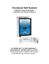
Salt
Salt Level
Use the chart below to determine how much salt in pounds or (Kgs) should be added to reach the recom-
mended levels. Use the equations on the following page (measurements are in feet/gallons and meters/
liters) if pool size is unknown.
The operating salt level is between 2700-3400 PPM (parts per million) with 3200 PPM being optimal.
Before adding any salt, test the salt level. This is especially important for retrofit installation to older pools
where all of the chlorine added to the pool over time is ending up as salt. If the level is low, determine the
number of gallons in the pool and add salt according to the chart below. A low salt level will reduce the
efficiency of the sanitization and result in low chlorine production. A high salt level can cause the Aqua
Logic to stop chlorinating. The salt in your pool/spa is constantly recycled and the loss of salt throughout
the swimming season should be minimal. This loss is due primarily to the addition of water because of
splashing, backwashing, or draining (because of rain). Salt is not lost due to evaporation.
Gall
o
n
s
a
n
d
(
L
i
t
e
r
s
)
o
f
P
o
o
l
/
S
p
a
w
a
t
e
r
12,000 14,000 16,000
1
8
,
0
0
0
2
0
,
0
0
0
2
2
,
0
0
0
3
2
,
0
0
0
2
4
,
0
0
0
3
4
,
0
0
0
2
6
,
0
0
0
3
6
,
0
0
0
2
8
,
0
0
0
3
8
,
0
0
0
3
0
,
0
0
0
4
0
,
0
0
0
Current salt
level
(45000) (52,500) (60,000)
(
6
7
,
5
0
0
)
(
7
5
,
0
0
0
)
(
8
2
,
5
0
0
)
(
1
2
0
,
0
0
0
)
(
9
0
,
0
0
0
)
(
1
2
7
,
5
0
0
)
(
9
7
,
5
0
0
)
(
1
3
5
,
0
0
0
)
(
1
0
5
,
0
0
0
)
(
1
4
2
,
5
0
0
)
(
1
1
2
,
5
0
0
)
(
1
5
0
,
0
0
0
)
ppm
0
320
(145)
373
(170)
427
(194)
4
8
0
(
2
1
8
)
(242)
587 854
(267) (388)
640 907
(291) (412)
693 960
(315) (436)
747
(339) (4
6
0
)
800
1
0
6
7
(364)
(
4
8
4
)
200
300
(136)
350
(159)
400
(182)
450
(205)
500
(227)
550 800
(250)
(363)
600 850
(273) (385)
650 900
(295) (408)
700 9
5
0
(318) (4
3
0
)
750
1
0
0
0
(341)
(
4
5
3
)
400
280
(127)
327
(148)
373
(170)
420
(191)
467
(212)
513 747
(233) (339)
560 793
(255) (360)
607 840
(276) (382)
653 8
8
7
(297) (4
0
3
)
700
9
3
3
(318)
(
4
2
4
)
600
260
(118)
303
(138)
347
(158)
390
(177)
433
(197)
477 693
(217) (317)
520 737
(236) (337)
563 780
(256) (358)
607 8
2
3
(276) (3
7
8
)
650
8
6
7
(297)
(
3
9
8
)
800
240
(109)
280
(127)
320
(145)
360
(164)
400
(182)
440 640
(200) (291)
480 680
(218)
(310)
520 720
(236) (328)
560 76
0
(255) (3
4
6
)
600
8
0
0
(273)
(
3
6
4
)
1000
220
(100)
257
(117)
293
(133)
330
(150)
367
(167)
403 587
(183) (267)
440 623
(200) (283)
477 660
(217) (300)
513 69
7
(233) (3
1
7
)
550
7
3
3
(250)
(
3
3
3
)
1200
200
(91)
233
(106)
267
(121)
300
(136)
333
(152)
367 533
(167) (243)
400 567
(182) (258)
433 600
(197) (274)
467 63
3
(212) (2
8
9
)
500
6
6
7
(227)
(
3
0
4
)
1400
180
(82)
210
(95)
240
(109)
270
(123)
300
(136)
330 480
(150) (218)
360 510
(164) (232)
390 540
(177) (246)
420 57
0
(191) (2
5
9
)
450
6
0
0
(205)
(
2
6
3
)
1600
160
(73)
187
(85)
213
(97)
240
(109)
267
(121)
293 427
(133)
(195)
320 453
(145) (207)
347 480
(158) (219)
373 50
7
(170) (2
3
1
)
400
5
3
3
(182)
(
2
4
3
)
1800
140
(64)
163
(74)
187
(85)
210
(95)
233
(106)
257 373
(117) (169)
280 397
(127) (180)
303 420
(138) (190)
327 44
3
(148) (20
1
)
350
4
6
7
(159)
(
2
1
1
)
2000
120
100
80
60
20
40
(55)
(45)
(36)
(27)
(9)
(18)
140
117
23
47
(64)
(53)
(11)
(21)
160
133
27
53
(73)
(61)
(12)
(24)
180
150
30
60
(82)
(68)
(14)
(27)
200
167
33
67
(91)
(76)
(15)
(30)
220 320
183 267
37 53
73 107
(100) (145)
(83) (121)
(17) (24)
(33) (48)
240
340
200 283
40
57
80 113
(109) (154)
(91) (129)
(18) (26)
(36) (51)
260 360
217 300
43 60
87 120
(118) (163)
(98) (137)
(20) (27)
(39) (54)
280 38
0
233 31
7
47
6
3
93
1
2
7
(127) (17
2
)
(106) (1
4
4
)
(21) (2
9
)
(42) (5
7
)
300
4
0
0
250
3
3
3
50
6
7
100
1
3
3
(136)
(
1
8
1
)
(114)
(
1
5
2
)
(23)
(
3
0
)
(45)
(
6
0
)
(32)
80
(36)
90
(41)
100
(45)
1
1
0
1
6
0
(
5
0
)
(
7
3
)
1
2
0
1
7
0
(
5
5
)
(
7
7
)
1
3
0
1
8
0
(
5
9
)
(
8
1
)
1
4
0
1
9
0
(
6
4
)
(
8
6
)
1
5
0
2
0
0
(
6
8
)
(
9
0
)
93
(42)
107
(48)
120
(55)
133
(61)
1
4
7
2
1
3
(
6
7
)
(
9
8
)
1
6
0
2
2
7
(
7
3
)
(
1
0
4
)
1
7
3
2
4
0
(
7
9
)
(
1
1
0
)
1
8
7
2
5
3
(
8
5
)
(
1
1
7
)
2
0
0
2
6
7
(
9
1
)
(
1
2
3
)
2200
3000
2800
2400
3200
Ideal Ideal Ideal Ideal Ideal
I
d
e
a
l
I
d
e
a
l
I
d
e
a
l
I
d
e
a
l
I
d
e
a
l
I
d
e
a
l
I
d
e
a
l
I
d
e
a
l
I
d
e
a
l
I
d
e
a
l
2600
3400
OK
OK
OK
OK
OK OK OK
O
K
O
K
O
K
O
K
O
K
O
K
O
K
O
K
O
K
O
K
P
O
U
N
D
S
a
n
d
(
K
g
)
O
F
S
A
L
T
N
E
E
D
E
D
F
O
R
3
2
0
0
P
P
M
3600+
Dilute Dilute Dilu
t
e
D
i
l
u
t
e
D
i
l
u
t
e
D
i
l
u
t
e
D
i
l
u
t
e
D
i
l
u
t
e
D
i
l
u
t
e
D
i
l
u
t
e
D
i
l
u
t
e
D
i
l
u
t
e
D
i
l
u
t
e
D
i
l
u
t
e
D
i
l
u
t
e
10,000
8,000
(37,500)
213
267
(97)
(121)
200 250
(91) (114)
187 233
(85)
(106)
173
217
(79)
(98)
160 200
(73)
(91)
147 183
(67) (83)
133 167
(61) (76)
120 150
(55) (68)
107 133
(48) (61)
93 117
(42) (53)
80 100
67 83
53
67
40 50
13 17
27 33
(36) (45)
(30) (38)
(24) (30)
(18) (23)
(6) (8)
(12)
(15)
Ideal
Ideal
Dilute
Dilute
(30,000)
4

Pool Sizing Formula
Type of Salt to Use
It is important to use only sodium chloride (NaCl) salt that is greater than 99% pure. This is common food
quality or water softener salt and is usually available at building supply stores in 40-80 lb. bags labeled
coarse or fine “Solar Salt”. It is also acceptable to use water conditioning salt pellets, however, it will take
longer for them to dissolve. Do not use rock salt, or salt with more than 1% of yellow prussiate of soda,
salt with anti-caking additives, or iodized salt.
How to Add Salt
For new plaster pools, wait 10-14 days before adding salt to allow the plaster to cure. Turn the circulating
pump on and add salt directly into the pool. Brush the salt around to speed up the dissolving process—do
not allow salt to pile up on the bottom of the pool. Run the filter pump for 24 hours with the suction coming
from the main drain (use pool vacuum if there is no main drain) to allow the salt to evenly disperse through-
out the pool. The salt display may take 24 hours to respond to the change in salt concentration.
Always check stabilizer (cyanuric acid), when checking salt. These levels will most likely decline together.
Use the chart below to determine how much stabilizer must be added to raise the level to 80 ppm.
Gallons
Liters
(pool size in feet)
(pool size in meters)
Rectangular
Round
Oval
Diameter x Diameter x
Average Depth x 5.9
Length x Width x
Average Depth x 6.7
Length x Width x
Average Depth x 7.5
Diameter x Diameter x
Average Depth x 785
Length x Width x
Average Depth x 893
Length x Width x
Average Depth x 1000
POUNDS and (Kg) OF STABILIZER (CYANURIC ACID) NEEDED FOR 80 PPM
Gallons and (Liters) of Pool/Spa water
Current
Stabilizer
Level (ppm)
0 ppm
20 ppm
60 ppm
30 ppm
40 ppm
50 ppm
70 ppm
80 ppm
10 ppm
12,000
(45000)
8,000
(30000)
14,000
(52500)
10,000
(37500)
16,000
(60000)
18,000
(67500)
20,000
(75000)
22,000
(82500)
32,000
(120000)
24,000
(90000)
34,000
(127500)
26,000
(97500)
36,000
(135000)
28,000
(105000)
38,000
(142500)
30,000
(112500)
40,000
(150000)
8.0
(3.6)
5.3
(3.6)
8.0
(3.6)
8.0
(3.6)
9.4
(4.3)
6.7
(4.3)
9.4
(4.3)
10.7
(4.9)
12.0
(5.4)
12.0
(5.4)
13.4
(6.1)
14.7
(6.7)
21.3
(9.7)
16.0
(7.3)
22.7
(10.3)
18.7
(8.5)
25.3
(11.5)
20.0
(9.1)
26.7
(12.0)
7.0
)
(3.2
4.7
(3.2)
8.2
(3.7)
5.8
(3.7)
10.5
(4.8)
11.7
(5.3)
12.9
(5.9)
18.7
(8.5)
14.0
(6.4)
19.8
(9.0)
15.2
(6.9)
21.0
(9.5)
16.4
(7.4)
22.2
(10.0)
17.2
(8.0)
23.3
(10.5)
6.0
(2.7)
4.0
(2.7)
6.0
(2.7)
6.0
(2.7)
8.5
(3.9)
7.0
(3.2)
9.0
(2.2)
10.0
(4.5)
10.0
(4.5)
14.2
(6.3)
11.0
(5.0)
16.0
(7.2)
13.0
(5.9)
18.0
(8.1)
14.0
(6.4)
19.0
(8.6)
15.0
(6.8)
20.0
(9.0)
5.0
(2.3)
3.3
(2.3)
5.0
(2.3)
5.9
(2.7)
4.2
(2.7)
6.7
(3.0)
8.4
(3.8)
6.7
(3.0)
7.5
(3.4)
9.2
(4.2)
13.3
(6.0)
10.8
(4.9)
15.0
(6.7)
11.7
(5.2)
15.8
(7.1)
12.5
(5.6)
16.7
(7.5)
4.0
(1.8)
2.7
(1.8)
4.0
(1.8)
4.0
(1.8)
5.7
(2.6)
4.7
(2.1)
3.3
(2.1)
5.4
(2.4)
7.4
(3.3)
10.7
(4.8)
8.7
(3.9)
12.0
(5.4)
9.3
(4.2)
12.7
(5.7)
10.0
(4.5)
13.3
(6.0)
3.0
(1.4)
2.0
(1.4)
3.0
(1.4)
3.5
(1.6)
2.5
(1.6)
4.5
(2.0)
5.5
(2.5)
8.0
(3.6)
6.5
(2.9)
9.0
(4.1)
7.0
(3.2)
9.5
(4.3)
7.5
(3.4)
10.0
(4.5)
2.0
(.91)
1.3
(.91)
2.0
(.91)
2.8
(1.3)
2.3
(1.1)
1.7
(1.1)
2.7
(1.2)
3.3
(1.5)
3.7
(1.7)
5.3
(2.4)
4.3
(2.0)
4.7
(2.1)
6.3
(2.8)
5.0
(2.3)
6.7
(3.0)
1.0
(.45)
0.7
(.45)
1.2
(.54)
0.8
(.54)
1.4
(.64)
1.5
(.68)
1.7
(.77)
1.8
(.82)
2.7
(1.2)
2.2
(1.0)
3.0
(1.3)
2.3
(1.1)
3.2
(1.4)
2.5
(1.2)
3.3
(1.5)
0.00.0 0.00.0 0.0 0.0 0.0 0.0
0.00.0 0.00.0 0.00.0 0.00.0 0.0
5

2. Mounting the Equipment
Aqua Logic Control Center
The Aqua Logic is contained in a raintight enclosure that is suitable for outdoor mounting. The control must
be mounted a minimum of 5 ft. (2 meters) horizontal distance from the pool/spa (or more, if local codes
require).
The Control Center is designed to mount vertically on a flat surface with the knockouts facing downward.
Because the enclosure also acts as a heat sink (disperses heat from inside the box), it is important not to
block the four sides of the control. Do not mount the Aqua Logic inside a panel or tightly enclosed area.
When selecting a location, note that the standard cables supplied with the Turbo Cell, flow switch, tem-
perature sensors, and valve actuators (if applicable) are all 12 ft. (365cm) long. Call the Goldline Service
Dept. (888-921-7665) for information regarding longer cables.
Temperature Sensors
The water temperature sensor is required for proper operation of the heater control and/or solar control
functions. This sensor is used to measure the pool water temperature when the pool/spa suction valve is
switched to the “pool” position and measures the spa water temperature when the valve is switched to the
“spa” position. The sensor should be installed in the filtration plumbing after the filter but before either the
solar or conventionally fueled heaters—refer to the plumbing overview diagram.
1. Drill a 3/8” (10mm) diameter hole in the PVC piping and remove all chips and burrs.
2. Insert sensor until O-ring collar sits flush on the hole.
3. Position hose clamp over the sensor and gently tighten until O-ring makes an adequate seal. Do not
overtighten.
4. For maximum temperature accuracy, cover the sensor and 3” (6cm) of pipe on either side with
insulation and paint white.
Also, if the freeze protection option is selected for the filter pump or any aux output, the air sensor is used
to detect freeze conditions.
!
IMPORTANT: Mount the air sensor out of direct sunlight.
The solar sensor (order separately) is required only for the solar control function. Mount the sensor near
the solar collector array so that it is exposed to the same sunlight as the collectors. Use additional cable
(20 AWG) if necessary.
Optional Wired Remote Display/Keypad
The Aqua Logic Wired Remote Display/Keypad (Goldline part number AQL-REMOTE-PS-x) must be
mounted indoors or in a weather protected area (rain should never hit the display/keypad). Note that the
number of outputs on the remote (eg “4” or “8”) must match the outputs on the Aqua Logic main control
unit. Up to 3 remote display/keypads can be installed. The display/keypad is designed to mount onto a
standard electrical utility box (same box as a triple light switch, ideal for new construction) or can be
mounted directly onto any wall surface. When selecting a location, note that the wire to the Aqua Logic
main unit must be less than 500’ long. Follow the steps below:
1. Remove the display/keypad baseplate from the cover by lifting up on the cover at the lower end of
the keypad. See diagram on page 7.
2. Screw the baseplate in the desired position (screws supplied by installer).
6

3. See “Electrical Wiring” (page 17) for instructions on running the cable from the Aqua Logic main
unit to the remote display/keypad.
Optional Wireless Remote Display/Keypad
The Aqua Logic Wireless Remote Display/Keypad (Goldline part number AQL-REMOTE-RF-PS-x)
must be mounted indoors or in a weather protected area (rain should never hit the display/keypad). Note
that number of outputs on the remote (eg “4” or “8”) must match the outputs on the Aqua Logic main
control unit. There is no limit on the number of wireless remotes that can be installed. The display/keypad
can be mounted directly onto any wall surface. When selecting a location, note that the maximum distance
between the wireless remote and the base receiver on the Aqua Logic main control unit is 600 feet (200m)
line of site or 200 feet (65m) through walls, etc. If in doubt about the distance, test operation before
installing the remote. Also, note that the remote must be within 6 feet of a standard 120V wall outlet for the
plug-in power supply (supplied as part of the wireless remote display/keypad). Follow the steps below:
1. Remove the display/keypad baseplate from the cover by lifting up on the cover at the lower end of
the keypad. See diagram above.
2. Screw the baseplate in the desired position (screws supplied by installer).
3. Connect to supplied 9 volt plug-in power supply.
Optional Base Receiver
The optional base receiver (Goldline part number AQL-BASE-RF) must be installed if either the wireless
remote display/keypad or the wireless spaside remote is used. To install the base receiver, simply remove
the knockout on the upper left side of the Aqua Logic main control unit, insert the base receiver, and then
tighten the nut from the inside. Also refer to the manual for the Base Receiver and the diagram on page 18
of this manual.
Optional Valve Actuators
For actuators supplied with the Aqua Logic—refer to the Jandy instructions included in the kit with the
actuators. Note that the internal cams in the actuator may also have to be adjusted depending on the way
the actuator is mounted on the valve and the desired valve action.
Standard Plumbing and Actuator Mounting
7
OUT
IN
OUT
IN
IN
OUT
(Common) (Common)
RETURN SUCTIO
N
Pull up on bottom edge
to remove cover

3. Plumbing
General Pool Equipment
Refer to the following guidelines and the diagram below.
1. Spa should be at or above the level of the pool. For raised spas: Provide a means for the spa to overflow
into the pool and install check valves in the spa return and the pool suction (see diagram) to prevent the
spa draining while the pool/spa suction and return valves are rotating. If spa is not attached to pool: An
overflow pipe of sufficient size to carry full pump flow must be installed between the spa and pool.
2. Plumb 3-way valve on the suction side of the filter pump, so that center port of valve is connected to the
filter pump. Connect spa suction to one port, and pool suction to the other port.
3. Plumb appropriately sized spa makeup line (incorporating a manual valve and a check valve). During
pool circulation, some of the pool water needs to enter the spa to keep it chemically balanced and full of
water. The ball valve adjusts the amount of bypass.
4. Systems with separate main drain and skimmer lines can use a 3-way valve to balance the flow.
5. If a pressure side cleaner requiring a boost pump is used, plumb the pump in the pool return (after the
pool/spa return valve).
6. A valve actuator (connected to Aqua Logic Valve3 or Valve4 output) or a pump (connected to Aqua
Logic Aux output can be used to direct pool return water to a waterfall.
7. Plumb solar system supply and return lines between the filter and heater. Install a 3-way solar valve
(connected to Aqua Logic Valve3 or Valve4 output) and/or a solar booster pump (connected to an Aqua
Logic Aux output).
8. The plumbing diagram below is intended to be used as a general guideline and is not a complete plumbing
schematic for the pool. The diagram shows more equipment than can be controlled with an Aqua Logic
system.
8
FILTER
SOLAR BOOST
PUMP
SOLAR
VALV E
HEATER
HEAT
PUMP
HEATER
BYPASS
VALV E
(manual)
CELL
FLOW
SWITCH
CHECK
VALV E
POOL SWEEP
BOOST PUMP
WATER
FEATURE
PUMP
POOL/SPA
RETURN
VALV E
WATER
FEATURE
VALV E
SPA
SPA JET
PUMP
SPA
BLOWER
POOL/SPA SUCTION
VALV E
CHECK VALVE
POOL VACUUM
VALV E
MANUAL
VALV E
MANUAL
VALV E
MANUAL
VALV E
ENERGY
FILTER
TWO-WAY
VALV E
SKIM
POP-UP
SPILLOVER
POP-UP
OVERFLOW
POP-UP
RETURN
JET
IN-FLOOR
CLEANER
VALV E
WATER
FEATURE
PUMP
WATER
FEATURE
POP-UP
MAIN
DRAIN
ENERGY
SAVER
PRESSURE
CLEANER
NON-BOOST
PRESSURE
CLEANER
PRESSURE
CLEANER
SUCTION
CLEANER
SOLAR
TEMPERATURE
SENSOR
POOL
FILTER
PUMP
High Voltage Relays Valve Outputs
Filter Pump
Lights
Aux 1
Aux 2
Pool/Spa Suction
Pool/Spa Return
Val ve 3
Val ve 4
TRANSFORMER
HIGH VOLTAGE
LIGHTS
LOW VOLTAGE
LIGHTS
FIBER OPTIC
LIGHT SOURCE
COLOR WHEEL
ISOLATED
WAT ER
FEATURE
PUMP
POOL/SPA
TEMPERATURE
SENSOR
CHECK
VALV E
(prevents draining
of raised spas)
CHECK
V
ALVE
(prevents draining
of raised spas)

Turbo Cell
The Turbo Cell (used for chlorine generation) should be plumbed AFTER the filter and heater. If installed
on a pool/spa combination system, the cell should be plumbed BEFORE the pool/spa return valve in order
to allow proper chlorination of both the pool and the spa. Refer to plumbing diagram below:
The cell may be mounted vertically or horizontally, and water can move in either direction through the cell.
Install using the 2" unions provided. Tighten unions
BY HAND for a watertight seal. For systems with 1
½“ plumbing use adaptors (provided by installer).
Flow Switch
The flow switch must be plumbed in the same section of plumbing as the Turbo Cell. The flow switch is a
safety device that ensures that water is flowing through the cell before the Aqua Logic starts to generate
chlorine. Failure to properly install the flow switch can result in explosive gases accumulating in the pool
plumbing system.
!
IMPORTANT: There must be at least a 12" (30cm) straight pipe run before (upstream)
the flow switch.
If the switch is plumbed after the cell, the cell can by counted as the 12" (30cm) of straight pipe. To ensure
proper operation, verify that the arrow on the flow switch points in the direction of water flow.
9
12”
min
Flow switch before cell
Flow switch after cell

4. Electrical Wiring
The Aqua Logic Control Center requires both high and low voltage connections. Low voltage connections
will be made to actuators, sensors, remote keypad, etc. High voltage connections will be made to pumps,
lights, etc., as well as providing direct input power to the Control Center. Always:
-Ensure that Power is disconnected prior to doing any wiring
-Follow all local and NEC (CEC if applicable) codes
-Use copper conductors only
Main Service (Power to the Circuit Breaker Subpanel)
The Aqua Logic circuit breaker subpanel is rated for 100A service. Run properly rated conductors (L1,
L2, N, and ground) from the primary house electrical panel to the main power connections on the Aqua
Logic circuit breaker base. The connection at the main house panel should be to a 240VAC circuit
breaker rated at 100A maximum.
10
8 High Voltage Relays
(4 relays for PS-4 unit)
Control Power
Input
Bonding Lug(s)
“Local” Display
Subpanel
Ground Bus Bar
L2
N
L1
4 Valve Connectors
2 Heater Outputs
3 Temp Sensor Inputs
Remote Display/Keypad
Connector
Flow Switch
Connector
Cell Connector
Wireless Base
Receiver Connector
1
3
2
4

Grounding and Bonding
Connect a ground wire from the primary electrical panel to the Aqua Logic ground bus bar. Also ground
each piece of high voltage (120 or 240VAC) equipment that is connected to the Aqua Logic control relays
or circuit breakers.
The Aqua Logic should also be connected to the pool bonding system by an 8AWG (6AWG for Canada)
wire. A lug for bonding (2 for Canada) is provided on the outside/bottom of the Aqua Logic enclosure.
Circuit Breaker Installation and Wiring
Circuit breakers are to supplied by the installer. See the chart below for a list of suitable circuit breakers
that can be used. Follow the code and the circuit breaker manufacturers rating requirements regarding the
size and temperature rating for wiring. Note that some pool equipment may be required to be connected
to ground fault circuit breakers—check local and NEC (CEC) codes.
General Purpose Outlet
If desired, a duplex receptacle with weatherproof cover (supplied by installer) may be installed in the
knockouts on the lower right side of the Aqua Logic enclosure. Per code, the receptacle should be a
GFCI type. Alternatively, connect a standard receptacle to a GFCB.
Aqua Logic Control Power
The Aqua Logic requires 120VAC, 2A power to operate the control logic circuits and the chlorinator.
This power should be connected to one of the circuit breakers.
!
WARNING: 120VAC only (permanent damage if connected to 240V)
11
Cutler-Hammer
Murray
Siemens
Square D
Thomas & Betts
Manufacturer
Single
Double
Quad
Twin
GFCB
Filler Plates
BR
MP-T
QP
HOM
TB
BR
MP-T
QP
HOM
TB
BRD
MH-T
QT
HOMT
TBBD
BRD
MH-T
QT
HOMT
TBBQ
GFCB
MP-GT
QPF
HOM
GFB
BRFP
LX100FP
QF3
HOMFP
FP-1C-TB
SUITABLE LISTED BREAKERS
Factory
Prewired
Field
Wired
120, 2VA

High Voltage (120/240V) Pool Equipment
All Aqua Logic relays are double pole (they make/break both “legs” of 240V circuits) and are rated at
3HP/30A at 240V (1½HP/30A at 120V). Refer to the diagram below for typical relay wiring:
!
WARNING: Do not use the Aqua Logic to control an automatic pool cover. Swim-
mers may become entrapped underneath the cover.
Two speed filter pump: Requires 2 relays (FILTER plus one of the AUX relays) for proper operation of
both speeds.
!
IMPORTANT: Be sure to follow the wiring diagram below AND to configure
the control logic according to the instructions on page 19.
Lights: A ground fault circuit breaker must be used to supply power for high voltage pool/spa lighting.
Low voltage lights will require an external transformer. For lighting systems that have both a light source
and color wheel: connect the light source to the “Lights” relay and then connect the color wheel to one of
the AUX outputs.
12
N
2-Speed
Filter
Pump
G
L1
L2
Lo Speed
Hi Speed
Common
Ground
240 VAC
Load
120 VAC
Load
Wiring relays for 240 VAC
Pool Equipment
Wiring relays for 120 VAC
Pool Equipment
120 VAC
Load
Wiring GFCB for 120 VAC
Pool Equipment

Low Voltage Wiring
Valve Actuators
The Aqua Logic can control up to four 24V automatic valve actuators. Two of the valve outputs are
dedicated to the pool/spa suction (Valve2) and return (Valve1) valves. Valve3 and Valve4 are for general
purpose use (solar, water feature, in-floor cleaner, etc.).
For installations with solar heating, Goldline offers the AQ-SOL-KIT-xx solar kit that contains a valve,
actuator, and extra temperature sensor. The “xx” indicates the valve type from the 3 choices below:
-1P 1.5” Positive Seal
-2P 2” Postive Seal
-2NP 2” Non-Positive Seal
The Aqua Logic is compatible with standard valve actuators manufactured by Jandy, Pentair/Compool,
and Hayward. See diagram on page 10 for the location of valve connectors.
Heater Control
The Aqua Logic allows for independent control of up to 2 heaters plus a solar heating system if applicable.
A typical use for this feature is on a pool that has both a gas heater (for rapid heating of the spa) and a heat
pump (for economical heating of the pool). IMPORTANT: If you chose to use the “Heater2” control
output, then you will not be able to use the “Valve4” output. These 2 functions use the same internal
relay and only one can be enabled. In the configuration menu, if “Heater2” is enabled, then the configura-
tion for “Valve4” will never appear. The heater interface wiring, as described below, is identical for “Heater1”
and “Heater2” except for the terminal connections at the Aqua Logic control.
The Aqua Logic provides a set of low voltage dry contacts that can be connected to most gas heaters or
heatpumps with 24V control circuits. Refer to the diagram below for a generic connection. The manuals
supplied with most heaters also include specific wiring instructions for connecting the heater to an external
control (usually identified as “2-wire” remote control). For millivolt or line voltage heaters, contact Goldline
Tech support, 888-921-7665. Refer to the diagrams and the information on the following pages for more
details on the connection to several popular heaters.
13

Generic Heaters
1. Wire heater to 120/240V power source per the instructions in the heater manual. The Aqua Logic
does NOT control the power going to the heater.
2. Wire the Aqua Logic dry contact heater output per the diagram below. Many internal parts of the
heater can get very hot--see the heater manufacturer’s recommendations on the minimum temperature
rating for wires. If no guidance is given, use 105°C rated wire.
3. Set any ON/OFF switch on the heater to ON.
4. Set the thermostat(s) on the heater to the maximum (hottest) setting.
Laars Heaters (most models except LX)
1. Turn power off to heater
2. Remove factory jumper from terminal block
3. Wire Aqua Logic to the heater as shown
4. Ensure toggle switch is in the ON position
5. Set heater thermostats to maximum position
14
Ignition/Valve
Heater
Air
Solar
Pool/Spa
Heater1
Heater2
Kill Switch
Thermostat
to limit switches
remove jumper
Fusible Link
white
white
A
ir
Solar
Pool/Spa
Heater1
Heater2

Hayward Heaters
Refer to the instructions in the heater manual for “2-wire Remote Thermostat” operation under “Remote
Control Connections” and the diagram on the following page:
1. Turn off power to heater
2. Wire Aqua Logic to terminals 1 & 2 (see diagram)
3. Leave jumper attached to terminals 4 & 5
4. Move “BYPASS” dipswitch on heater circuit board to “ON” position (up)
5. Turn heater power back on
6. Switch heater to either “Pool” or “Spa” (it doesn’t make any difference which is selected, the Aqua
Logic will take control)
7. Heater display should be “bO” (for “bypass On)
8. Heater will fire whenever Aqua Logic requests (when Aqua Logic “Heater” LED is illuminated)
Pentair/Purex/MiniMax
1. Turn power off to heater
2. Remove factory installed jumper from the “Ext Switch” connector.
3. Wire the Aqua Logic to the “Ext Switch” connector as shown below
4. The wires to the Aqua Logic must be separated from any line voltage wires. Failure to follow these
instructions may cause erratic operation of the heater.
5. Set the Power (Thermostat Select) switch to either “Pool” or “Spa”
6. Set the “Pool” and “Spa” thermostats to their maximum settings.
15
Do not remove jumper
Terminal block located at
electrical junction box
Dipswitch located on heater
circuit board
PK
W
R
BK
R
ONºC
OFF
ºF
A
ir
Solar
Pool/Spa
Heater1
Heater2
MINIMAX
Ext.
Switch
Remove
Factory Jumper
Air
Solar
Pool/Spa
Heater1
Heater2

Raypak RP2100 Pool/Spa Heater
1. Turn power off to heater
2. Push the mode button to “spa” mode
3. Set the temperature to the maximum
4. Push the mode button to “OFF”
5. Lastly, plug the prewired connector in the P7 position on the board.
!
IMPORTANT: The heater will display “OFF” when it is being remotely controlled by the
Aqua Logic. Some homeowners see the “OFF” display and, thinking this is a mistake, change
the mode to “POOL” or “SPA” which then disables the remote control by the Aqua Logic. To
prevent this: Remove the heater touch pad connector (P5) which will disable the touchpad.
STA-RITE Heater
1. Turn power off to heater
2. Remove upper jacket and open the control box.
3. Remove the jumper for the “fireman’s switch
4. Wire to the Aqua Logic using wire rated for 105°C minimum.
16
P7
Yellow/ Bl ack
Black
Orange Stripe
Orange
StripeBlack
RAYPAK RP2100
A
ir
Solar
Pool/Spa
Heater1
Heater2
STA-RITE
Ter min al
Board
Operating
‘Control PCB
Fireman’s
Switch
A
ir
Solar
Pool/Spa
Heater1
Heater2

Temperature Sensors
The Aqua Logic utilizes 10K ohm thermistor type sensors. Two sensors (water temperature and air
temperature) are included. If the Aqua Logic is being used to control a solar heating system, a third “solar”
sensor will be required. The sensors are provided with a 12 ft. cable. If a longer cable is required, contact
the Goldline service dept. (921-888-7665) for information on suitable cable types and splices. See
Temperature Sensors on page 6 for directions on installing the sensors.
Wired Remote Display/Keypad
The Aqua Logic main unit can connect to a maximum of 3 remote wired display/keypads. One remote
wired display/keypad is included with the Aqua Logic, additional wired display/keypads must be ordered
separately.
Use four conductor cable (typically phone cable) to connect the wired remote display/keypad with the
Aqua Logic Control Center as shown below. The maximum wiring distance is 500ft. (160m). Note that
the terminals on both the Aqua Logic main unit and the wired remote display/keypad are numbered:
Connect 1 to 1, 2 to 2, etc. Refer to diagram below.
17
AIR
SENSOR
SOLAR
SENSOR
POOL/SPA
SENSOR
A
ir
Solar
Pool/Spa
Heater1
Heater2
Wired Remote
Display unit
Aqua Logic Control Center
500 ft max
1
2
3
4
Connect screw terminals
“1” to “1”, “2” to “2”, etc.
12
34
/