Page is loading ...

RECOMMENDED CIRCUIT
WIRE SIZES
(As installed per building code) :
PROTECTOR SIZE WIRE GAUGE
15 AMP #14 MINIMUM
1
Warning
Electrical Shock Hazard
• Plug unit only into grounded electrical outlet.
• Do not use an extension cord or plug adapter with this unit.
• Do not operate unit with decorative front or filter removed.
• Failure to follow these precautions could result in electrical shock, fire or personal
injury.
• If the air conditioner has a serial plate rating of 115 volts and greater than 7.5 amps it
must have its own fuse or circuit breaker, and no other device or unit should be
operated on that fuse or circuit breaker.
• We recommend that a qualified electrician install unit in accordance with the National
Electrical Code and local codes and ordinances.
• Do not operate this air conditioner without proper time delay circuit protection (circuit
breaker or fuse). Refer to serial plate for proper power supply requirements.
• Use copper conductors of correct wire gauge and protector size only.
• Do not alter cord or plug end. Do not remove warning label on cord.
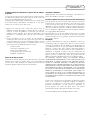
Important Grounding Requirements
•Air conditioner has a three-prong grounding plug on the power supply cord, which
must be plugged into a properly grounded three-prong wall receptacle for your
protection against possible shock hazard. For models up to and including 7.5 amperes
use a grounding type wall receptacle to match the cord plug.
Three-prong grounding plug.
DO NOT ALTER PLUG END.
Grounded three-prong wall
receptacle
Additional Safety Precautions
• Do not cut, alter or remove any of the expanded polystyrene (styrofoam) inside this
air conditioner.
• Do not store or use gasoline or other flammable vapors and liquids in the vicinity of
this or any other appliance. The fumes can create a fire hazard or explosion.
• Do not introduce objects in the air discharge area. This could cause permanent
damage to your unit.
• Do not pour liquids on the air conditioner as this could cause a malfunction. With the
unit unplugged, use a damp cloth for cleaning your unit.
• Avoid using strong solvents to clean the air conditioner.
• Clean the air conditioner filter every two weeks to avoid overheating caused by air
obstruction.
Do not operate without filter.
• Do not obstruct the air intake area of your air conditioner, as this could cause
overheating, thus activating the units security switch and shutting off the unit.
• Do not block air circulation to outside louvers of cabinet.
• Do not block air flow inside with blinds, curtains, or furniture, or outside with shrubs,
enclosures, or other buildings.
• Do not run the air conditioner with an outside protective cover in place. This could
result in fire or mechanical damage within the air conditioner.
A
A
B
B
125V
15A
ELECTRICAL REQUIREMENTS
& SAFETY PRECAUTIONS
INSTALLATION

2
WINDOW INSTALLATON
INSTALLATION
Tools Needed
Screwdrivers
Tape Measure
Carpenter’s Level
5/8” wood screws ....................9
Brackets....................................2
B
C
A
B
Installation Parts Kit
Window Requirements
Air conditioner is factory prepared for installation in standard
double hung windows (air conditioner cannot be installed in other
types of windows). The air conditioner can be installed in
windows 23” to 34” wide when filler panels are used. In windows
19” to 22” wide the air conditioner can be installed without the
filler panels. All windows must open at least 12 3/4” vertically.
Install the air conditioner in a window where there will be enough
clearance around the cabinet to allow ample circulation of air
through unit. All supporting parts should be secured to firm wood,
masonry, or metal.
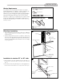
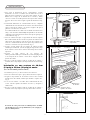
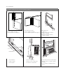
Filler Panel Installation
1. Place tabbed side of curtain in track on side of air conditioner
cabinet, and slide down the track until the curtain is even top
and bottom (Fig.1).
2. Slide the filler panel frame onto the air conditioner cabinet using
the tracks on the top and bottom of the unit. Slide the frame as
close to the air conditioner as possible so that the curtain locks
into place. Gently pull the frame out until it is the correct length
for your application.
Installation in window 23” to 34” wide
1. Open and mark center line of window. Measure and mark 6” to
the right of the center line and 6” to the left of the center line
(Fig. 2).
2. Place bracket so that the inside edge rests on the appropriate 6”
mark. Secure brackets with two (2) 1” long wood screws (Fig. 2).
1
Tabbed side
of curtain
Curtain
track
Filler panel frame
Curtain
Filler panel
frame track (top)
Filler panel
frame track
(bottom)
6"
6"
Center
of window
opening
5/8” Screws
Bracket
Bracket
Window Sill
5/8” Screws
2

3
WINDOW INSTALLATON
INSTALLATION
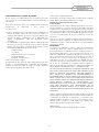
3. To overcome storm window interference, securely attach 2” wide
wood strips to the window stool and sill, with either nails or
screws. Strips should be as long as window opening and flush
with back side of stool. Thickness of strips should be controlled
by amount of interference (Fig. 3).
4. Keeping a firm grip on air conditioner, carefully center air
conditioner in window opening with the bottom bar between the
window stool and the angle bracket. Air conditioner should slant
slightly downward on the outside as shown by half a bubble off
on a carpenters level. This outward pitch prevents water from
entering the room (Fig. 3).
5. Close the window until it touches behind air conditioner top bar.
Slide filler panels outward until they touch window sash tracks.
(Do not release grip on air conditioner until lower window sash
is in final position) (Fig. 3).
6. Secure top of filler panels by driving 5/8” long wood screws into
window sash through mounting holes in top slides.
7. Secure bottom of filler panels by driving 5/8” long screws into
window sill through filler panel tabs.
8. Cut foam seal to width of window and install between upper and
lower window sash (Fig. 4).
Bracket
Upper
Window Sash
Wood Strips
(optional)
Lower
Window Sash
Level
3
Foam Seal
Lower
Window Sash
5/8” Wood Screws
Wood Sill
Filler Panel Tab
Caution: Do not drill a hole in bottom pan. Unit is designed to
operate with approximately 1/2” of water in bottom pan.
4
Nails / Screws
L-Bracket
Installation in window 19” to 22” wide
(Do not attach filler panels for this application)
1. Refer to steps 1 and 2 of preceding instructions.
2. Close window until it touches behind top bar (Fig. 4).
3. Fasten lower window sash to window frame using finishing nails,
wood screws, or “L” brackets (Fig. 5).
4. If filler is required on sides of air conditioner, cut foam seal to size
and fill both sides.
5. Cut foam seal to width of window and install between upper and
lower window sash (Fig. 4).
5

4
OPERATION
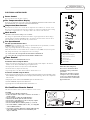
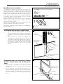
ELECTRONIC CONTROLS
ELECTRONIC CONTROL PANEL
Power Control
The Power Control turns the unit on and off.
The Temperature/Hour Display
Shows the set temperature or the timer setting. THE TEMPERATURE DISPLAY ONLY SHOWS THE
SET TEMPERATURE, NOT THE ACTUAL ROOM TEMPERATURE.
Temperature/Hour Controls
These buttons are used to raise or lower the set temperature in increments of 1° from 66° to 88°.
They also raise or lower the hour setting in increments of 1 from 00 to 24 when the timer is being
set. In order to toggle between °F or °C, depress both of the controls at the same time.
Mode Control
The Mode Control has two settings: FAN and COOL.
The settings are adjusted with the Mode Control button. A green light indicates which setting is
currently being used. When the COOL mode is selected, the unit will circulate and cool the air.
If the FAN mode is selected, the unit will only circulate the air.
Fan Speed Control
The Fan Speed Control has three
settings: High, Low and Auto. The settings are adjusted with the Fan Speed button, each time
the button is depressed it changes the
setting. A green light will indicate which setting is currently being used.
When the Auto feature is selected while the air conditioner is in the COOL mode, the fan speeds
will change automatically as the temperature in the room changes.
• 4° or more above the set temperature the unit will be in HI FAN mode.
• 4° or less above the set temperature the unit will be in LO FAN mode.
Timer Control
The timer can be set to either turn the unit on or off.
To turn the unit on using the Timer:
•Depress the timer key when the power is off, the display will read 00. Adjust to the desired
number of hours before TURN ON using the up/down arrows.
•The display will show the time by hours left until TURN ON.
•To Turn the timer off, depress the timer key.
•A green light next to the Timer Control indicates that the timer is set.
To turn the unit OFF using the Timer:
•Depress the timer key when the power is on, the display will read 00. Adjust to the desired number of hours
before TURN OFF using the up/down arrows. The display will automatically go back to the set temperature
after 10 seconds.
•To display the amount of time left until TURN OFF, depress the timer button once.
•To turn the TIMER OFF, depress the timer button twice.
•A green light next to the Timer Control indicates that the timer is set.
C
D
E
F
Power Control
Temperature/Timer Display
Temperature/Timer Controls
Mode Control
Fan Speed Control
Timer On/Off
A
B
C
D
E
F
A
B
C
D
E
F
A
B
Built-in three minute timing delay.
This electronic controlled unit will not
automatically resume operation after a
power failure.
If this electronic unit will not respond to
touch pad or remote control commands,
it is necessary to unplug the unit from the
electrical outlet for five seconds and then
plug the unit back in.
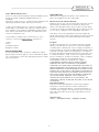
The functions work the same as your air conditioner’s touch controls.
Air Conditioner Remote Control
AAA
IEC R031.5V
+ -
AAA
IEC R03
1.5V
6
7
CAUTION:
• Use only AAA or IEC R03 1.5V batteries.
• Remove the batteries if the remote controller is not used for a
month or longer.
• Do not attempt to recharge the supplied batteries
• All batteries should be replaced at the same time.
• Do not dispose of the batteries in a fire as they may explode.
• Do not mix old and new batteries.
• Do not install the batteries with the polarity (+/–) reversed.
• Do not mix alkaline, standard (carbon - zinc), or rechargeable
(nickel-cadmium) batteries.
• Keep batteries and other things that could be swallowed away
from young children. Contact a doctor immediately if an
object is swallowed.

5
Occurrence Possible Cause Solutions
Air conditioner will not operate • Wall plug disconnected. ✔ Push plug firmly into wall outlet.
• House fuse blown or circuit breaker tripped. ✔ Replace fuse with time delay type
or reset circuit breaker.
• Unit turned off and then on too quickly. ✔ If air conditioner is turned off,
wait 3 minutes before restarting.
• Thermostat set too low for cooling. ✔ Adjust thermostat to higher setting for cooling.
Air from unit does not • Thermostat set too warm. ✔ Set thermostat to colder temperature.
feel cold enough • Room temperature below 70°F. ✔ Cooling may not occur until room
temperature rises above 70°F.
Air conditioner cooling, • Outdoor temperature below 70°F. ✔ To defrost the coil set thermostat to warmer
but room is too warm — position.
ice forming on cooling coil • Dirty air filter — air restricted. ✔ Clean filter. See “Cleaning the Air Filter” section.
behind decorative front
Air conditioner cooling, • Dirty air filter — air restricted. ✔ Clean air filter.
but room too warm — Refer to “Cleaning Air Filter” section.
NO ice forming on cooling coil • Thermostat set too warm. ✔ Set thermostat to colder setting.
behind decorative front
Noise when unit is cooling • Air movement sound. ✔ The sound of rushing air is normal. If too loud,
turn selector to lower fan setting.
• Sound of fan hitting water-moisture ✔ This is normal when humidity is high.
removal system. Close doors, windows and registers.
• Window vibration — poor installation. ✔ Refer to installation instructions —
check with installer.
Water dripping inside • Improper installation. ✔ Tilt air conditioner slightly to the outside to
when unit is cooling allow water drainage. Refer to installation
instructions — check with installer.
Water dripping outside • Unit removing large quantity of moisture ✔ This is normal during excessively humid days.
when unit is cooling from humid room.
Troubleshooting Guide
To save time and expense, check the following before calling an authorized service station.
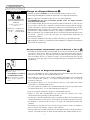
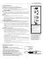
Remove screw
from both sides
of cabinet
Air Filter
Decorative Front
SERVICE
TROUBLESHOOTING
9
10
Decorative Front Removal
1. Turn the unit off and remove the plug from the outlet.
2. Remove the screws on either side of the cabinet (Fig. 9).
3. Gently pull forward while grasping both sides of the
decorative front.
4. To replace the decorative front, line up the top and bottom and
sides, and gently press into position.
5. Reattach the screws on both sides of the decorative front. Make
sure the decorative front is secure before reconnecting the plug
and operating the unit.
Cleaning the Air Filter
Every two weeks: Clean the Filter
1. Turn power to OFF.
2. Remove the air filter by grasping the top corners and pulling it
up and out of the unit (Fig. 8).
3. Wash in hot soapy water, rinse and shake dry.
4. Replace the filter, with the front of the filter toward you.
5. To dry the filter thoroughly, run your unit for a few minutes.
Remember, only a clean filter works properly and delivers top
efficiency at every setting.
Proper use and care of your air conditioner will help ensure
longer life of the unit. It is recommended to have the unit
inspected annually, as well as having the coils and
condensate water passages cleaned. Expense of the annual
inspection is the consumers’ responsibility.
8
Note: Failure to keep air filter clean will result in poor air
circulation.
DO NOT operate without filter. This can render the unit
inoperable.

6
SERVICE &
WARRANTY
Limited Warranty
(Within the 48 contiguous United States, State of Hawaii, the
District of Columbia, Puerto Rico and Canada).
Full (Five Year) Parts and Labor Warranty
During the first five years after the original date of purchase, CareCo
will, through it's authorized servicers and free of charge to the
owner or any subsequent owner, repair or replace any parts which
are defective in material or workmanship due to normal use. Ready
access to the air conditioner is the responsibility of the owner.
Note: In the event of any required parts replacement within the
period of this warranty, CareCo replacement parts shall be used and
will be warranted only for the period remaining on the original
warranty.
Exceptions
The above warranty does not cover failure to function caused by
damage to the unit while in your possession (other than damage
caused by defect or malfunction), or by it's improper installation, or
by unreasonable use of the unit, including without limitation, failure
to provide reasonable and necessary maintenance or to adhere to
the written Installation and Operating Instructions. If the unit is put
to commercial, business, rental, or other use or application other
than for consumer use, we make no warranties, express or implied.
Including but not limited to, any implied warranty of
merchantability or fitness for a particular use or purpose.
THE REMEDIES PROVIDED FOR IN THE ABOVE EXPRESS
WARRANTY ARE THE SOLE AND EXCLUSIVE REMEDIES
THEREFORE, NO OTHER EXPRESS WARRANTIES ARE MADE. ALL
IMPLIED WARRANTIES, INCLUDING BUT NOT LIMITED TO ANY
IMPLIED WARRANTY OF MERCHANTABILITY OR FITNESS FOR A
PARTICULAR USE OR PURPOSE, ARE LIMITED IN DURATION TO
FIVE YEARS FROM THE DATE OF ORIGINAL PURCHASE. IN NO
EVENT SHALL CARECO BE LIABLE FOR INDIRECT, INCIDENTAL,
OR CONSEQUENTIAL DAMAGES, EVEN IF ADVISED IN
ADVANCE OF THE POSSIBILITY OF SUCH DAMAGES. NO
WARRANTIES, EXPRESS OR IMPLIED, ARE MADE TO ANY BUYER
UPON RESALE.
Important Information
Some states do not allow limitations on how long an implied
warranty lasts or do not allow the exclusion or limitation of
incidental or consequential damages, so the above limitations or
exclusions may not apply to you. This warranty gives you specific
legal rights and you may also have other rights which vary from
state to state.
Administered By:
CareCo • 415 Wabash Avenue • Effingham, IL 62401
How to Obtain Warranty Service
Service for your Room Air Conditioner will be provided by CareCo
through its network of Authorized Independent Servicers
nationwide.
Note: Before calling for service, carefully read the "Installation and
Operating Instructions" booklet. Then if you need service:
1. Call a CareCo authorized service contractor and advise of the
model number, serial number, date of purchase and the nature of
your complaint. Service will be provided during normal working
hours. Contact your dealer for the name of an authorized service
contractor, if unknown to you.
2. If your dealer is unable to give you the name of a service
contractor or if you need other assistance, call CareCo at
1-800-332-6658
or write:
CareCo
415 Wabash Avenue
Effingham, IL 62401
Proof of Purchase Date
It is the responsibility of the consumer to establish the original
purchase date for warranty purposes. We recommend that a bill of
sale, canceled check or some other appropriate payment record be
kept for that purpose.
Page is loading ...
Page is loading ...
Page is loading ...
Page is loading ...
Page is loading ...
Page is loading ...
Page is loading ...
Page is loading ...
Page is loading ...
Page is loading ...
Page is loading ...
Page is loading ...
Page is loading ...
-
 1
1
-
 2
2
-
 3
3
-
 4
4
-
 5
5
-
 6
6
-
 7
7
-
 8
8
-
 9
9
-
 10
10
-
 11
11
-
 12
12
-
 13
13
-
 14
14
-
 15
15
-
 16
16
-
 17
17
-
 18
18
-
 19
19
-
 20
20


Air Temp B3X05F2A Owner's manual
- Category
- Split-system air conditioners
- Type
- Owner's manual
Ask a question and I''ll find the answer in the document
Finding information in a document is now easier with AI
in other languages
Related papers


Other documents
-
 Climette CA1226 Installation guide
-
 Hampton Bay HBX050 Owner's manual
-
Fedders 23-23-0335N-007 s Installation & Operation Manual
-
Fedders 23-23-0363N-002 Installation & Operation Manual
-
Whirlpool ACQ082PS5 Owner's manual
-
-
Fedders a7y12f2b User manual
-
Maytag 23-11-2229N-004 User manual
-
-

