ParkZone UM F-27Q Stryker 180 BNF User manual
- Category
- Remote controlled toys
- Type
- User manual
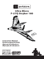
ParkZone UM F-27Q Stryker 180 BNF: Get ready to experience exhilarating speed and climb performance with the ultra-micro aircraft that packs a punch. Its 180BL 3000Kv brushless outrunner motor delivers an exciting flying experience, while the functional twin rudders allow for extreme aerobatic maneuvers. Enjoy smooth and predictable flight characteristics, making it a favorite among sport pilots.
ParkZone UM F-27Q Stryker 180 BNF: Get ready to experience exhilarating speed and climb performance with the ultra-micro aircraft that packs a punch. Its 180BL 3000Kv brushless outrunner motor delivers an exciting flying experience, while the functional twin rudders allow for extreme aerobatic maneuvers. Enjoy smooth and predictable flight characteristics, making it a favorite among sport pilots.


-
 1
1
-
 2
2
-
 3
3
-
 4
4
-
 5
5
-
 6
6
-
 7
7
-
 8
8
-
 9
9
-
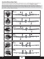 10
10
-
 11
11
-
 12
12
-
 13
13
-
 14
14
-
 15
15
-
 16
16
-
 17
17
-
 18
18
-
 19
19
-
 20
20
-
 21
21


ParkZone UM F-27Q Stryker 180 BNF User manual
- Category
- Remote controlled toys
- Type
- User manual
ParkZone UM F-27Q Stryker 180 BNF: Get ready to experience exhilarating speed and climb performance with the ultra-micro aircraft that packs a punch. Its 180BL 3000Kv brushless outrunner motor delivers an exciting flying experience, while the functional twin rudders allow for extreme aerobatic maneuvers. Enjoy smooth and predictable flight characteristics, making it a favorite among sport pilots.
Ask a question and I''ll find the answer in the document
Finding information in a document is now easier with AI
Related papers
-
ParkZone F-27Q Stryker User manual
-
-
-
ParkZone Archer User manual
-
ParkZone VisionAire BNF User manual
-
-
ParkZone ICON A5 PNP User manual
-
ParkZone PKZ5980 User manual
-
ParkZone Spitfire Mk IX PNP User manual
-
ParkZone S.E.5a WWI PNP User manual
Other documents
-
WALI GSDM003 User manual
-
E-flite Celectra User manual
-
E-flite UMX Vapor Lite HP RTF User manual
-
BNF P-51D Mustang 280 User manual
-
E-flite UMX Spacewalker User manual
-
-
E-flite UMX MiG 15 DF User manual
-
Horizon Hobby UMX J-3 Cub User manual
-
E-flite The Beast User manual
-
Spektrum DX6i Assembly Manual