Page is loading ...

AC Power
For Business-Critical Continuity™
Liebert
®
GXT3-10000T230
™
User Manual–10kVA, 50/60 Hz, 230V


i
TABLE OF CONTENTS
IMPORTANT SAFETY INSTRUCTIONS . . . . . . . . . . . . . . . . . . . . . . . . . . . . . . . . . . . . . . . . . . . . . . . .1
1.0 INTRODUCTION AND SYSTEM DESCRIPTION . . . . . . . . . . . . . . . . . . . . . . . . . . . . . . . . . . . . .5
1.1 Device Overview . . . . . . . . . . . . . . . . . . . . . . . . . . . . . . . . . . . . . . . . . . . . . . . . . . . . . . . . . . . . . 6
1.2 Options . . . . . . . . . . . . . . . . . . . . . . . . . . . . . . . . . . . . . . . . . . . . . . . . . . . . . . . . . . . . . . . . . . . . 6
1.2.1 External Battery Cabinets . . . . . . . . . . . . . . . . . . . . . . . . . . . . . . . . . . . . . . . . . . . . . . . . . . . . . . 6
1.2.2 Optional Interfaces . . . . . . . . . . . . . . . . . . . . . . . . . . . . . . . . . . . . . . . . . . . . . . . . . . . . . . . . . . . . 6
2.0 UNPACKING THE UPS AND SITE PREPARATION . . . . . . . . . . . . . . . . . . . . . . . . . . . . . . . . . .7
2.1 Inspection . . . . . . . . . . . . . . . . . . . . . . . . . . . . . . . . . . . . . . . . . . . . . . . . . . . . . . . . . . . . . . . . . . 7
2.2 Required Setup Equipment . . . . . . . . . . . . . . . . . . . . . . . . . . . . . . . . . . . . . . . . . . . . . . . . . . . . 7
2.3 Unpacking. . . . . . . . . . . . . . . . . . . . . . . . . . . . . . . . . . . . . . . . . . . . . . . . . . . . . . . . . . . . . . . . . . 7
2.4 Storage . . . . . . . . . . . . . . . . . . . . . . . . . . . . . . . . . . . . . . . . . . . . . . . . . . . . . . . . . . . . . . . . . . . . 7
2.5 Handling . . . . . . . . . . . . . . . . . . . . . . . . . . . . . . . . . . . . . . . . . . . . . . . . . . . . . . . . . . . . . . . . . . . 7
2.6 Environmental Conditions. . . . . . . . . . . . . . . . . . . . . . . . . . . . . . . . . . . . . . . . . . . . . . . . . . . . . 8
2.7 Access required. . . . . . . . . . . . . . . . . . . . . . . . . . . . . . . . . . . . . . . . . . . . . . . . . . . . . . . . . . . . . . 8
2.8 Floor/Rack Loading . . . . . . . . . . . . . . . . . . . . . . . . . . . . . . . . . . . . . . . . . . . . . . . . . . . . . . . . . . 8
2.9 Inventory List . . . . . . . . . . . . . . . . . . . . . . . . . . . . . . . . . . . . . . . . . . . . . . . . . . . . . . . . . . . . . . . 8
2.10 Clearance . . . . . . . . . . . . . . . . . . . . . . . . . . . . . . . . . . . . . . . . . . . . . . . . . . . . . . . . . . . . . . . . . . 8
2.11 Repacking the UPS. . . . . . . . . . . . . . . . . . . . . . . . . . . . . . . . . . . . . . . . . . . . . . . . . . . . . . . . . . . 8
3.0 INSTALLATION . . . . . . . . . . . . . . . . . . . . . . . . . . . . . . . . . . . . . . . . . . . . . . . . . . . . . . . . . .9
3.1 Electrical preparations. . . . . . . . . . . . . . . . . . . . . . . . . . . . . . . . . . . . . . . . . . . . . . . . . . . . . . . . 9
3.2 Current Table and Suggested Cable Sizes . . . . . . . . . . . . . . . . . . . . . . . . . . . . . . . . . . . . . . . . 9
3.3 Neutral Connection . . . . . . . . . . . . . . . . . . . . . . . . . . . . . . . . . . . . . . . . . . . . . . . . . . . . . . . . . 10
3.4 External Protection and Isolating Devices . . . . . . . . . . . . . . . . . . . . . . . . . . . . . . . . . . . . . . . 10
3.5 Installation of Differential Protection Devices . . . . . . . . . . . . . . . . . . . . . . . . . . . . . . . . . . . . 11
3.6 External Electrical Connections . . . . . . . . . . . . . . . . . . . . . . . . . . . . . . . . . . . . . . . . . . . . . . . 11
3.7 Connecting Mains and Load . . . . . . . . . . . . . . . . . . . . . . . . . . . . . . . . . . . . . . . . . . . . . . . . . . 12
3.8 Terminal Blocks for UPS . . . . . . . . . . . . . . . . . . . . . . . . . . . . . . . . . . . . . . . . . . . . . . . . . . . . . 13
3.9 Connecting Power Cables. . . . . . . . . . . . . . . . . . . . . . . . . . . . . . . . . . . . . . . . . . . . . . . . . . . . . 13
3.10 External Tower Batteries. . . . . . . . . . . . . . . . . . . . . . . . . . . . . . . . . . . . . . . . . . . . . . . . . . . . . 14
3.11 Connecting an External Battery Extension . . . . . . . . . . . . . . . . . . . . . . . . . . . . . . . . . . . . . . 14
3.12 Battery Precautions . . . . . . . . . . . . . . . . . . . . . . . . . . . . . . . . . . . . . . . . . . . . . . . . . . . . . . . . . 15
3.13 Configuration Program . . . . . . . . . . . . . . . . . . . . . . . . . . . . . . . . . . . . . . . . . . . . . . . . . . . . . . 15
3.14 Liebert
®
GXT3-10000T230
™
Configuration Program Features . . . . . . . . . . . . . . . . . . . . . . 15
3.15 What You Will Need. . . . . . . . . . . . . . . . . . . . . . . . . . . . . . . . . . . . . . . . . . . . . . . . . . . . . . . . . 15
4.0 OPERATION . . . . . . . . . . . . . . . . . . . . . . . . . . . . . . . . . . . . . . . . . . . . . . . . . . . . . . . . . . .16
4.1 Normal Operating . . . . . . . . . . . . . . . . . . . . . . . . . . . . . . . . . . . . . . . . . . . . . . . . . . . . . . . . . . 16
4.1.1 Block diagram . . . . . . . . . . . . . . . . . . . . . . . . . . . . . . . . . . . . . . . . . . . . . . . . . . . . . . . . . . . . . . . 16

ii
4.2 Control Panel . . . . . . . . . . . . . . . . . . . . . . . . . . . . . . . . . . . . . . . . . . . . . . . . . . . . . . . . . . . . . . 17
4.2.1 Controls and Messages. . . . . . . . . . . . . . . . . . . . . . . . . . . . . . . . . . . . . . . . . . . . . . . . . . . . . . . . 17
4.2.2 Warning Indicators. . . . . . . . . . . . . . . . . . . . . . . . . . . . . . . . . . . . . . . . . . . . . . . . . . . . . . . . . . . 20
4.2.3 Fault Indicators . . . . . . . . . . . . . . . . . . . . . . . . . . . . . . . . . . . . . . . . . . . . . . . . . . . . . . . . . . . . . 21
4.3 Startup Preparations . . . . . . . . . . . . . . . . . . . . . . . . . . . . . . . . . . . . . . . . . . . . . . . . . . . . . . . . 21
4.4 UPS Startup Procedure - Single Block . . . . . . . . . . . . . . . . . . . . . . . . . . . . . . . . . . . . . . . . . . 22
4.5 UPS Shutdown Procedure—All Ratings . . . . . . . . . . . . . . . . . . . . . . . . . . . . . . . . . . . . . . . . . 22
4.6 Maintenance Bypass Procedure. . . . . . . . . . . . . . . . . . . . . . . . . . . . . . . . . . . . . . . . . . . . . . . . 22
4.7 Return from Maintenance Bypass Procedure . . . . . . . . . . . . . . . . . . . . . . . . . . . . . . . . . . . . . 23
4.8 Functional Test. . . . . . . . . . . . . . . . . . . . . . . . . . . . . . . . . . . . . . . . . . . . . . . . . . . . . . . . . . . . . 23
4.9 Remote Emergency Power Off . . . . . . . . . . . . . . . . . . . . . . . . . . . . . . . . . . . . . . . . . . . . . . . . . 23
4.10 Self-Tests. . . . . . . . . . . . . . . . . . . . . . . . . . . . . . . . . . . . . . . . . . . . . . . . . . . . . . . . . . . . . . . . . . 24
4.10.1 Lamp Test . . . . . . . . . . . . . . . . . . . . . . . . . . . . . . . . . . . . . . . . . . . . . . . . . . . . . . . . . . . . . . . . . . 24
4.10.2 Battery Test . . . . . . . . . . . . . . . . . . . . . . . . . . . . . . . . . . . . . . . . . . . . . . . . . . . . . . . . . . . . . . . . 24
5.0 MAINTENANCE . . . . . . . . . . . . . . . . . . . . . . . . . . . . . . . . . . . . . . . . . . . . . . . . . . . . . . . . .25
5.1 Testing, Replacing and Disposing of Batteries . . . . . . . . . . . . . . . . . . . . . . . . . . . . . . . . . . . . 25
5.2 Easy Battery Replacement. . . . . . . . . . . . . . . . . . . . . . . . . . . . . . . . . . . . . . . . . . . . . . . . . . . . 26
5.3 Storage . . . . . . . . . . . . . . . . . . . . . . . . . . . . . . . . . . . . . . . . . . . . . . . . . . . . . . . . . . . . . . . . . . . 27
5.4 Cleaning . . . . . . . . . . . . . . . . . . . . . . . . . . . . . . . . . . . . . . . . . . . . . . . . . . . . . . . . . . . . . . . . . . 27
6.0 COMMUNICATION . . . . . . . . . . . . . . . . . . . . . . . . . . . . . . . . . . . . . . . . . . . . . . . . . . . . . . .28
6.1 Communication Interface Port . . . . . . . . . . . . . . . . . . . . . . . . . . . . . . . . . . . . . . . . . . . . . . . . 28
6.2 Terminal Block . . . . . . . . . . . . . . . . . . . . . . . . . . . . . . . . . . . . . . . . . . . . . . . . . . . . . . . . . . . . . 28
6.2.1 Any Mode Shutdown . . . . . . . . . . . . . . . . . . . . . . . . . . . . . . . . . . . . . . . . . . . . . . . . . . . . . . . . . 28
6.2.2 Battery Mode Shutdown . . . . . . . . . . . . . . . . . . . . . . . . . . . . . . . . . . . . . . . . . . . . . . . . . . . . . . 29
6.2.3 On Battery . . . . . . . . . . . . . . . . . . . . . . . . . . . . . . . . . . . . . . . . . . . . . . . . . . . . . . . . . . . . . . . . . 29
6.2.4 Low Battery . . . . . . . . . . . . . . . . . . . . . . . . . . . . . . . . . . . . . . . . . . . . . . . . . . . . . . . . . . . . . . . . 29
6.3 Liebert IntelliSlot
®
Communication Cards. . . . . . . . . . . . . . . . . . . . . . . . . . . . . . . . . . . . . . . 29
6.3.1 Liebert
®
MultiLink
®. . . . . . . . . . . . . . . . . . . . . . . . . . . . . . . . . . . . . . . . . . . . . . . . . . . . . . . . . . . . . . . . . . . . . . . . . .30
6.4 Remote Emergency Power Off . . . . . . . . . . . . . . . . . . . . . . . . . . . . . . . . . . . . . . . . . . . . . . . . . 30
7.0 TROUBLESHOOTING . . . . . . . . . . . . . . . . . . . . . . . . . . . . . . . . . . . . . . . . . . . . . . . . . . . . .31
8.0 S
PECIFICATIONS . . . . . . . . . . . . . . . . . . . . . . . . . . . . . . . . . . . . . . . . . . . . . . . . . . . . . . . .32

iii
FIGURES
Figure 1 Liebert GXT3-10000T230 control panel . . . . . . . . . . . . . . . . . . . . . . . . . . . . . . . . . . . . . . . . . . . . . . 5
Figure 2 Liebert GXT3-10000T230 front and rear views . . . . . . . . . . . . . . . . . . . . . . . . . . . . . . . . . . . . . . . . 6
Figure 3 Unpacking . . . . . . . . . . . . . . . . . . . . . . . . . . . . . . . . . . . . . . . . . . . . . . . . . . . . . . . . . . . . . . . . . . . . . . 7
Figure 4 Standard configuration - differential breaker . . . . . . . . . . . . . . . . . . . . . . . . . . . . . . . . . . . . . . . . . 11
Figure 5 Side view . . . . . . . . . . . . . . . . . . . . . . . . . . . . . . . . . . . . . . . . . . . . . . . . . . . . . . . . . . . . . . . . . . . . . . 11
Figure 6 Input and output connections with single source, single-phase input supply. . . . . . . . . . . . . . . . 12
Figure 7 Input and output connections with dual source, single-phase input supplies. . . . . . . . . . . . . . . . 12
Figure 8 Input and output connections with single source, three-phase input supply . . . . . . . . . . . . . . . . 12
Figure 9 Input and output connections with dual source, three-phase UPS, single-phase bypass
input supplies . . . . . . . . . . . . . . . . . . . . . . . . . . . . . . . . . . . . . . . . . . . . . . . . . . . . . . . . . . . . . . . . . . 13
Figure 10 Hardwire terminals. . . . . . . . . . . . . . . . . . . . . . . . . . . . . . . . . . . . . . . . . . . . . . . . . . . . . . . . . . . . . . 13
Figure 11 Liebert GXT3 10000T230 with External Battery Cabinet . . . . . . . . . . . . . . . . . . . . . . . . . . . . . . . 14
Figure 12 Overview of UPS tower. . . . . . . . . . . . . . . . . . . . . . . . . . . . . . . . . . . . . . . . . . . . . . . . . . . . . . . . . . . 16
Figure 13 Control panel . . . . . . . . . . . . . . . . . . . . . . . . . . . . . . . . . . . . . . . . . . . . . . . . . . . . . . . . . . . . . . . . . . . 17
Figure 14 System block, menu structure . . . . . . . . . . . . . . . . . . . . . . . . . . . . . . . . . . . . . . . . . . . . . . . . . . . . . 18
Figure 15 REPO connections. . . . . . . . . . . . . . . . . . . . . . . . . . . . . . . . . . . . . . . . . . . . . . . . . . . . . . . . . . . . . . . 24
Figure 16 Removing front panel and unlocking battery trays . . . . . . . . . . . . . . . . . . . . . . . . . . . . . . . . . . . . 26
Figure 17 Disconnecting battery tray and battery packs . . . . . . . . . . . . . . . . . . . . . . . . . . . . . . . . . . . . . . . . 26
Figure 18 Terminal block pin layout. . . . . . . . . . . . . . . . . . . . . . . . . . . . . . . . . . . . . . . . . . . . . . . . . . . . . . . . . 28
Figure 19 REPO switch connection diagram . . . . . . . . . . . . . . . . . . . . . . . . . . . . . . . . . . . . . . . . . . . . . . . . . . 30
TABLES
Table 1 Overview of UPS devices and batteries . . . . . . . . . . . . . . . . . . . . . . . . . . . . . . . . . . . . . . . . . . . . . . . 6
Table 2 Connection data . . . . . . . . . . . . . . . . . . . . . . . . . . . . . . . . . . . . . . . . . . . . . . . . . . . . . . . . . . . . . . . . . 9
Table 3 External protection device data . . . . . . . . . . . . . . . . . . . . . . . . . . . . . . . . . . . . . . . . . . . . . . . . . . . . 10
Table 4 Lighted LEDs . . . . . . . . . . . . . . . . . . . . . . . . . . . . . . . . . . . . . . . . . . . . . . . . . . . . . . . . . . . . . . . . . . 17
Table 5 Displayed text—system block and main menu . . . . . . . . . . . . . . . . . . . . . . . . . . . . . . . . . . . . . . . . 19
Table 6 Warning indicators . . . . . . . . . . . . . . . . . . . . . . . . . . . . . . . . . . . . . . . . . . . . . . . . . . . . . . . . . . . . . . 20
Table 7 Display faults . . . . . . . . . . . . . . . . . . . . . . . . . . . . . . . . . . . . . . . . . . . . . . . . . . . . . . . . . . . . . . . . . . 21
Table 8 Battery test report messages . . . . . . . . . . . . . . . . . . . . . . . . . . . . . . . . . . . . . . . . . . . . . . . . . . . . . . 24
Table 9 Replacement battery pack . . . . . . . . . . . . . . . . . . . . . . . . . . . . . . . . . . . . . . . . . . . . . . . . . . . . . . . . 25
Table 10 Troubleshooting - errors and corrective action . . . . . . . . . . . . . . . . . . . . . . . . . . . . . . . . . . . . . . . . 31
Table 11 UPS specifications. . . . . . . . . . . . . . . . . . . . . . . . . . . . . . . . . . . . . . . . . . . . . . . . . . . . . . . . . . . . . . . 32
Table 12 Environmental data . . . . . . . . . . . . . . . . . . . . . . . . . . . . . . . . . . . . . . . . . . . . . . . . . . . . . . . . . . . . . 34
Table 13 Agency/safetycompliance . . . . . . . . . . . . . . . . . . . . . . . . . . . . . . . . . . . . . . . . . . . . . . . . . . . . . . . . . 34
Table 14 Operating temperature parameters. . . . . . . . . . . . . . . . . . . . . . . . . . . . . . . . . . . . . . . . . . . . . . . . . 34
Table 15 Typical battery run times, minutes at 25°C (77°F), 100% resistive load. . . . . . . . . . . . . . . . . . . . 34

iv

1
IMPORTANT SAFETY INSTRUCTIONS
SAVE THESE INSTRUCTIONS
This manual contains important safety instructions that must be followed when installing, operating
and maintaining the Liebert
®
GXT3-10000T230
™
uninterruptible power system (UPS).
Read all safety, installation and operating instructions before installing or operating the UPS. Adhere
to all warnings on the unit and in this manual. Follow all operating and user instructions.
The Liebert GXT3-10000T230 is not intended for use with life support or other designated critical
devices. The UPS is designed for data processing equipment. If uncertain the intended use for this
UPS, consult your dealer or Emerson
®
representative.
This device serves as an uninterruptible power supply for connected loads. Maximum load must not
exceed that shown on the UPS rating label. The device is in compliance with all relevant safety
regulations concerning information technology equipment, including electronic machines for use in an
office environment.
Depending on the type and rating of UPS device, certain configurations of battery extensions may be
connected. These battery extensions may be connected only to the compatible basic UPS unit.
!
WARNING
Opening or removing the cover may expose you to lethal voltages within this unit even when
it is apparently not operating and the input wiring is disconnected from the electrical source.
Observe all cautions and warnings in this manual. Failure to do so may result in serious
injury or death. Refer all UPS and battery service to qualified service personnel. Do not
attempt to service this product yourself. Never work alone.
!
WARNING
Emerson considers the safety of personnel to be of paramount importance. For this reason it is
essential that procedures relating to safety be studied before commencing work and properly
adhered to thereafter.
The user or operator may intervene in the operation of the UPS provided that the instructions
laid out in Notes Regarding the EU Declaration of Conformity on page 3 are strictly
adhered to.
The installation of the UPS, described in Installation on page 9, may only be carried out by
qualified technical personnel.
Even when all switches and interrupters are open, hazardous voltages are present within the
UPS; any operation that requires protective panels to be opened or removed may be carried
out by Emerson-authorized technical personnel only.

2
!
CAUTION
Carefully read the following safety notices. Failure to observe the instructions may endanger
your life, your health, the reliability of your device and the security of your data.
• Transport the unit only in suitable packaging (protected against jolts and shocks).
• If the equipment is moved from a cold environment to the operating room, condensation
may occur. Before you switch On the equipment, it must be absolutely dry. An acclimatiza-
tion period of at least two hours is required.
• The equipment must be installed in accordance with the environmental conditions specified
in 2.6 - Environmental Conditions and in Table 12 - Environmental data.
• Even with all switches in the “OFF” position (see Figure 13 - Control panel) the UPS is
not isolated from the mains. To isolate completely from the mains, the power cables must be
disconnected.
• In case of interruption of the mains voltage, the integrated battery maintains the power
supply to the user equipment.
• Lay all cables so that nobody can stand on them or trip over them. When connecting the
UPS to the power supply, follow the instructions in 2.0 - Unpacking the UPS and Site
Preparation.
• Make sure that no objects (e.g., pins, necklaces, paper clips, etc.) get inside the device.
• In emergencies (e.g., damaged case, controls or power cables, penetration of liquids or for-
eign matter), switch Off the device and contact the appropriate customer service represen-
tative.
• Do not connect equipment that will overload the UPS (e.g., laser printers or vacuum clean-
ers) or demand DC-current (e.g., half-wave rectifiers).
• When cleaning the unit, follow the instructions in 5.0 - Maintenance.
• The sum of the leakage currents (protective conductor current) of the UPS and the con-
nected devices exceeds 3.5 mA for all ratings of the UPS. Earth connection is essential
before connecting supply.
• Data transmission lines should not be connected or disconnected during a thunderstorm.
• Remote Emergency Power Off (REPO) input is located on the rear of the unit (see 3.8 - Ter-
minal Blocks for UPS). When this connection is open, the logic circuit will immediately
shut down the UPS output.
• An Emergency Switching Device (E.S.D.) must be fitted downstream of the UPS for the wir-
ing installation safety to comply with the European Harmonized Document HD384-4-46 S1.
• Maintenance bypass switch is for the use of service personnel only. It is located under the
rear cover. Open the safety cover to operate the maintenance bypass switch.
• The Tower UPS may be connected either to 3-phase mains or single-phase mains. Therefore
the right input terminals have to be connected (see 3.7 - Connecting Mains and Load).
The UPS autosensing mode ensures that it adapts to the connected mains supply.
• This equipment complies with IEC 61000-3-12 provided that the short-circuit ratio Rsce is
greater than or equal to 250 at the interface point between the user’s supply and the public
system. It is the responsibility of the installer or user of the equipment to ensure, by consul-
tation with the distribution network operator if necessary, that the equipment is connected
only to a supply with a short-circuit ratio Rsce greater than or equal to 250.
• For three-phase equipment, the disconnect device shall disconnect simultaneously all line
conductors of the AC mains supply. For equipment requiring a neutral connection to an IT
power distribution system, the disconnect device shall be a four-pole device and shall dis-
connect all line conductors and the neutral conductor.

3
Radio Interference
The Liebert GXT3-10000T230 is a Radio Interference Class A Product.
The UPS device may cause radio interference. Do not place it near devices that are particularly
susceptible to electromagnetic interference (e.g., transmitters, receivers, radar, metal detectors and
antitheft devices).
NOTICE
This is a product for commercial and industrial application in the second environment.
Installation restrictions or additional measures may be needed to prevent disturbances. The
product can meet the requirement of category C2 and may be used in residential, commercial
and light industrial areas.
Notes Regarding the EU Declaration of Conformity
The Liebert GXT3-10000T230 conforms to the following European directives:
• 2006/95/EC—Directive of the council for adaptation of the legal regulations of the member states
regarding electrical equipment for use within specific voltage limits.
• 2004/108/EC—Directive of the council for adaptation of the legal regulations of the member
states regarding electromagnetic compatibility.
Conformity is established through compliance with the following standards:
• EN 62040-1-1
• EN 62040-2
• EN61000-3-12
• EN61000-3-11
Additional information regarding adherence to these directives is included in the appendices NSR
and EMC of the EU Declaration of Conformity.
If required, the EU Declaration of Conformity may be requested from Emerson
®
.
NOTICE TO EUROPEAN UNION CUSTOMERS: DISPOSAL OF OLD APPLIANCES—This
product has been supplied from an environmentally aware manufacturer that complies with the
Waste Electrical and Electronic Equipment (WEEE) Directive 2002/96/CE.
!
CAUTION
Do not connect more than two Liebert
®
GXT3-240TBATTCE
™
battery extensions to the
Liebert GXT3-10000T230
™
.
The vents for air intake and outlet at the front and rear side must not be obstructed.
The sum of the leakage currents (protective conductor current) of the UPS and the connected
devices exceeds 3.5 mA. Earth connection of the unit is essential before connecting supply.
!
CAUTION
The supply to the load may be interrupted by opening all the switches or by turning the
Maintenance Switch on the rear of the UPS to the Off position.
DO NOT USE WATER to extinguish any fires that may occur in the area where the UPS is
installed.
!
CAUTION
Leakage currents
Connect the protection earth (PE) safety conductor before connecting any other cables.

4
The “crossed-out wheelie bin” symbol at right is placed on this product to
encourage recycling wherever possible. Please be environmentally responsible
and recycle this product through your recycling facility at its end of life. Do
not dispose of this product as unsorted municipal waste. Follow local
municipal waste ordinances for proper disposal provisions to reduce the
environmental impact of waste electrical and electronic equipment (WEEE).
For information regarding the scrapping of this equipment, go to
http://www.eu.emersonnetworkpower.com
Click on Products or Contacts and follow the links to obtain assistance.
Information is also available by telephoning our worldwide technical support:
• Toll free: 00 80011554499
• Toll number (in Italy): +39 0298250222

Introduction and System Description
5
1.0 INTRODUCTION AND SYSTEM DESCRIPTION
Congratulations on your purchase of the Liebert
®
GXT3-10000T230
™
. This system provides
conditioned power to microcomputers and other sensitive electronic equipment.
Upon generation, AC power is clean and stable. However, during transmission and distribution it is
subject to voltage sags, spikes and complete power failure that may interrupt computer operations,
cause data loss and damage equipment. The Liebert GXT3-10000T230 protects equipment from these
disturbances.
The Liebert GXT3-10000T230 is a compact, on-line UPS. An on-line UPS continuously conditions and
regulates its output voltage whether utility power is present or not. It supplies connected equipment
with clean sinewave power. Sensitive electronic equipment operates best from sinewave power.
For ease of use, the Liebert GXT3-10000T230 features an LCD display for comprehensive user
indications and programmable controls. It also provides self-diagnostic tests.
The Liebert GXT3-10000T230 has an interface port for communication between the UPS and a
network server or other computer system. This port provides detailed operating information including
voltages, currents and alarm status to the host system when used in conjunction with Liebert’s
MultiLink
®
software.
Figure 1 Liebert GXT3-10000T230 control panel
!
CAUTION
This UPS may only be operated by qualified personnel.

Introduction and System Description
6
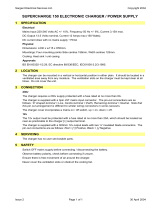
1.1 Device Overview
The Liebert
®
GXT3-10000T230
™
is available at various nominal power ratings.
The following table provides an overview of the various versions of the device:
Figure 2 Liebert GXT3-10000T230 front and rear views
1.2 Options
1.2.1 External Battery Cabinets
Optional external battery cabinets are available to extend UPS autonomy in the event of mains
interruption. The cabinets have the same dimensions, color scheme and design as the Liebert
GXT3-10000T230.
For technical data about external battery cabinets see Table 11 - UPS specifications.
For connection notices see Table 2 - Connection data.
1.2.2 Optional Interfaces
Refer to 6.0 - Communication for details.
Table 1 Overview of UPS devices and batteries
Type Model # Nominal power
UPS with integrated battery Liebert GXT3-10000T230 10000 VA/ 9000W
Battery cabinet Liebert GXT3-240TBATTCE 240VDC
Control
Panel
Control
Keys
Liquid
Crystal
Display
Ventilation
Louvers
Liebert IntelliSlot
port (covered)
REPO Contacts
Maintenance
Bypass Switch
Parallel Port
Parallel Port
Bypass
Source Input
Circuit
Breaker
Input Breaker
Hardwire Input
and Output
Connector
Terminal Block
Cooling Fans
External
Battery
Connector
Block
Output Breaker

Unpacking the UPS and Site Preparation
7
2.0 UNPACKING THE UPS AND SITE PREPARATION
2.1 Inspection
Upon receiving your Liebert
®
GXT3-10000T230
™
, examine the packaging for any signs of
mishandling or damage. While removing the packaging materials, inspect the UPS for damage. If any
damage is noted, notify your local Emerson
®
representative and carrier. Any damage or missing parts
must be reported to the supplier within eight days of delivery.
2.2 Required Setup Equipment
The following tools are required to set up your UPS:
•pallet jack
• utility knife or scissors
• star head screwdriver
2.3 Unpacking
Take care when removing the packaging to avoid damaging the UPS. Do not dispose of the packing
material. The original packaging material should be used if the UPS needs to be repackaged, such as
for shipping. Check all packaging to ensure that no items are accidentally discarded. Remove the
packaging in the sequence shown below.
Figure 3 Unpacking
2.4 Storage
If the UPS will not be installed immediately, store the unit indoors in a clean and dry area. Protect all
the equipment, including its batteries, from extreme temperature, high humidity, spills and other
damaging conditions. Refer to Table 12 for permissible environmental conditions for storage.
2.5 Handling
The equipment must be kept upright at all times and handled with care. It may be damaged if
dropped or subjected to severe impact.
Unlock
Plywood Case
Ramp in Slot
on Shipping
Pallet
Cushion
Ramp
Cushion
Pallet Jack
Cushions

Unpacking the UPS and Site Preparation
8
2.6 Environmental Conditions
The Liebert
®
GXT3-10000T230
™
must be installed vertically, on a level and even surface and in an
area protected from extreme temperatures, water, humidity and the presence of conductive powder or
dust (see Table 12). Do not stack units; do not place any objects on top of a unit.
2.7 Access required
The area must have sufficient space for installation procedures and for routine maintenance. Access
doors must be sufficiently large to permit passage of the UPS.
2.8 Floor/Rack Loading
Ensure that the floor where the UPS/batteries will be installed will support the unit’s weight (see
Table 11 for the unit’s weight).
2.9 Inventory List
The Liebert GXT3-10000T230 comes with:
• CD containing:
• Liebert MultiLink
®
Shutdown Software
•Configuration Software
• User Manual
•USB cable
• Terminal block communication terminals
• Floor mount brackets
• Input power configuration jumpers
• Paralleling cable
2.10 Clearance
The UPS is fitted with wheels for ease of movement over short distances. Leave 300mm (12in.)
around the sides and rear of the unit to allow a flow of air and to provide access for any routine
maintenance that may involve removal of the panels.
2.11 Repacking the UPS
To repack the UPS, proceed as follows:
1. Do not pack the equipment until at least six hours have elapsed since the last recharge.
2. Make sure to re-use the original packing material to ship the UPS.

Installation
9
3.0 INSTALLATION
3.1 Electrical preparations
Before you begin installation, the input source must be isolated and secured to prevent reconnection
during installation. The input circuit breaker on the rear of the UPS must be in the Off position.
For electrical installation, the nominal current rating of the source must be observed. The UPS is not
suitable for connection to 16A subdistribution systems.
3.2 Current Table and Suggested Cable Sizes
The following table indicates the currents and recommended sizes of the connecting cables in
accordance with regulations IEC-287 and DIN VDE 0298
1. PVC-insulated copper cables (@ 70°C) (158°F).
2. Air temperature surrounding the conduits should not be greater than 30°C (86°F).
When the UPS is in Bypass mode, the entire output current of the UPS is passed through the phase
L1 and Neutral cables. To simplify connection data, no distinction has been made between phase L1
and phases L2 and L3. The cable sizes are defined for the maximum current carried by the output
cables.
!
WARNING
Installation may be carried out only by qualified technicians, conforming to applicable safety
standards.
Electric shock hazard: Even when the unit is disconnected from the mains, hazardous voltage
may still be supplied by the battery. Both poles should be disconnected before carrying out
maintenance work inside the UPS.
NOTE
Should there be any variation in the conditions, it will be necessary to verify whether the cable
dimensions satisfy the requirements of IEC-287 and DIN VDE 0298. In cases where the cables
are so long that they cause a drop in voltage of >3%, a larger size must be used.
Table 2 Connection data
Description
Unit UPS Power Rating
kVA
10 - 1/1 10 - 3/1
Connector size mm
2
10 10
Max input current Arms 53 53
Input cable size
(and neutral)
mm
2
10 10
Max output current Arms 51 51
Output cable size
(and neutral)
mm
2
10 10
Earth cable size mm
2
10 10
!
WARNING
Particularly sensitive equipment may be susceptible to interference. To prevent this,
Emerson
®
suggests:
Mains input, output and external battery cables to the UPS in earthed, metal conduits, or use
shielded cables
Routing of cables (e.g. power supplies, communication or data lines) to other equipment,
should be kept separate from that of UPS cables.

Installation
10
3.3 Neutral Connection
The installation of the UPS does not affect the existing neutral system.
The neutral system may be affected if the UPS is operating with the neutral switched upstream.
3.4 External Protection and Isolating Devices
External devices for the protection of cables and for isolating the UPS external to the UPS must be
installed upstream of the equipment. Select and configure the isolating device according to Table 3.
• Such devices must be either curve C automatic circuit breakers or type GL/GG fuses.
• Disconnecting devices must be provided in building installations and other locations.
This table indicates the protection devices (circuit breakers and fuses) that must be installed for the
protection of both the cables and the equipment.
!
WARNING
The following label must be displayed on all switching devices installed in the same electrical
system as the UPS, even when they are located at a distance from the area.
ENSURE THAT THE UNINTERRUPTIBLE POWER SYSTEM IS ISOLATED BEFORE
WORKING ON THIS CIRCUIT.
Table 3 External protection device data
Protection Description
Tower Power Rating (Phases In/Out)
10 - (1/1) 10 - (3/1)
Input
Fuse 120 Amps 40 Amps
Breaker 96 Amps 32 Amps
Output
Fuse 90 Amps 90 Amps
Breaker 63 Amps 63 Amps
NOTE
If an external battery cabinet is present it should be located next to the UPS unit.
When such an option is supplied by Emerson it comes complete with protection devices and
correctly-sized cables.
When batteries are sourced from other suppliers, you should contact Customer Support
Technical Service for correct sizing of protection devices and interconnection cables.

Installation
11
3.5 Installation of Differential Protection Devices
To avoid spurious operation, differential protection devices must be:
• rated at differential current NOT LESS THAN 100mA
• a SELECTIVE type (delayed intervention)
• Type A
Figure 4 Standard configuration - differential breaker
3.6 External Electrical Connections
Remove the protective panel on the rear of the UPS to access the external electrical connections (see
figure below). Once the cables have been connected they must be passed through the cable clamps
that will hold them in position. Connect the earth cable first.
Figure 5 Side view
!
WARNING
Ensure that the UPS is isolated before removing panels.
NOTE
Once installation has been completed, fix the UPS in position by screwing the stabilizing plates
underneath the unit firmly to the floor.
D1
Protective panel over
external connections

Installation
12
3.7 Connecting Mains and Load
When connect the mains supply to the UPS refer to Figures 6 through 8. Choose the connection
method according to the input supply characteristics. Connections must meet these requirements:
• The installer must provide circuit breaker protection according to local codes. The mains
disconnect should be within sight of the UPS or have an appropriate lock-out. Maintain service
space around the UPS or use flexible conduit.
• The installer must provide output distribution panels, circuit breaker protection, or emergency
disconnect switches according to local codes. Output circuits must not share a common conduit
with input circuits or any other wiring.
• The utility may be derived from a single-phase or three-phase source.
Figure 6 Input and output connections with single source, single-phase input supply
Figure 7 Input and output connections with dual source, single-phase input supplies
Figure 8 Input and output connections with single source, three-phase input supply
Mains 1 Input ~ Mains 2 Input ~ Output ~
L1 L2 GND BY
230V Input
L3 N
Parallel
Connection
NGNDL S1 S2NGNDL1
Factory-Supplied Jumper
(W36)
230V
230V UPS Input
230V
230V Bypass Input
Mains 1 Input ~ Mains 2 Input ~ Output ~
L1 L2 GND BY
L3 N
Parallel
Connection
NGNDL S1 S2NGNDL1
Factory-
Supplied
Jumper
(W35)
Factory-Supplied Jumper (W34)
400V Input
230V
Mains 1 Input ~ Mains 2 Input ~ Output ~
L1 L2 GND BY
L3 N
Parallel
Connection
NGNDL S1 S2NGNDL1

Installation
13
Figure 9 Input and output connections with dual source, three-phase UPS, single-phase bypass input
supplies
3.8 Terminal Blocks for UPS
The three-position maintenance switch includes the output breaker.
Figure 10 Hardwire terminals
3.9 Connecting Power Cables
1. Open the UPS input breaker.
2. Open the UPS output breaker.
3. Remove the terminal area safety cover from the rear UPS panel.
4. Connect loads to the output terminals.
• Connect the mains to the corresponding input terminals (see Figure 3-5).
• If the reserve input is to be supplied separately, connect reserve line to the Mains 2 terminals.
• If the UPS is supplied by a common mains, connect the supplied jumper in the accessory kit
marked “W34” between the first L1 from the left (Mains 1) and BY (Mains 2) as shown in
Figure 8.
NOTE
During connection of a 3-phase input system, care must be taken to ensure each phase is
connected to the corresponding phase on the input terminal block. Failure to make connections
correctly could damage the unit.
Output cable cannot exceed 10m (39ft).
400V Input 230V
Mains 1 Input ~ Mains 2 Input ~ Output ~
L1 L2 GND BY
L3 N
Parallel
Connection
NGNDL S1 S2NGNDL1
230V Bypass Input

Installation
14
3.10 External Tower Batteries
One or more battery cabinets may be connected to the Liebert
®
GXT3-10000T230
™
. A cable to connect
the battery cabinet and the Liebert GXT3-10000T230 is supplied with each battery cabinet. Plug this
cable into the battery cabinet and UPS battery sockets—slotted fittings on each and ensure that the
connection is properly made. Since your UPS has integrated batteries, a compensating current may
occur during connection.
Figure 11 Liebert GXT3 10000T230 with External Battery Cabinet
3.11 Connecting an External Battery Extension
The unit checks the battery voltage (a beep is heard) once more and stays in bypass till a constant
battery voltage is present.
NOTE
External battery extensions can be replaced during normal operation of the UPS (hot
swappable). However, the batteries must NOT be changed when the UPS is in the status
“Battery Mode operation”.
!
CAUTION
Battery maintenance must be carried out by authorized personnel observing the necessary
precautions.
/