KitchenAid KUIX335HBL00 Installation guide

Category
Barbecues & grills
Type
Installation guide
ICE MAKER INSTALLATION INSTRUCTIONS
INSTRUCTIONS D’INSTALLATION DE LA MACHINE À GLAÇONS
INSTRUCCIONES DE INSTALACIÓN DE LA FÁBRICA DE HIELO
W11246206B
ICE MAKER SAFETY
You can be killed or seriously injured if you don't immediately
You
can be killed or seriously injured if you don't
follow
All safety messages will tell you what the potential hazard is, tell you how to reduce the chance of injury, and tell you what can
happen if the instructions are not followed.
Your safety and the safety of others are very important.
We have provided many important safety messages in this manual and on your appliance. Always read and obey all safety
messages.
This is the safety alert symbol.
This symbol alerts you to potential hazards that can kill or hurt you and others.
All safety messages will follow the safety alert symbol and either the word “DANGER” or “WARNING.”
These words mean:
follow instructions.
instructions.
DANGER
WARNING
CONTENTS / TABLE DES MATIÈRES / ÍNDICE
ICE MAKER SAFETY ..................................1
INSTALLATION INSTRUCTIONS ...............2
Unpack the Ice Maker ..............................2
Vacation or Extended
Time Without Use .....................................2
Location Requirements ............................2
Electrical Requirements ...........................3
Water Supply Requirements ....................4
Drain Connection Requirements ..............4
Door Reversal ...........................................5
Drain Pump Installation
(on some models) .....................................8
Connect Water Supply ...........................11
Leveling and Securing ............................12
Custom Wood Panel ..............................14
Connecting the Drain .............................16
Auxiliary Grill Installation ........................16
Deep Clean .............................................17
SÉCURITÉ DE LA MACHINE
À GLAÇONS ..............................................19
INSTRUCTIONS D’INSTALLATION .........20
Déballage de la machine à glaçons .......20
Vacances ou longue période
d’inutilisation ..........................................20
Exigences d’emplacement .....................20
Spécications électriques ......................21
Spécications de l’alimentation
en eau .....................................................22
Exigences concernant le
raccordement au drain ...........................22
Inversion de la porte ...............................23
Installation de la pompe de vidange
(sur certains modèles) ............................26
Raccordement à la canalisation d’eau ..29
Mettre de niveau et sécuriser .................30
Panneau de bois personnalisé ...............32
Raccordement de la vidange .................34
Installation de la grille auxiliaire ..............34
Nettoyage en profondeur .......................35
SEGURIDAD DE LA FÁBRICA
DE HIELO ..................................................37
INSTRUCCIONES DE INSTALACIÓN .....38
Cómo desempacar la máquina
dehielo ...................................................38
Vacaciones o tiempo prolongado
sinuso ....................................................38
Requisitos de ubicación .........................38
Requisitos eléctricos ..............................39
Requisitos del suministro de agua .........40
Requisitos para la conexión del
desagüe ..................................................40
Cambio del sentido de apertura
delapuerta ............................................41
Instalación de la bomba de desagüe
(en algunos modelos) .............................44
Conexión del suministro de agua ..........47
Nivelado y asegurado ............................48
Panel de madera personalizado ............50
Conexión del desagüe ...........................52
Instalación de la rejilla auxiliar ................52
Limpieza intensa ....................................53
2
INSTALLATION INSTRUCTIONS
Unpack the Ice Maker
Removing Packaging Materials
Remove tape and glue from your ice maker before using.
To remove any remaining tape or glue from the exterior of the
ice maker, rub the area briskly with your thumb. Tape or glue
residue can also be easily removed by rubbing a small
amount of liquid dish soap over the adhesive with your
ngers. Wipe with warm water and dry.
Do not use sharp instruments, rubbing alcohol, ammable
uids, or abrasive cleaners to remove tape or glue. Do not
use chlorine bleach on the stainless steel surfaces of the ice
maker. These products can damage the surface of your ice
maker.
Cleaning Before Use
After you remove all of the packaging materials, clean the inside
of your ice maker before using it. See the cleaning instructions in
the “Ice Maker Care” section of Use and Care Guide.
Vacation or Extended Time Without Use
When you will not be using the ice maker for an extended
period of time, turn off the water and power supply to the ice
maker.
Check that the water supply lines are insulated against
freezing conditions. Ice formations in the supply lines can
increase water pressure and cause damage to your ice
maker or home. Damage from freezing is not covered by the
warranty.
Location Requirements
Installation must comply with all governing codes and
ordinances.
To ensure proper ventilation for your ice maker, the front
side must be completely unobstructed. The ice maker may
be closed-in on the top and three sides, but the installation
should allow the ice maker to be pulled forward for servicing if
necessary.
The auxiliary grill kit provided (only on custom panel models)
can be used to align the toe grill with the rest of the cabinets
while not obstructing ventilation of the ice maker.
Installation of the ice maker requires a cold water supply inlet
of 1/4" (6.35 mm) OD soft copper tubing with a shutoff valve
or a Whirlpool supply line Part Number 8212547RB, and a
Whirlpool approved drain pump, Part Number 1901A, only to
carry the water to an existing drain.
Choose a well-ventilated area with temperatures above 55°F
(13°C) and below 110°F (43°C). Best results are obtained
between 70°F and 90°F (21ºC and 32°C).
The ice maker must be installed in an area sheltered from the
elements, such as wind, rain, water spray, or drip.
When installing the ice maker under a counter, follow the
recommended opening dimensions shown. Place electrical
and plumbing xtures in the recommended location as shown.
NOTES:
Check that the power supply cord is not damaged or
pinched or kinked between the ice maker and the cabinet.
Check that the water supply line is not damaged or
pinched or kinked between the ice maker and the cabinet.
Check that the drain line (on some models) is not
damaged or pinched or kinked between the ice maker and
the cabinet.
Choose a location where the oor is even. It is important for
the ice maker to be level in order to work properly. If needed,
you can adjust the height of the ice maker by changing the
height of the leveling legs. See “Leveling and Securing.”
IMPORTANT SAFETY INSTRUCTIONS
WARNING
:
To reduce the risk of fire, electric shock, or injury when using your ice maker, follow these basic
precautions
:
SAVE THESE INSTRUCTIONS
Plug into a grounded 3 prong outlet.
Do not remove ground prong.
Do not use an adapter.
Do not use an extension cord.
Disconnect power before manually cleaning the inside components.
Disconnect power before servicing.
Replace all parts and panels before operating.
Use two or more people to move and install ice maker.
WARNING
Excessive Weight Hazard
Use two or more people to move and install ice maker.
Failure to do so can result in back or other injury.
3
Model Identication:
Standard Model Utilities
Custom Panel Model Utilities
Utility Slot/Cutout Location Zone
Dimension
A 9" (22.9 cm)
B 8" (20.3 cm)
C 7" (17.8 cm)
Diameter of the hole D 2" (5 cm)
Custom Panel ice maker models have been designed for ush
install in instances where the power supply, water supply, and
drain are located in adjacent cabinetry.
For installation of product with utilities behind the ice maker,
ush install may not be achieved.
Refer “Custom Panel Model Utilities” illustration and table
below it for utility slot/hole cutout location.
Electrical Requirements
Before you move your ice maker into its nal location, it is
important to make sure you have the proper electrical connection:
A 115 V, 60 Hz, AC only, 15 or 20 A electrical supply, properly
grounded in accordance with the National Electrical Code and
local codes and ordinances, is required.
It is recommended that a separate circuit, serving only your ice
maker, be provided. Use a receptacle which cannot be turned off
by a switch or pull chain.
IMPORTANT: If this product is connected to a GFCI (Ground
Fault Circuit Interrupter) equipped outlet, nuisance tripping of the
power supply may occur, resulting in loss of cooling. Ice quality
may be affected. If nuisance tripping has occurred, and if the
condition of the ice appears poor, dispose of it.
Recommended Grounding Method
The ice maker must be grounded. The ice maker is equipped with
a power supply cord having a 3 prong grounding plug. The cord
must be plugged into a mating, 3 prong, grounding-type wall
receptacle, grounded in accordance with the National Electrical
Code and local codes and ordinances. If a mating wall receptacle
is not available, it is the personal responsibility of the customer to
have a properly grounded, 3 prong wall receptacle installed by a
qualied electrician.
Standard model
B
A
A. Recommended location for electrical and plumbing xtures
B. Floor level
C
D
A
B
Electrical Shock Hazard
Plug into a grounded 3 prong outlet.
Do not remove ground prong.
Do not use an adapter.
Do not use an extension cord.
Failure to follow these instructions can result in death,
fire, or electrical shock.
WARNING
34"
(86.4 cm)
Min.
34¹⁄
2
"
(87.6 cm)
Max.
24"
(60.96 cm)
28¹⁄
2
"
(72.4 cm)
3¹⁄
2
"
(8.9 cm)
11¹⁄
2
"
(29.2 cm)
9"
(22.9 cm)
Custom panel model
7½"
(19.05 cm)
7½"
(19.05 cm)
Required zone
for utility hole/slot
cutout location
4
Water Supply Requirements
Check that the water supply lines are insulated against freezing
conditions. Ice formations in the supply lines can increase water
pressure and damage your ice maker or home. Damage from
frozen supply lines is not covered by the warranty.
A cold water supply with water pressure of between
30 and 120 psi (207 and 827 kPa) is required to operate the ice
maker. If you have questions about your water pressure, call a
licensed, qualied plumber.
Reverse Osmosis Water Supply
IMPORTANT:
Connect to potable water only.
The pressure of the water supply coming out of a reverse
osmosis system going to the water inlet valve of the ice maker
needs to be between 30 and 120 psi (207 and 827 kPa).
If a reverse osmosis water ltration system is connected to your
cold water supply, the water pressure to the reverse osmosis
system needs to be a minimum of 40 to 60 psi (276 to 414 kPa).
NOTE: The reverse osmosis system must provide 1 gal. (3.8 L) of
water per hour to the ice maker for proper ice maker operation. If
a reverse osmosis system is desired, only a whole-house capacity
reverse osmosis system, capable of maintaining the steady
water supply required by the ice maker, is recommended. Faucet
capacity reverse osmosis systems are not able to maintain the
steady water supply required by the ice maker.
If the water pressure to the reverse osmosis system is less than
40 to 60 psi (276 to 414 kPa):
Check to see whether the sediment lter in the reverse
osmosis system is blocked. Replace the lter if necessary.
Allow the storage tank on the reverse osmosis system to rell
after heavy usage.
If you have questions about your water pressure, call a licensed,
qualied plumber.
Drain Connection Requirements
Gravity Drain System
Connect the ice maker drain to your drain in accordance with all
state and local codes and ordinances. If the ice maker is provided
with a gravity drain system, follow these guidelines when
installing drain lines. This will help keep water from owing back
into the ice maker storage bin and potentially owing onto the
oor, causing water damage.
Drain lines must have a minimum of 5/8" (15.88 mm) I.D.
(inside diameter).
Drain lines must have a 1" drop per 48" (2.54 cm drop per
122 cm) of run or 1/4" drop per 12" (6.35 mm per 30.48 cm) of
run and must not have low points where water can settle.
The oor drains must be large enough to accommodate
drainage from all drains.
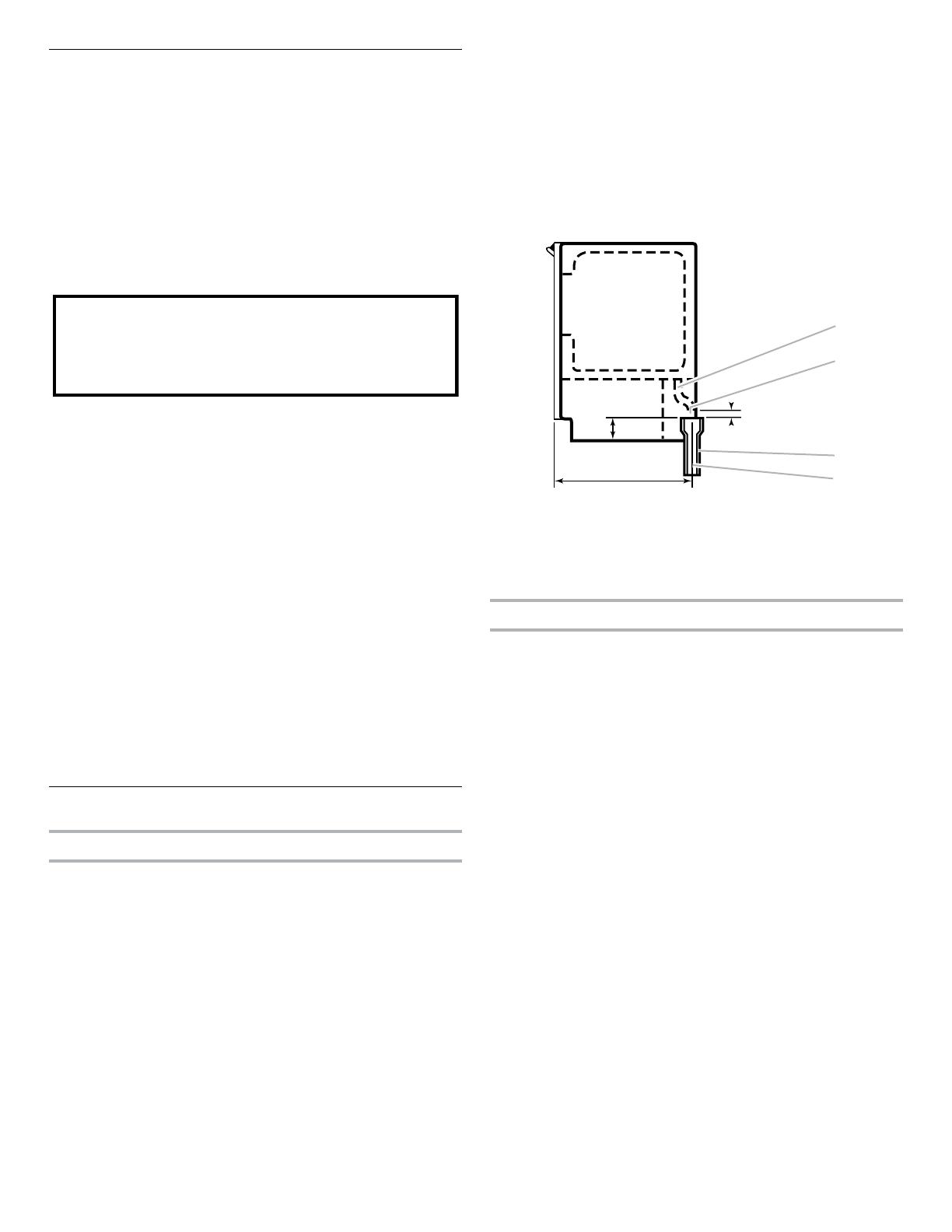
The ideal installation has a standpipe with a 1¹⁄
2
" (3.81 cm) to
2" (5.08 cm) PVC drain reducer installed directly below the
outlet of the drain tube as shown. You must maintain a 1"
(2.54 cm) air gap between the drain hose and the standpipe.
Do not connect the outlet end of the drain tube to a closed
pipe system to keep drain water from backing up into the ice
maker.
IMPORTANT: A drain pump is necessary when a oor drain is not
available. A Drain Pump kit, Part Number 1901A, is available for
purchase.
Side View
Drain Pump System (on some models)
IMPORTANT:
Connect the ice maker drain to your drain in accordance with
the International Plumbing Code and any local codes and
ordinances.
The drain pump discharge line must terminate at an
open-site drain.
Maximum rise 10 ft (3.1 m)
Maximum run 100 ft (30.5 m)
NOTES:
If the drain hose becomes twisted and water cannot drain,
your ice maker will not work.
It may be desirable to insulate the drain line thoroughly
up to the drain inlet. An Insulation Sleeve kit, Part Number
W10365792, is available for purchase.
Do not connect the outlet end of the drain tube to a closed
pipe system to keep drain water from backing up into the ice
maker.
Drain pump maximum capability: For every 1 ft (0.31 m) of
rise, subtract 10 ft (3.1 m) of maximum allowable run.
Do not use with water that is microbiologically unsafe or
of unknown quality without adequate disinfection before
or after the system. Systems certified for cyst reduction
may be used on disinfected waters that may contain
filterable cysts.
A
D
C
B
A. Drain hose
B. 1" (2.54 cm) air gap
C. PVC drain reducer
2"-1½" (5 cm - 3.8 cm)
D. Center of drain should be 23" (58.4 cm) from
front of door, with or without the 3/4"
(1.91 cm) panel on the door. The drain should
also be centered from left to right (7
5
/
16
"
[18.56 cm] from either side of the ice maker).
1
7
/
8
"
(4.8 cm)
23"
(58.4 cm)
1" (2.54 cm)
5
Door Reversal
1. Unplug the ice maker or disconnect power.
2. Remove the screws attaching top and bottom hinge covers
using an 3/16" hex driver.
3. Using pliers, remove the hinge covers from the top and
bottom hinges.
NOTE: Save the hinge covers for future use. Reinstall the
hinge covers if product is removed from cabinet installation.
4. Lay down the ice maker as shown in the illustration. Be sure
to cover the oor with cardboard or hardboard to avoid
damaging it.
5. Remove the screws holding the stainless steel panel from the
bottom of the door. Set the stainless steel panel and screws
aside. For custom panel model, Remove the screws and the
top metal bracket using the Phillips screwdriver.
Place them aside.
6. Remove the plastic screw cover from the inside of the hinges
and set aside.
7. Remove the top and bottom plastic end caps from the door.
WARNING
Electrical Shock Hazard
Disconnect power before servicing.
Replace all parts and panels before operating.
Failure to do so can result in death or electrical shock.
Crush Hazard
Articulated hinges are self closing and many pinch
points exist prior to cabinet installation.
Do not remove hinge covers until product is ready to
be installed.
Failure to follow these instructions can result in crush,
cut, or pinch injuries.
WARNING
A
A. Hinge cover
6
8. Unscrew the door hinge screws completely from top and
bottom hinges and place them aside.
9. Remove the door and place it aside. Swap the hinge screws
to the opposite side.
10. Remove the screws and hinges from the cabinet with the
Torx T25 screwdriver and place them aside.
11. Remove the screw cap cover and replace on the other side.
Preparing the Bottom Hinges
1. Unscrew and remove the grill cover using a Torx T20
screwdriver. Place them aside.
2. Remove the screw cover and place it on the other side as
shown in the illustration.
3. Reinstall the grill cover.
Crush Hazard
Articulated hinges are self closing and many pinch
points exist prior to cabinet installation.
Do not operate, or close, the hinges while they are
removed from the ice maker.
Failure to follow these instructions can result in crush,
cut, or pinch injuries.
WARNING
A
A. Grill cover screws
Torx,T20 and T25 are trademarks of Acument Intellectual Properties, LLC.
7
Reversing the Hinges and End Caps
1. Install the hinge screws (placed aside in step 10 of “Door
Panel and Hinge Removal”) half way on the desired side of the
cabinet.
2. Take the original top hinge, ip it and place it in the bottom
hinge position on the opposite side. Slide onto the cabinet
hinge screws. The hinge tabs on the hinges should always
face towards each other.
3. Take the original bottom hinge, ip it and place it in the top
hinge position on the opposite side. Slide onto the cabinet
hinge screws.
4. Fully tighten the top and bottom hinge screws.
Final Door Placement
NOTE: Before placing the door back on the ice maker, check all
installed parts to ensure there are no exposed screws, all screw
cover caps are on, and the door is facing the correct way with the
stainless steel door facing out.
1. Slide the door onto the hinges. Using Torx T25 screwdriver
install the screws (removed in the step 6 of “Removing the
Hinges” section) onto the door.
2. Reinstall the plastic screw cover to original locations on the
hinges.
3. Reinstall the top and bottom end caps on the door (the top
right end cap is now the bottom left end cap and vice versa).
NOTE: For custom wood install skip this step.
4. Place the steel door panel back on the door once all screws
are tightened. For custom door panel, skip this step.
A
A. Hinge tab
8
5. Screw the two hex heads screws back in at the bottom of the
door. For custom door panel, skip this step.
6. Return the ice maker back to upright position.
Reverse Door Catch
1. Remove the white decorative screws from the opposite side
of the door and set aside.
2. Remove the screws from the magnetic door catch and place
them on the opposite side of the door.
3. Install the white decorative screws on the opposite side of the
door.
4. Plug into a grounded 3 prong outlet.
Drain Pump Installation
(on some models)
NOTES:
Connect drain pump to your drain in accordance with all state
and local codes and ordinances.
It may be desirable to insulate drain tube thoroughly up
to drain inlet to minimize condensation on the drain tube.
Insulated tube kit Part Number W10365792 is available for
purchase.
Drain pump is designed to pump water to a maximum height
of 10 ft (3 m). Use only Whirlpool approved drain pump kit
Part Number 1901A.
Do not connect the outlet end of the drain tube to a closed
pipe system to keep drain water from backing up into the ice
maker.
Kit Contains:
Drain pump kit Part Number 1901A
5/8" I.D. x 5
1
/
8
" drain tube (ice maker bin to drain pump
reservoir inlet)
1/2" I.D. x 10 ft (3 m) drain tube hose (drain pump discharge
to household drain)
5/16" I.D. x 32" (81 cm) vent tube (drain pump reservoir vent
to ice maker cabinet back)
Cable tie (secures vent tube to back of ice maker) (1)
#8-32 x 3/8" pump mounting screws (secures drain pump to
baseplate and clamps to back of ice maker) (5)
5/8" small adjustable hose clamp (secures vent to drain
pump)
7/8" large adjustable hose clamp, (secures drain tube to ice
maker bin and drain pump reservoir inlet) (3)
Rear panel (2)
Instruction sheet
Electrical Shock Hazard
Plug into a grounded 3 prong outlet.
Do not remove ground prong.
Do not use an adapter.
Do not use an extension cord.
Failure to follow these instructions can result in death,
fire, or electrical shock.
WARNING
9
If Ice Maker Is Currently Installed
NOTE: If ice maker is not installed, please proceed to “Drain
Pump Installation” section.
1. Push the selector switch to the OFF position.
2. Unplug ice maker or disconnect power.
3. Turn off water supply. Wait 5 to 10 minutes for the ice to fall
into the storage bin. Remove all ice from bin.
4. Unscrew the drain cap from the bottom of the water
pan located inside the storage bin. Allow water to drain
completely. Replace drain cap. See “Drain Cap” illustration.
Drain Cap
5. If ice maker is built into cabinets, pull ice maker out of the
opening.
6. Disconnect water supply line. See “Water Supply Line”
illustration.
Water Supply Line
Drain Pump Installation
NOTE: Do not kink, smash or damage tubes or wires during
installation.
1. Unplug ice maker or disconnect power.
2. Remove rear panel. See “Rear Panel” illustration for screw
locations. Pull rear panel away from the drain tube. For
standard model discard the rear panel. For Custom panel
model, set aside the rear panel (it will be reused in step 17).
Rear Panel
3. Remove the old drain tube and clamp attached to the ice
maker bin.
NOTE: Discard old drain tube and clamp.
4. Slide drain pump into the ice maker base on the right side.
The pump mounting tab should slip into the rectangular slot
in the ice maker base. It will be necessary to tip the pump
slightly to slip into the slot. See “Drain Pump Mounting Tab
Slot” illustration.
Drain Pump Mounting Tab Slot
Drain Pump Installed
WARNING
Electrical Shock Hazard
Disconnect power before servicing.
Replace all parts and panels before operating.
Failure to do so can result in death or electrical shock.
A
A. Drain cap
A
C
B
B
C
D
E
A. 1/4" copper tubing
B. Cable clamp
C. 1/4" compression nut
D. Ferrule (sleeve)
E. Ice maker connection
A
A
A. Screw locations for standard model
B. Screw locations for custom panel model
B
A
A. Mounting tab slot
A
A. Drain pump installed
10
5. Align the 2 screw holes at the rear of the pump. Use two
#8-32 x 3/8" screws, supplied. See “Parts Locations”
illustration.
6. Install vent tube (5/16" I.D. x 32" [81 cm]) to drain pump
reservoir vent behind the wiring cover. Use supplied 5/8" small
adjustable clamps. See “Parts Locations” illustration. Use
plastic retainer to keep vent hose secure to top of inner deck.
NOTE: Do not install household drain tube this time.
Parts Locations
7. Remove wiring cover. Refer following illustration for location of
the screws.
8. Route vent tube through plastic retainer that is located
underneath top deck in open pump area as shown in
illustration. Using cable tie, tie the vent tube to the black
suction tube which is located behind the wiring cover. Refer
"Vent Tube" illustration.
Vent Tube
NOTE: Do not pinch, kink or damage the vent tube. Check that it
is not damaged or pinched or kinked between the cabinet and the
ice maker.
9. Secure wiring cover back in place.
10. Remove power cord clamp and ground screw attached to ice
maker power cord, which is mounted to the unit base. See
“Parts Locations” illustration.
NOTE: Clamp and screw will be reused.
11. Coil ice maker power cord into a 4" (10.2 cm) diameter
coil. Wrap electrical tape around the power cord in several
places to keep the cord in a coil. Locate coiled power cord
between the drain pump and side of enclosure and plug into
the receptacle of the drain pump. See “Parts Locations”
illustration.
12. Attach the drain pump power cord to ice maker unit base with
clamp and screw (removed in Step 6) that was used to attach
ice maker power cord. See “Parts Locations” illustration.
13. Install new drain tube (5/8" I.D. x 5¹⁄
8
") from ice maker bin to
drain pump reservoir inlet using new adjustable clamps. See
“Drain Tube” illustration.
NOTES:
Do not kink.
Trim tube length if required.
Drain Tube
C
H
I
G
F
E
D
B
A
A. Vent tube
B. 5/8" hose clamp
C. Drain pump discharge tube
D. Drain pump
E. Ice maker unit power cord
F. #8-32 x 3/8" pump mounting
screws
G. Drain pump power cord,
clamp and screw
H. Plastic retainer
I. Wiring cover
A
B
A. Wiring cover
B. Screws
A. Vent tube
B. Cable ties
C. Plastic retainer
A
B
C
A
B
C
D
A. 7/8" adjustable hose clamp
B. Drain tube (ice bin to drain pump)
C. 7/8" adjustable hose clamp
D. Drain pump reservoir inlet
11
14. Attach 1/2" I.D. x 10 ft (3 m) drain tube to pump discharge
tube. See “Parts Locations” illustration.
NOTE: Do not connect outlet end of drain tube to a closed
pipe system to keep drain water from backing up into the ice
maker.
For standard model, skip to step 17.
15. Install the cable tie on the rear panel using two holes provided
on the rear panel.
16. Using a cable tie, x the drain tube to rear panel.
17. For standard model, place new rear panel (small one for 15"
ice makers, large one for 18") against the back of the ice
maker. For custom panel model, reuse the plastic rear panel
(removed in step 2). Route the vent tube and drain pump
discharge tube through cutouts in the rear panel.
18. Secure rear panel with original screws. See “Rear Panel”
illustration.
19. Check all connections for leaks.
Connect Water Supply
Read all directions before you begin.
IMPORTANT:
Connect to potable water only.
Plumbing shall be installed in accordance with the
International Plumbing Code and any local codes and
ordinances.
Use copper tubing or Whirlpool supply line, Part Number
8212547RP, and check for leaks.
Install tubing only in areas where temperatures will remain
above freezing.
Tools Needed:
Gather the required tools and parts before starting installation:
7/16" and 1/2" open-end wrenches or two adjustable
wrenches
NOTE: Do not use a piercing-type or 3/16" (4.76 mm) saddle
valve which reduces water ow and clogs more easily.
Connecting the Water Line
1. Turn off main water supply. Turn on nearest faucet long
enough to clear line of water.
2. Using a 1/2" copper supply line with a quarter-turn shutoff
valve or the equivalent, connect the ice maker as shown.
NOTE: To allow sufcient water ow to the ice maker a
minimum 1/2" diameter home supply line is recommended.
3. Now you are ready to connect the copper tubing. Use 1/4"
(6.35 mm) O.D. soft copper tubing for the cold water supply.
Ensure that you have the proper length needed for the job.
Be sure both ends of the copper tubing are cut square.
Slip compression sleeve and compression nut on copper
tubing as shown. Insert end of tubing into outlet end
squarely as far as it will go. Screw compression nut onto
outlet end with adjustable wrench. Do not overtighten.
For custom panel install, be sure there water line extends
30" beyond the cabinet for future servicing purpose
4. Place the free end of the tubing into a container or sink, and
turn on main water supply and ush out tubing until water is
clear. Turn off shutoff valve on the water pipe.
IMPORTANT: Always drain the water line before making
the nal connection to the inlet of the water valve to avoid
possible water valve malfunction.
A
A. Holes to x the cable tie
Do not use with water that is microbiologically unsafe or
of unknown quality without adequate disinfection before
or after the system. Systems certified for cyst reduction
may be used on disinfected waters that may contain
filterable cysts.
A
B
A. Bulb
B. Nut
B
C
A
A. Compression sleeve
B. Compression nut
C. Copper tubing
12
5. Water inlet tube is located on the rear side of the ice maker as
shown in "Rear View" illustration. Bend the copper tubing to
match with water line inlet. Leave the coil of copper tubing as
it is to allow the ice maker to be pulled out of the cabinet or
away from the wall for service.
Rear View
6. Remove and discard the short, plastic tube from the end of
the water line inlet.
7. Thread the nut onto the end of the tubing. Tighten the nut by
hand. Then tighten it with a wrench two more turns. Do not
overtighten.
NOTE: To avoid rattling, be sure the copper tubing does not
touch the cabinet’s side wall or other parts inside the cabinet.
8. Install the water supply tube clamp around the water supply
line to reduce strain on the coupling. For custom panel
models, skip this step.
9. Turn shutoff valve ON.
10. Check for leaks. Tighten any connections (including
connections at the valve) or nuts that leak.
Leveling and Securing
It is important for the ice maker to be level in order to work
properly. Depending upon where you install the ice maker, you
may need to make several adjustments to level it. You may also
use the leveling legs to lower the height of the ice maker for
undercounter installations.
Tools Needed
Gather the required tools and parts before starting installation.
Level
Adjustable wrench
NOTE: It is easier to adjust the leveling legs if you have another
person to assist you.
1. Move the ice maker in front of its nal location. Be sure
to cover the oor with cardboard or hardboard to avoid
damaging it.
NOTE: If this is a built-in installation, move the ice maker as
close as possible to the nal location.
2. Remove the screws attaching top and bottom hinge covers
using an 3/16" hex driver.
A
C
B
A. Copper tubing
B. Water supply tube clamp
C. Inlet water tube clamp and
supply line connector for
standard model
D. Inlet water tube for custom
panel model
D
DAB C
A. Line to ice maker
B. Compression nut
C. Compression sleeve
D. Supplied line from ice maker
WARNING
Excessive Weight Hazard
Use two or more people to move and install ice maker.
Failure to do so can result in back or other injury.
Crush Hazard
Articulated hinges are self closing and many pinch
points exist prior to cabinet installation.
Do not remove hinge covers until product is ready to
be installed.
Failure to follow these instructions can result in crush,
cut, or pinch injuries.
WARNING
A
A. Hinge cover
13
3. Using pliers, remove the hinge covers from the top and
bottom hinges.
NOTE: Save the hinge covers for future use. Reinstall the
hinge covers if product is removed from cabinet installation.
4. For custom panel installation, install the door panel according
to the instructions in the “Custom Wood Panel” section.
5. Use ice maker leveling legs to align ice maker door to the
adjacent cabinet opening.
6. Slide ice maker into the cabinet while managing the utility
connection positions behind the ice maker. Be sure to cover
the oor with cardboard or hardboard to avoid damaging it.
IMPORTANT: For the custom panel model ush install, the ice
maker utility connections must be routed out through the slot
in the ice maker rear panel. Any time ice maker is removed for
service, do the same process when placing the unit back in
the cabinets.
7. Be sure that the ice maker is at desired depth. Secure the top
and bottom hinges to the side of the cabinet using wood
screws.
8. Attach the cabinet brackets (provided with ice maker) to the
holes in the front of ice maker as shown in the illustration.
Attach the cabinet brackets to the side of the cabinet with
wood screws.
NOTE: For the custom wood panel installation, continue
installation at step 7 of “Custom wood panel installation.”
WARNING
Excessive Weight Hazard
Use two or more people to move and install ice maker.
Failure to do so can result in back or other injury.
A
A. Cabinet bracket
14
Custom Wood Panel
Custom Panel Dimensions
If you plan to install a custom overlay panel, you will need to
make the panel yourself or consult qualied cabinetmaker or
carpenter
IMPORTANT:
The thickness of overlay panel must be 3/4" (1.91 cm).
Overlay panel must not weigh more than 8lbs (3.62 kg).
Overlay panels weighing more than recommended may cause
damage to your ice maker.
Match wood grain direction with that of adjacent cabinets.
Sand panel edges to provide a smooth nish.
Use moisture sealer on both sides and all edges of the panel
to avoid damage from outside.
Option 1 - Without Hinge-Side Spacer
To allow proper clearance for the door, prepare the custom
overlay panel using the dimension shown.
Option 2 - With Hinge-Side Spacer
To achieve a ush installation with adjacent cabinets, prepare the
custom overlay panel using the dimensions shown.
Top of Panel
Bottom of Panel
14¹⁷⁄₃₂"
(36.9 cm)
29¹⁄₂"
(74.9 cm)
1
¹⁄₄
"
(3.18 cm)
1
¹⁄₄
"
(3.18 cm)
1/4"
(6.35 mm)
1/4"
(6.35 mm)
3/4"
(1.91 mm)
3/4"
(1.91 mm)
14⁵⁄₈"
(37.1 cm)
29¹⁄₂"
(74.9 cm)
B
A
A. Front-visible surface when installed
B. Hinge Side
B
A
A. Front-visible surface when installed
B. Hinge Side
15
Custom Panel Installation
1. Remove screws and the top metal bracket using the Phillips
screwdriver. Remove and place them aside. Skip this step and
go to the step 4 if the door reversal has been completed.
2. Remove the top and bottom end caps using the Phillips
screwdriver and place them aside.
3. Reinstall top metal bracket using screws removed in the
step 1.
4. Lightly press the custom panel onto the door using double
sided adhesive tape. Adjust height of the panel to align with
the adjacent cabinetry. Press the panel rmly against door.
5. From inside the door, install the wood screws through the
slotted holes in the metal brackets.
Continue to “Leveling and Securing” section at step 5.
6. Adjust the panel side to side to achieve a desired gap on both
sides. Install the remaining screws through the door bracket
into the panel.
NOTE: Be sure that the panel is aligned with adjacent cabinet
before installing the remaining screws to secure the door
panel.
7. Replace the top and bottom end caps into the door. Fix the
bottom end cap using screw through the bottom metal
bracket hole.
16
Connecting the Drain
After ensuring that the drain system is adequate, follow these
steps to properly place the ice maker:
1. Style 1—For a gravity drain system, be sure that the ice
maker drain tube is positioned over the PVC drain reducer.
See the “Gravity Drain System” section.
Style 2—For a drain pump system, connect the drain
pump outlet hose to the drain. Refer the “Drain Supply
Requirements” section.
NOTE: Do not connect outlet end of drain tube to a closed
pipe system to avoid drain water from backing up into the ice
maker.
2. Plug in ice maker or reconnect power.
3. Turn on ice maker. Wait for rinsing cycle, approximately
5 minutes, to be sure the ice maker is operating properly.
4. If it is required by your local sanitation code, seal the cabinet
to the oor with an approved caulking compound after all
water and electrical connections have been made.
Auxiliary Grill Installation
The auxiliary grill is an optional part that can be used to align
the toe grill with the rest of the cabinets (while not obstructing
ventilation of the ice maker).
Tools required:
Torx T20 screwdriver
1/8" straight drill bit and power drill
1. First, complete all installation steps and install leveled ice
maker into the cabinet. Ensure ice maker is ush with the
adjacent cabinets.
2. Unpack kit by removing outer cushion packaging and discard
packaging material.
3. Remove screws that are taped onto the inside of the auxiliary
grill.
4. Place grill onto cabinetry. Align part so that grating pattern on
the auxiliary grill matches that of the toe grill on the ice maker.
5. Center auxiliary grill on cut out for ice maker. Mark hole
locations on each side of auxiliary grill on cabinet.
6. Using power drill and a 1/8" drill bit, drill holes in cabinet. This
is to t screws of size 8-18 x 0.750.
7. Using the Torx T20 screwdriver, screw auxiliary grill into
cabinet.
NOTE: For future service of ice maker, auxiliary kit must be
removed prior to the removal of the ice maker from the cabinets.
WARNING
Excessive Weight Hazard
Use two or more people to move and install ice maker.
Failure to do so can result in back or other injury.
Electrical Shock Hazard
Plug into a grounded 3 prong outlet.
Do not remove ground prong.
Do not use an adapter.
Do not use an extension cord.
Failure to follow these instructions can result in death,
fire, or electrical shock.
WARNING
17
Deep Clean
Interior Components
1. Unplug ice maker or disconnect power.
2. Open the storage bin door and remove any ice that is in the
bin.
3. Remove the drain cap from the water pan and drain
thoroughly. Replace the drain cap securely on the water pan.
If the drain cap is loose, water will empty from the water pan,
and you will have either thin ice or no ice.
4. Pull out on the bottom of the cutter grid cover until the snaps
release to remove.
NOTE: On some models, remove the screw from the cutter
grid cover.
5. Unplug the wiring harness from the left side of the cutter grid.
6. Unplug the ice level sensor from the right side of the cutter
grid. Pull the ice level sensor down and forward away from the
cutter grid.
7. Remove the right-hand and left-hand screws. Lift the cutter
grid up and out.
NOTE: Make sure the plastic spacer from the right-hand side
of the cutter grid bracket stays with the cutter grid.
8. Remove the mounting screw that holds the water pan in
place. Pull out on the front of the water pan.
9. Disconnect the pump bracket from the water pan and unplug
the water pan drain pump.
10. Remove, clean and replace the ice scoop holder and ice
scoop.
NOTE: On some models, the ice scoop holder is located in
the upper left of the unit, and on other models, the ice scoop
holder is located in the lower left of the unit.
On Some Models
Remove the holder by removing the 2 screws.
Wash the ice scoop holder and ice scoop along with the
other interior components using the following instructions.
Replace the ice scoop holder by replacing the screws.
On Some Models
After removing the ice scoop, remove the holder by
removing the 2 screws.
NOTE: On some models, remove the holder by lifting up
on the ice scoop holder and then out.
A
B
A. Cutter grid cover
B. Screw (on some models)
A
A. Cutter grid cover
A
B
C
D
E
F
A. Cutter grid harness
B. Screw
C. Cutter grid
D. Ice level sensor harness
E. Plastic spacer
F. Screw
A
B
C
D
A. Water pan
B. Water pan screw
C. Drain cap
D. Drain pump cover
B
A
A. Screw
B. Ice scoop holder
18
Wash the ice scoop holder along with the other interior
components using the following instructions.
Replace the ice scoop holder by replacing the screws or
on some models, pushing in on the holder and then down.
11. Wash the interior components (cutter grid, exterior of hoses,
and water pan) and the storage bin, door gasket, ice scoop,
and ice scoop holder with mild soap or detergent and warm
water. Rinse in clean water. Then clean the same parts with a
solution of 1 tbs (15 mL) of household bleach in 1 gal. (3.8 L)
warm water. Rinse again thoroughly in clean water.
NOTE: Do not remove hoses. Do not wash plastic parts in
dishwasher. They cannot withstand temperatures above
145°F (63°C).
12. To replace the water pan, set the water pan inside the ice bin.
Hook up the water pan pump. Snap the pump bracket back
onto the water pan and place back into position. Secure the
water pan by replacing the mounting screw.
13. Check the following:
Drain cap from the water pan is securely in place. If the
drain cap is loose, water will empty from the water pan,
and you will have either thin ice or no ice.
Hose from water pan is inserted into storage bin drain
opening.
14. Slide the cutter grid back into place and secure it by replacing
the right-hand screw and plastic spacer. Then tighten the left-
hand screw. Reconnect the cutter grid harness and the ice
level sensor harness.
15. Replace the cutter grid cover.
NOTE: On some models, replace the cutter grid cover using
the screw removed earlier.
16. Gently wipe the control panel with a soft, clean dishcloth
using warm water and a mild liquid dish detergent.
17. Plug in ice maker or reconnect power.
18. After cleaning, make sure that all controls are set properly and
that no control indicators are ashing.
Quick Clean
You will need to use one 16-ounce (473 mL) bottle of approved
ice maker cleaner. We recommend using the *affresh
®
Ice
Machine Cleaner part number 4396808.
A
A. Ice scoop holder
*
affresh
®
is a registered trademark of Whirlpool, U.S.A.
19
SÉCURITÉ DE LA MACHINE À GLAÇONS
Risque possible de décès ou de blessure grave si vous ne
suivez pas immédiatement les instructions.
Risque possible de décès ou de blessure grave si vous
ne suivez pas les instructions.
Tous les messages de sécurité vous diront quel est le danger potentiel et vous disent comment réduire le risque de blessure et
ce qui peut se produire en cas de non-respect des instructions.
Votre sécurité et celle des autres est très importante.
Nous donnons de nombreux messages de sécurité importants dans ce manuel et sur votre appareil ménager. Assurez-vous de
toujours lire tous les messages de sécurité et de vous y conformer.
AVERTISSEMENT
DANGER
Voici le symbole d’alerte de sécurité.
Ce symbole d’alerte de sécurité vous signale les dangers potentiels de décès et de blessures graves à vous
et à d’autres.
Tous les messages de sécurité suivront le symbole d’alerte de sécurité et le mot “DANGER” ou
“AVERTISSEMENT”. Ces mots signifient :
IMPORTANTES INSTRUCTIONS DE SÉCURITÉ
AVERTISSEMENT :
Pour réduire le risque d'incendie, de choc électrique ou de blessures lors de l'utilisation de la
machine à glaçons, il convient d'observer certaines précautions élémentaires :
CONSERVEZ CES INSTRUCTIONS
Brancher sur une prise à 3 alvéoles reliée à la terre.
Ne pas enlever la broche de liaison à la terre.
Ne pas utiliser un adaptateur.
Ne pas utiliser un câble de rallonge.
Débrancher la source de courant électrique avant de
nettoyer manuellement les composants intérieurs.
Déconnecter la source de courant électrique avant
l'entretien.
Replacer pièces et panneaux avant de faire la remise en
marche.
Utiliser deux personnes ou plus pour déplacer et
installer la machine à glaçons.
20
INSTRUCTIONS D’INSTALLATION
Déballage de la machine à glaçons
Enlèvement des matériaux d’emballage
Enlever le ruban adhésif et la colle de la machine à glaçons avant
de l’utiliser.
Pour enlever tout résidu de ruban adhésif ou de colle de la
surface extérieure de la machine à glaçons, frotter vivement
la zone avec le pouce. Les résidus de ruban adhésif et de
colle peuvent aussi facilement être enlevés en frottant à l’aide
d’un doigt une petite quantité de savon liquide à vaisselle sur
l’adhésif. Rincer à l’eau tiède et sécher.
Ne pas utiliser d’instruments coupants, d’alcool à friction, de
liquides inammables ou de nettoyants abrasifs pour enlever
le ruban adhésif ou la colle. Ne pas utiliser d’eau de Javel sur
les surfaces en acier inoxydable de la machine à glaçons.
Cesproduits peuvent endommager la surface de votre
machine à glaçons.
Nettoyage avant utilisation
Après avoir enlevé tous les matériaux d’emballage, nettoyer
l’intérieur de la machine à glaçons avant de l’utiliser. Voir les
instructions de nettoyage à la section “Entretien de la machine
àglaçons” du Guide d’utilisation et d’entretien.
Vacances ou longue
période d’inutilisation
Lorsque la machine à glaçons n’est pas utilisée pendant une
longue période de temps, fermer l’alimentation en eau et en
électricité de la machine.
S’assurer que les tuyaux d’alimentation en eau sont isolés
contre le gel. La formation de glace dans les canalisations
d’arrivée d’eau peut entraîner une élévation de la pression
en eau et endommager la machine à glaçons ou le domicile.
La garantie de l’appareil ne couvre pas les dommages
imputables au gel.
Exigences d’emplacement
L’installation doit respecter les dispositions de tous les codes
et règlements en vigueur.
Pour assurer une bonne ventilation de votre machine à
glaçons, l’avant doit être entièrement dégagé. Les autres
côtés et le dessus de l’appareil peuvent être dissimulés, mais
l’installation doit permettre de tirer la machine à glaçons vers
l’avant pour y faire l’entretien requis.
L’ensemble de grilles auxiliaires inclus (seulement sur les
modèles avec panneau personnalisé) peut être utilisé pour
aligner la grille inférieure avec le reste des armoires sans
bloquer la ventilation de la machine à glaçons.
L’installation de la machine à glaçons requiert un tuyau
d’alimentation en eau en cuivre de 1/4 po (6,35mm) de
diamètre extérieur avec robinet d’arrêt ou la canalisation
d’alimentation de Whirlpool (numéro de pièce: 8212547RB)
etune pompe de vidange approuvée par Whirlpool (numéro
de pièce: 1901A) pour diriger l’eau vers un drain existant.
Choisir un endroit bien aéré où la température est supérieure
à 13°C (55°F) et inférieure à 43°C (110°F). Les meilleurs
résultats sont obtenus lorsque la température est comprise
entre 70°F et 90°F (21°C et 32°C).
La machine à glaçons doit être installée dans un endroit
protégé des éléments comme le vent, la pluie, les jets
d’eauou les renversements.
Lorsque l’appareil est installé sous un comptoir, observer
les dimensions d’ouverture recommandées. Positionner les
entrées électrique et d’eau aux emplacements recommandés.
REMARQUES:
Vérier que le cordon d’alimentation n’est pas
endommagé, déformé ou coincé entre la machine
àglaçons et la caisse de l’appareil.
Vérier que le tuyau d’entrée d’eau n’est pas endommagé,
déformé ou pincé entre la machine à glaçons et l’armoire.
Vérier que la canalisation d’évacuation (sur certains
modèles) n’est pas endommagée, déformée ou coincée
entre la machine à glaçons et la caisse de l’appareil.
Choisir un emplacement où le plancher est de niveau.
Lamachine à glaçon doit être de niveau pour fonctionner
correctement. Au besoin, il est possible de régler la hauteur
de la machine à glaçons en changeant la hauteur des pattes
de nivellement. Consulter la section “Mettre de niveau et
sécuriser”.
AVERTISSEMENT
Risque du poids excessif
Utiliser deux ou plus de personnes pour déplacer et
installer la machine à glaçons.
Le non-respect de cette instruction peut causer
une blessure au dos ou d'autre blessure.
1 / 1

KitchenAid KUIX335HBL00 Installation guide

Category
Barbecues & grills
Type
Installation guide

Ask a question and I''ll find the answer in the document

Finding information in a document is now easier with AI

Ask the document