Munters 190TGB-1034-L1604 Owner's manual
- Category
- Dehumidifiers
- Type
- Owner's manual

Originalinstructions
Usermanual
ML180,ML270,MLT350
Desiccantdehumidier
190TGB-1034-L1604©MuntersEuropeAB2016

Importantuserinformation
Intendeduse
Muntersdehumidiersareintendedtobeusedforthe
dehumidicationofair.Anyotheruseoftheunit,or
usewhichiscontrarytotheinstructionsgiveninthis
manual,cancausepersonalinjuryanddamagetotheunit
andotherproperty.
Nomodicationoftheunitisallowedwithoutprior
approvalbyMunters.Attachmentorinstallation
ofadditionaldevicesisonlyallowedafterwritten
agreementbyMunters.
Warranty
Thewarrantyperiodisvalidfromthedatetheunit
leftourfactory,unlessotherwisestatedinwriting.
Thewarrantyislimitedtoafreeexchangeofpartsor
componentswhichhavefailedasaresultofdefectsin
materialsorworkmanship.
Allwarrantyclaimsmustincludeproofthatthe
faulthasoccurredwithinthewarrantyperiodand
thattheunithasbeenusedinaccordancewiththe
specications.Allclaimsmustspecifytheunittypeand
fabricationnumber.Thisinformationisstampedonthe
identicationplate,seesectionMarking.
Itisaconditionofthewarrantythattheunitforthefull
warrantyperiodisservicedandmaintainedbyaqualied
MuntersengineerorMuntersapprovedengineer.
Accesstospecicandcalibratedtestequipmentis
necessary.Theserviceandmaintenancemustbe
documentedforthewarrantytobevalid.
AlwayscontactMuntersforserviceorrepair.Operating
faultscanoccuriftheunitismaintainedinsufcientlyor
incorrectly.
Safety
Informationaboutdangersareinthismanualindicated
bythecommonhazardsymbol:
W W
W
ARNING! ARNING!
ARNING!
Indicatesapossibledangerthatcanleadtopersonalinjury.
CA CA
CA
UTION! UTION!
UTION!
Indicatesapossibledangerthatcanleadtodamagetothe
unitorotherproperty,orcauseenvironmentaldamage.
NOTE!Highlightssupplementaryinformationforoptimal
useoftheunit.
ConformitywithDirectives
Thedehumidierisinconformitywiththeessential
safetyrequirementsoftheMachineryDirective
2006/42/EC,andinconformitywiththeprovisionsof
theEcodesignDirective(ErP)2009/125/EC,andof
theEMCDirective2004/108/EC.Thedehumidieris
manufacturedbyanorganizationcertiedaccordingto
ISO9001andISO14001.
Copyright
Thecontentsofthismanualcanbechangedwithout
priornotice.
NOTE!Thismanualcontainsinformationwhichis
protectedbycopyrightlaws.Itisnotallowedtoreproduceor
transmitanypartofthismanualwithoutwrittenconsentfrom
Munters.
Pleasesendanycommentsregardingthismanualto:
MuntersEuropeAB
TechnicalDocumentation
P.O.Box1150
SE-16426KISTASweden
e-mail:t-doc@munters.se
iiImportantuserinformation190TGB-1034-L1604

Tableofcontents
Importantuserinformation...............ii
Intendeduse...........................
ii
Warranty...............................
ii
Safety..................................
ii
ConformitywithDirectives............
ii
Copyright..............................
ii
Tableofcontents...........................iii
1Introduction.................................1
1.1Aboutthismanual.....................
1
1.2Unintendeduse........................
1
1.3Safetyandcautions...................
1
1.4Markings...............................
3
1.5Supervisionofoperation..............
3
1.6Faultindications.......................
3
2Dehumidierdesign.......................4
2.1Productdescription...................
4
2.2Functiondescription..................
4
2.3Maincomponents.....................
5
3Transport,inspectionandstorage.......6
3.1Transport..............................
6
3.2Inspectionofdelivery..................
6
3.3Storingtheequipment................
6
4Installation...................................7
4.1Safety..................................
7
4.2Siterequirements.....................
7
4.3Foundation............................
8
4.4Mirrorhandedductconnections......
8
4.5Ductinstallation.......................
9
4.5.1Generalrecommendations...
9
4.5.2Ductforoutdoorairinlet.......
12
4.5.3Ductforwetairoutlet...........
12
4.6Precautionarymeasuresforunitswith
LIdesiccantrotor......................
13
4.7Electricalconnections................
13
4.8Externalhumiditysensor.............
13
5Commissioning.............................15
5.1Pre-startchecks.......................
15
5.2Airowcheckandadjustment........
16
6Operation....................................17
6.1General................................
17
6.2Quickstop..............................
17
6.3Beforestarting.........................
17
6.4Operatorpanel........................
18
6.5RH98operatorpanel..................
19
6.6Operatingtheunit.....................
19
6.6.1Manualmode..................
19
6.6.2Automaticmode–humidity
sensorconnected..............
20
6.6.3Automaticmode-RH98.......
20
7Serviceandmaintenance.................21
7.1Safety..................................
21
7.2General................................
21
7.3Serviceoptions........................
21
7.4Extendedwarranty....................
22
7.5Cleaning...............................
22
7.6Serviceandmaintenanceschedule..
22
7.7Filterchange...........................
24
8Faulttracing.................................25
8.1General................................
25
8.2Safety..................................
25
8.3Faulttracinglist........................
26
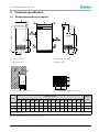
9Technicalspecication....................27
9.1Dimensionsandservicespace.......
27
9.2Capacitydiagrams....................
28
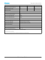
9.3Technicaldata.........................
29
9.4Sounddata.............................
31
9.4.1SounddataML180............
31
9.4.2SounddataML270............
32
9.4.3SounddataMLT350...........
32
10Scrapping....................................33
Appendix1Options.............................34
1.1General................................
34
1.2Runningtimemeter...................
34
1.3Humiditycontrolsystem..............
34
1.3.1Introduction....................
34
1.3.2Transmitter.....................
34
1.3.3Controlunit.....................
34
1.3.4Setpointsandcontrol
parameters.....................
35
1.3.5Display/changesetpointfor
relativehumidity...............
36
190TGB-1034-L1604Tableofcontentsiii


DehumidierML180-MLT350
1Introduction
1.1Aboutthismanual
Thismanualiswrittenfortheuserofthedehumidier.Itcontainsnecessaryinformationforhowtoinstall
andusethedehumidierinasafeandefcientway.Readthroughthemanualbeforethedehumidieris
installedandused.
ContactyournearestMuntersofceifyouhaveanyquestionsregardingtheinstallationortheuseofyour
dehumidier.
Thismanualmustbestoredinapermanentlocationclosetothedehumidier.
1.2Unintendeduse
■Thedehumidierisnotintendedforoutdoorinstallation.
■Thedehumidierisnotintendedforuseinclassiedareaswhereexplosionsafetycompliantequipment
isrequired.
■Thedehumidiermustnotbeinstallednearanyheatgeneratingdevicesthatcancausedamagetothe
equipment.
1.3Safetyandcautions
Everymeasurehasbeentakeninthedesignandmanufactureofthedehumidiertoensurethatitmeetsthe
safetyrequirementsofthedirectivesandstandardslistedintheECDeclarationofConformity.
Theinformationinthismanualshallinnowaytakeprecedenceoverindividualresponsibilitiesorlocal
regulations.
Duringoperationandotherworkwithamachineitisalwaystheresponsibilityoftheindividualtoconsider
thefollowing:
■Thesafetyofallpersonsconcerned.
■Thesafetyoftheunitandotherproperty.
■Theprotectionoftheenvironment.
ThetypesofdangersthatareindicatedinthismanualaredescribedinthesectionImportantuserinformation.
190TGB-1034-L1604Introduction1

DehumidierML180-MLT350
W W
W
ARNING! ARNING!
ARNING!
-Theunitmustnotbesplashedwithorimmersedinwater.
-Theunitmustneverbeconnectedtoavoltageorfrequencyotherthanthatforwhichitwasdesigned.Refertothe
identicationplate.Linevoltagethatistoohighcancauseanelectricalshockhazardanddamagetotheunit.
-Donotinsertngersoranyobjectsintotheairvents.
-Allelectricalinstallationsmustbecarriedoutbyaqualiedelectricianandinaccordancewithlocalregulations.
-Thedehumidiercanrestartautomaticallyafterapowercut.Alwayssetandlockthemainpowerswitchinthe
OFFpositionbeforecarryingoutanyservicework.
-Useonlyapprovedliftingequipmenttopreventpersonalinjuryanddamagetotheequipment.
-AlwayscontactMuntersforserviceorrepair.
2Introduction190TGB-1034-L1604

DehumidierML180-MLT350
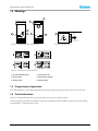
1.4Markings
(GB)CHANGE FILTER
(GB)CHANGE FILTER
1
2
3
4
5
6
6
Figure1.1Identicationplateandmarkings
(GB) CHANGE FILTER
(SW) BYT FILTER
(FR) REMPLACER LE FILTER
(DE) FILTER AUSWECHSELN
6
Figure1.2Replacelter
3
Figure1.3Labelsforairinletsandoutlets
1.Unitidenticationplate
4.Processairinlet
2.Dryairoutlet5.Reactivationairinlet
3.Wetairoutlet
6.Replacelter
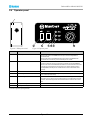
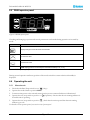
1.5Supervisionofoperation
Thedehumidieriscontrolledandmonitoredusingtheoperatorpanellocatedonthefrontoftheunit.
1.6Faultindications
Faultsareclearlyindicatedontheoperatorpanel,seesection6.4,Operatorpanel.
Alarmsrelatingtorelativeairhumidityaregiveninthedisplayofthehumiditycontrolsystem(ifinstalled),
seeappendix1.3,Humiditycontrolsystem.
190TGB-1034-L1604Introduction3

DehumidierML180-MLT350
2Dehumidierdesign
2.1Productdescription
ThedesiccantdehumidiersintheMLserieshavebeendevelopedtoeffectivelydehumidifytheairin
environmentsrequiringlowairhumidity.
Thedehumidierisequippedwithanencapsulatedrotorunit.Therotorcasingisconstructedofdurable
thermosetplasticandcontainsisolatedsectionsthatprovideaprecisebalanceforthedehumidication,
reactivationandheatrecoveryairows.
ThedehumidierismanufacturedinaccordancewithuniformEuropeanstandardsandestablished
requirementsforCE-marking.
2.2Functiondescription
1.Processair
2.Dryair
3.Reactivationair
2
4
3
1
Figure2.1Internalairows
4.Wetair
Thedesiccantrotoristheadsorptiondehumidifyingcomponentintheunit.Therotorstructureis
comprisedofalargenumberofsmallairchannels.
Thedesiccantrotorismadeofacompositematerialthatishighlyeffectiveinattractingandretainingwater
vapour.Therotorisdividedintwozones.Theairowtobedehumidied,processair,passesthroughthe
largestzoneoftherotorandthenleavestherotorasdryair.Sincetherotorrotatesslowly,theincomingair
alwaysmeetsadryzoneontherotor,thuscreatingacontinuousdehumidicationprocess.
Theairowthatisusedtodrytherotor,reactivationair,isheated.Thereactivationairpassesthrough
therotorintheoppositedirectiontotheprocessairandleavestherotoraswetair(warm,moistair).This
principleenablesthedehumidiertoworkeffectively,evenatfreezingtemperatures.
4Dehumidierdesign190TGB-1034-L1604

DehumidierML180-MLT350
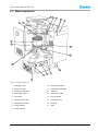
2.3Maincomponents
12
13
11
14
10
17
2
15
1
9
16
4
5
8
6
7
3
Figure2.2Maincomponents
1.
Sealingring,rotor
10.
Reactivationairlter
2.Upperrotorcover11.Reactivationairimpeller
3.Electricalcontrolpanel12.Fanmotor
4.Reactivationheater13.Processairimpeller
5.
Drivemotor14.
Processairlter
6.
Switch(rocker,2-pole)
15.Lowerrotorcover
7.
Temperatureindicator16.Drivebelt
8.Pulley,beltdrive17.Rotor
9.Roller,beltguide
190TGB-1034-L1604Dehumidierdesign5

DehumidierML180-MLT350
3Transport,inspectionandstorage
3.1Transport
Thedehumidierisdeliveredonapalletandmustbehandledcarefully.Allpaneldoorsontheunitmustbe
closedduringtransport.Providedthatthedehumidierisstillsecuredtoitsdeliverypallet,itcanbemoved
usingafork-lifttruck.
W W
W
ARNING! ARNING!
ARNING!
Movethedehumidiercarefullyasthereisariskofthedehumidiertippingover.
Figure3.1Correctlengthonforkliftarms
Weightofthedehumidiercanbefoundinsection9.1,Dimensionsandservicespace.
3.2Inspectionofdelivery
■Doaninspectionofthedeliveryandcomparewiththedeliverynote,orderconrmationorother
deliverydocumentation.Makesurethateverythingisincludedandnothingisdamaged.
■ContactMuntersimmediatelyifthedeliveryisnotcompleteordamagedinordertoavoidinstallation
delays.
■Removeallpackagingmaterialfromtheunit,andmakesurethatnodamagehasbeenmadeduring
transportation.
■AnyvisibledamagemustbereportedinwritingtoMunterswithin3daysandpriortoinstallationof
theunit.
■Discardthepackagingmaterialaccordingtolocalregulations.
3.3Storingtheequipment
Followtheseinstructionsifthedehumidieristobestoredpriortoinstallation:
■Placethedehumidierinanuprightpositiononahorizontalsurface.
■Re-usethepackagingmaterialtoprovideprotectionfortheunit.
■Protectthedehumidierfromphysicaldamage.
■Storethedehumidierundercoverandprotectitfromdust,frost,rainandaggressivecontaminants.
6Transport,inspectionandstorage190TGB-1034-L1604

DehumidierML180-MLT350
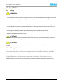
4Installation
4.1Safety
W W
W
ARNING! ARNING!
ARNING!
-Theunitmustnotbesplashedwithorimmersedinwater.
-Theunitmustneverbeconnectedtoavoltageorfrequencyotherthanthatforwhichitwasdesigned.Refertothe
identicationplate.Linevoltagethatistoohighcancauseanelectricalshockhazardanddamagetotheunit.
-Donotinsertngersoranyobjectsintotheairvents.
-Allelectricalinstallationsmustbecarriedoutbyaqualiedelectricianandinaccordancewithlocalregulations.
-Thedehumidiercanrestartautomaticallyafterapowercut.Alwayssetandlockthemainpowerswitchinthe
OFFpositionbeforecarryingoutanyservicework.
-Useonlyapprovedliftingequipmenttopreventpersonalinjuryanddamagetotheequipment.
-AlwayscontactMuntersforserviceorrepair.
CA CA
CA
UTION! UTION!
UTION!
Thewetairductmustalwaysbeinsulatedwhenthereisariskoffreezing.Condensationbuildsupeasilyonthe
insideoftheductbecauseofthehighmoisturecontentofthewetairleavingthedehumidier.
CA CA
CA
UTION! UTION!
UTION!
Thedehumidierhasbeendesignedtooperateatspecicprocessairowscorrespondingtothefansizes
installed.
4.2Siterequirements
Thedehumidierisonlyintendedforindoorinstallation.Avoidinstallingthedehumidierinadamp
environmentwherethereisariskofwaterenteringtheunitorinaverydustyenvironment.Ifindoubt,
contactMunters.Itisimportantthattheintendedinstallationsitemeetsthelocationandspacerequirements
fortheequipmentinordertoachievethebestpossibleperformance.
Fortheunitdimensionsandservicespacerequirements,seesection9.1,Dimensionsandservicespace.
NOTE!Ifthereisaneedforreductionofvibrationsfromthedehumidier,contactMuntersforinstructions.
190TGB-1034-L1604Installation7

DehumidierML180-MLT350
4.3Foundation
Thedehumidiermustbeinstalledonaleveloor,oronaplatformcapableofsupportingthemachine
weight.Ifthemaximumoorloadingweightisnotexceeded,specialfoundationsarenotrequired.
Whenthedehumidierhasbeeninstalled,checkthatitislevel.
Iflocalregulationsrequirethattheunitispermanentlyxedinposition,thexingholescanbeusedfor
boltingtheunittotheoor.
Figure4.1Drillingpattern
4.4Mirrorhandedductconnections
Thefrontandrearpanelsareinterchangeable,sothattheconnectionsforprocessairanddryairmaybe
situatedeitherontheleftorrightsideoftheunit.
Thedehumidiersaredeliveredwiththeprocessanddryairconnectionsontheleftsideoftheunit.If
itisrequiredtochangetheorientation,sothattheconnectionsareontherightsideoftheunit,proceed
asfollows.
W W
W
ARNING! ARNING!
ARNING!
Makesurethatthedehumidierisdisconnectedfromthemainspowerbeforechangingthepositionsofthe
processairanddryairconnections.
8Installation190TGB-1034-L1604

DehumidierML180-MLT350
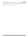
Figure4.2Changingpanelpositions
1.Removethetwobolts(B)securingthefrontpanelandcarefullyremovethepanel.
2.Removethetwoboltssecuringtherearpanelandcarefullyremovethepanel.
3.Removethetwobolts(A)andwasherssecuringthecontrolandtoppanels,thencarefullyremovethe
toppanel.
4.Removethecableductcovers(C),re-routethecablesandtthecontrolpanel(D)ontotheoppositeside
oftheunit.Retthecableductcovers.
5.Fitthefront,rearandtoppanelsintheirnewpositions.
4.5Ductinstallation
4.5.1Generalrecommendations
Theconnectionsforprocessandreactivationairaredesignedinaccordancewiththerecommendationsin
ISO13351.TherectangularductconnectionscontaintappedinsertsforM8screws.
Figure4.3Ductconnections
190TGB-1034-L1604Installation9

DehumidierML180-MLT350
Partnumber170-013477–001170-013477–002170-013477–003170-013477–004
A
Ø80Ø100Ø125Ø160
B
See9.1,Dimensionsandservicespace.
L(mm)
225225220140
ML180XX
ML270XX
MLT350XX
CA CA
CA
UTION! UTION!
UTION!
Thedehumidierhasbeendesignedtooperateatspecicprocessairowscorrespondingtothefansizes
installed.
■Theprocessairanddryairductsshouldbethesamediameter.Thesameappliestothereactivationair
andwetairducts.
■Thelengthofductworkmustbekeptasshortaspossibletominimisestaticairpressurelosses.
■Tomaintainperformance,allrigidprocessorreactivationairductworkjointsmustbeairandvapour
tight.
■Theprocessairductworkmustbeinsulatedtopreventcondensationdevelopingontheoutsideofthe
duct,wheneverthetemperatureoftheairwithintheductfallsbelowthedewpointtemperatureofthe
ambientairthroughwhichtheductworkisrouted.
■Theductsmustalwaysbeinsulatedwhenthereisariskoffreezing.
■Thewetairleavingthedehumidierwill,becauseofhighmoisturecontent,condenseontheinsideduct
walls.Byinsulatingtheducts,theamountofcondensateisreduced.
■Horizontalwetairductsmustbeinstalledwithaslightdecline(awayfromthedehumidier)todrain
awaypossiblecondensation.Suitablecondensationdrainsmustbeinstalledatlowpointsinthewet
airoutletduct,seeFigure4.6.
■Ensurethataccessforoperationandservicingisnotrestrictedwhendesigningandinstallingducting.
Formoreinformation,refertosection9.1,Dimensionsandservicespace.
■Toreducenoiseand/orvibrationbeingtransmittedalongrigidducts,goodquality,airtightexible
connectionscanbetted.
■Ductsmounteddirectlyontotheunitmustbeindependentlysupportedtominimisetheloadontheunit.
■Dampersforadjustingtheairowsmustbeinstalledinthesupplyairoutletandreactivationairinlet
ducts.Correctairowsareessentialfortheoperatingefciencyoftheunit.Forairowadjustment
instructions,seesection5.2,Airowcheckandadjustment.
■Thetotalpressuredropintheprocessandreactivationductworkmustnotexceedtheavailablepressure
ofthefansttedtothedehumidier.Fordetailsofminimumavailablestaticpressure,seesection
9.3,Technicaldata.
10Installation190TGB-1034-L1604

DehumidierML180-MLT350
ML
Munter s
420
1
2
3
5
5
4
C
B
D
A
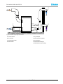
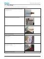
Figure4.4Ductsrequiredforinstallation
A.Processairinlet1.Dryairdamper
B.Dryairoutlet
2.Externallterbox(option)
C.Reactivationairinlet
3.Ducttransition
D.Wetairoutlet4.Reactivationairdamper
5.Outlet/inletduct(wirenetting)
190TGB-1034-L1604Installation11

DehumidierML180-MLT350
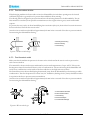
4.5.2Ductforoutdoorairinlet
Whenbringingambientairfromoutdoorsintothedehumidier,theinletductopeningmustbelocated
sufcientlyhighabovegroundleveltopreventdustanddebrisfromentering.
Theductingmustbedesignedtopreventrainandsnowfrombeingdrawnintothedehumidier.Theair
inletmustbelocatedawayfrompossiblecontaminantssuchasengineexhaustgases,steamandharmful
vapours.
Topreventthewet(outlet)airfromhumidifyingthereactivation(inlet)air,theairinletforreactivationmust
belocatedatleast2mfromthewetairoutlet.
Attachawirenetwithameshwidthofapproximately10mmintheouterendoftheducttopreventanimals
fromenteringthedehumidierducting.
Figure4.5Outdoorairinletdesign
A.Rectangularducting
B.Roundducting
C.Wirenetting
4.5.3Ductforwetairoutlet
Makesurethattheambientairpressureisthesameattheairinletandatthewetairoutlettopreventthe
riskofreverseairow.
Thematerialforthewetairductmustwithstandcorrosionandtemperaturesofupto100°C.Thewetair
ductingmustalwaysbeinsulatedifthereisariskofcondensation.Thewetairleavingthedehumidierwill
easilycausecondensationontheinsideoftheductwallsduetothehighmoisturecontent.
Horizontalductsmustbeinstalledslopingdownwards(awayfromthedehumidier)todrainawaypossible
condensation.Theductslopemustbeatleast2cm/m.Inaddition,drainageholes(5mm)shouldbemadeat
lowpointsintheducttopreventwateraccumulation.
Attachawirenetwithameshwidthofapproximately10mmintheouterendoftheducttopreventanimals
fromenteringthedehumidierducting.
Figure4.6Wetairoutletdesign
A.Horizontalwetairoutlet
B.Verticalwetairoutlet
C.Wirenetting
D.Downwardslope
E.Condensatedrainage
12Installation190TGB-1034-L1604

DehumidierML180-MLT350
4.6PrecautionarymeasuresforunitswithLIdesiccantrotor
ThestandarddeliveryisMuntershighperformancedesiccantrotorHPS(HighPerformanceSilicagel).
IfthedehumidierisdeliveredwithanLIrotor(lithiumchloride)itisimportantthattherotordoesnot
becomeloadedwithmoisturewhenthedehumidierisoff.
NOTE!Makesurethatnoairpassingthroughtherotorhasarelativehumiditygreaterthan80%.
Itisrecommendedtoinstallclosingdampersintheprocessandreactivationairinletstoavoidthatairwith
highrelativehumidityisdrawnthroughtherotorandintotheroom.
Thisisparticularlyimportantwhentheprocessairisdrawnfromoutdoors,orwhenthesystemhasbeen
ttedwithapre-cooler.
4.7Electricalconnections
W W
W
ARNING! ARNING!
ARNING!
Allelectricalequipmentconnectionsmustbecarriedoutinaccordancewithlocalregulationsandbyqualied
personnel.Riskofelectricalshock.
W W
W
ARNING! ARNING!
ARNING!
Theunitmustneverbeconnectedtoavoltageorfrequencyotherthanthatforwhichitwasdesigned.Refertothe
unitidenticationplate.
Eachunitissuppliedcompletewithalltheinternalwiringinstalledandconguredinaccordancewiththe
speciedvoltageandfrequencyontheidenticationplate.
ML180&MLT350dehumidiersaresuppliedcompletewithaprewiredmainscable.Thecableisttedwith
amulti-pinplugsuitableforconnectiontoasinglephaseearthedmainssocket.
NOTE!Thesupplyvoltagemustnotdifferfromthespeciedoperatingvoltagebymorethan+/-10%.
Forconnectiondetails,seetheidenticationplateandthewiringdiagramorsection9.3,Technicaldata.
4.8Externalhumiditysensor
ML-seriesdehumidiersarewiredsothatwhentheunitissettoAUTOmatic,itcanbecontrolledfrom
anexternallymountedhumiditysensor.
ML180-MLT350havebeendesignedwithaone-stepheater,andthereforecontrolislimitedtoswitchingthe
unitonandoffusingaone-stephumiditysensor.
Alowvoltageconnector(mountedonthesideoftheunit)isprovidedforelectricalconnectionofaone-step
humiditysensor.Formoreinformation,seethewiringdiagram.
NOTE!Wherenohumiditysensorisconnectedtotheunit,thedehumidierwillbeoperatingatmaximumoutput
foraslongastheunitisswitchedon.
Aroomhumiditysensoristobemounted1-1.5mabovetheoor.Itmustbepositionedsothatitisnot
directlyexposedtodryairfromtheunitortohumidairowinginthroughopeningdoors.Positionitaway
fromheatsourcesanddirectsunlight.
■Thehumiditysensorconnectingcableshouldhaveaconductorareaofnotlessthan
0,75mm
2
andmusthaveaninsulationresistanceratinginexcessof500VAC.
190TGB-1034-L1604Installation13

DehumidierML180-MLT350
■ThehumiditysensormustbedesignedsothatthecontactscloseonarisingRHtocompletethecontrol
circuitandstartthedehumidier.
■Voltagedropscanoccurwhenusingexcessivelylongcables.
Ifthevoltageacrosstheterminalsusedforconnectingthehumiditysensorislessthan20VAC,aseparate
relaycontrolledbythehumiditysensormustbeused.
14Installation190TGB-1034-L1604

DehumidierML180-MLT350
5Commissioning
Priortostartingforthersttime,someoperatingparametersmustbesetinthecontrolsystem,seechapter
6.4,Operatorpanel.
Somefeaturesrequireconnectionofexternalequipment.Forwiringdetails,seethewiringdiagram.
5.1Pre-startchecks
W W
W
ARNING! ARNING!
ARNING!
Installation,adjustments,maintenanceandrepairsmustonlybecarriedoutbyqualiedpersonnelwhoare
awareoftherisksinvolvedwhenworkingwithequipmentoperatingwithhighelectricalvoltageandhighmachine
temperatures.
Beforestartingthedehumidierforthersttime,ensurethatthemainspowersupplyisisolatedfromthe
dehumidierandcarry-outthefollowingchecks:
1.CheckthattheModeswitchonthedehumidierisinthe“OFF”position,seesection6.4,Operatorpanel.
2.Checktheairintakeltersfordamageandproperxationandalsocheckthatallareasinsidetheunitare
clean.
3.Visuallyinspectallductingandductconnectionstomakesurethatallconnectionshavebeencorrectly
installedandthattherearenosignsofdamagetothesystem.Alsocheckthatallductsarefreefrom
obstaclesblockingtheairpassage.
4.Removethetoppanelandcheckthatnoneofthemaincontactbreakersintheelectricaloperatorpanel
havebeentripped.Fordetailsrefertothewiringdiagramsprovidedwiththeunit.
5.Checkthattheincomingpowersupplyvoltageiscorrectandthatthecablesarecorrectlyconnected.
6.TheML270hasa3phasefanmotorandtherotationdirectionofthefanimpellermustbecheckedafter
connectiontothepowersupply.Openthefrontpanelofthedehumidierandtakeouttheprocesslter.
Startthedehumidierandcheckthatthefanimpellerisrotating.Switchoffthedehumidierandwatch
thefanimpellerjustbeforeitstopsrotating.Checkthatitisrotatingclockwise.
7.Ifanexternalhumiditysensorisused,checkthatthesensoriscorrectlypositionedintheroomandis
correctlyconnectedtotheunit,seesection4.8,Externalhumiditysensor.
8.Settheprocessandreactivationairowdamperstothefullyopenposition.
190TGB-1034-L1604Commissioning15

DehumidierML180-MLT350
5.2Airowcheckandadjustment
Toobtainthedesignperformance,thedryairandreactivationairowdampersmustbecorrectlyadjustedin
accordancewiththeratedairow,seesection9.3,Technicaldata.
Ifnecessary,contactMuntersforassistanceconcerninginstallationandsettings.Munterscontactaddresses
areprovidedonthebackcoverofthismanual.
CA CA
CA
UTION! UTION!
UTION!
Incorrectlysetprocessandreactivationairowscancausetheunittomalfunction.
Anydamagetotheunitresultingfromincorrectadjustmentoftheairowscaninvalidatethewarrantyoftheunit.
Theunitmustnotberunformorethanafewminutesbeforesettingupthecorrectairows.
1.Adjustthedampersinstalledinthedryairoutletandreactivationairinletductstothecorrectrated
airows.
2.Startthedehumidierandrunatfullpowerfor8minutestoallowthereactivationheatertoreachits
normaloperatingtemperature.
3.Verifythatthetemperaturedifferencebetweenthereactivationinletairandthereactivationtemperature
is95°C(tolerancelimit±5°C).Ifthetemperaturedifferenceliesoutsideofthe5%tolerancelimit,the
reactivationairdampercanbeadjustedinsmallstepsuntilthereactivationtemperatureiswithinthe
speciedtolerances.Allowthetemperaturetostabiliseaftereachadjustment.
Example:
Inletairtemperature=15°C
Reactivationairtemperature=110°C
Temperatureincrease=95°C
16Commissioning190TGB-1034-L1604
Page is loading ...
Page is loading ...
Page is loading ...
Page is loading ...
Page is loading ...
Page is loading ...
Page is loading ...
Page is loading ...
Page is loading ...
Page is loading ...
Page is loading ...
Page is loading ...
Page is loading ...
Page is loading ...
Page is loading ...
Page is loading ...
Page is loading ...
Page is loading ...
Page is loading ...
Page is loading ...
Page is loading ...
Page is loading ...
Page is loading ...
Page is loading ...
-
 1
1
-
 2
2
-
 3
3
-
 4
4
-
 5
5
-
 6
6
-
 7
7
-
 8
8
-
 9
9
-
 10
10
-
 11
11
-
 12
12
-
 13
13
-
 14
14
-
 15
15
-
 16
16
-
 17
17
-
 18
18
-
 19
19
-
 20
20
-
 21
21
-
 22
22
-
 23
23
-
 24
24
-
 25
25
-
 26
26
-
 27
27
-
 28
28
-
 29
29
-
 30
30
-
 31
31
-
 32
32
-
 33
33
-
 34
34
-
 35
35
-
 36
36
-
 37
37
-
 38
38
-
 39
39
-
 40
40
-
 41
41
-
 42
42
-
 43
43
-
 44
44


Munters 190TGB-1034-L1604 Owner's manual
- Category
- Dehumidifiers
- Type
- Owner's manual
Ask a question and I''ll find the answer in the document
Finding information in a document is now easier with AI
Related papers
-
Munters Weather Station 2 Owner's manual
-
-
-
-
-
-
Munters T-M190Y-A1808 Owner's manual
-
-
-
Other documents
-
Abestorm Guardian SN90 User manual
-
 Dehutech 2400 User manual
-
 Seaira Global WatchDog NXT60 Operating instructions
-
Horizon Fitness Titan XP90 Quick start guide
-
Meaco DD8L User manual
-
Aprilaire 1870W Installation Instructions Manual
-
Meaco DD8L Zambezi User manual
-
AlorAir ARMORED 170L Operating instructions
-
ETS 5112 User manual
-
Condair 52 Dehumidification Planning Owner's manual

