PC CHIPS M701G (V1.1) Specification
- Category
- Motherboards
- Type
- Specification
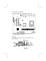
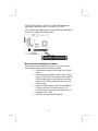
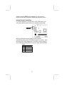
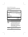
PC CHIPS M701G (V1.1) is a powerful multimedia workstation motherboard that supports Socket-370 Intel Celeron, Pentium III or VIA C3 processors with front-side bus speeds of 133MHz. With the SiS635 chipset and integrated 128-bit 2D/3D Graphics Accelerator, PC CHIPS M701G (V1.1) provides excellent graphics performance for gaming and video applications. The motherboard also has a built-in AC97 Codec, a CNR (Communication Network Riser) slot, and a built-in 10BaseT/100BaseTX Network Interface (optional).
PC CHIPS M701G (V1.1) is a powerful multimedia workstation motherboard that supports Socket-370 Intel Celeron, Pentium III or VIA C3 processors with front-side bus speeds of 133MHz. With the SiS635 chipset and integrated 128-bit 2D/3D Graphics Accelerator, PC CHIPS M701G (V1.1) provides excellent graphics performance for gaming and video applications. The motherboard also has a built-in AC97 Codec, a CNR (Communication Network Riser) slot, and a built-in 10BaseT/100BaseTX Network Interface (optional).


-
 1
1
-
 2
2
-
 3
3
-
 4
4
-
 5
5
-
 6
6
-
 7
7
-
 8
8
-
 9
9
-
 10
10
-
 11
11
-
 12
12
-
 13
13
-
 14
14
-
 15
15
-
 16
16
-
 17
17
-
 18
18
-
 19
19
-
 20
20
-
 21
21
-
 22
22
-
 23
23
-
 24
24
-
 25
25
-
 26
26
-
 27
27
-
 28
28
-
 29
29
-
 30
30
-
 31
31
-
 32
32
-
 33
33
-
 34
34
-
 35
35
-
 36
36
-
 37
37
-
 38
38
-
 39
39


PC CHIPS M701G (V1.1) Specification
- Category
- Motherboards
- Type
- Specification
PC CHIPS M701G (V1.1) is a powerful multimedia workstation motherboard that supports Socket-370 Intel Celeron, Pentium III or VIA C3 processors with front-side bus speeds of 133MHz. With the SiS635 chipset and integrated 128-bit 2D/3D Graphics Accelerator, PC CHIPS M701G (V1.1) provides excellent graphics performance for gaming and video applications. The motherboard also has a built-in AC97 Codec, a CNR (Communication Network Riser) slot, and a built-in 10BaseT/100BaseTX Network Interface (optional).
Ask a question and I''ll find the answer in the document
Finding information in a document is now easier with AI
